
Related Manuals for Crown FM30


Summary of Contents for Crown FM30
- Page 1 FM30/FM150/FM300 Broadcast Transmitter User's Manual ©2007 Crown Broadcast, a division of International Radio and Electronics Corporation 25166 Leer Drive, Elkhart, Indiana, 46514-5425 U.S.A. (574) 262-8900...
-
Page 2: Important Notices
International Radio and Electronics, Inc. Printed in U.S.A. Crown Broadcast attempts to provide information that is accurate, complete, and useful. Should you find inadequacies in the text, please send your comments to the following address: International Radio and Electronics Corporation P.O. -
Page 3: Table Of Contents
Contents Section 1– Getting Acquainted Your Transmitter Applications and Options 1.2.1 Stand Alone 1.2.2 Backup 1.2.3 Booster 1.2.4 Exciter 1.2.5 Translator 1.2.6 Satellator 1.2.7 Nearcasting Transmitter/Exciter Specifications Receiver Specifications Safety Considerations 1-10 1.5.1 Dangers 1-10 1.5.2 Warnings 1-10 1.5.3 Cautions 1-10 Section 2–... - Page 4 RF Exciter Circuit Board Metering Circuit Board Motherboard Display Circuit Board 4-10 Voltage Regulator Circuit Board 4-11 Power Regulator Circuit Board 4-12 4.10 RF Driver/Amplifier (FM30) 4-12 4.11 RF Driver (FM150/FM300) 4-13 4.12 RF Amplifier (FM150/FM300 4-13 4.13 Chassis 4-14 4.14...
- Page 5 Section 5-Adjustments and Tests Audio Processor Adjustments 5.1.1 Pre-Emphasis Selection 5.1.2 Pre-Emphasis Adjustment Stereo Generator Adjustments 5.2.1 Separation 5.2.2 Composite Output Using a Modulation Monitor 5.2.3 19kHz Level 5.2.4 19kHz Phase Frequency Synthesizer Adjustments 5.3.1 Frequency (Channel) Selection 5.3.2 Modulation Compensator 5.3.3 Frequency Measurement and Adjustment 5.3.4 FSK Balance Control Metering Board Adjustments...
- Page 6 Section 6-Reference Drawings Views Board Layouts and Schematics Section 7-Service and Support Service 24-Hour Support Spare Parts Transmitter Output Efficiency Appendix-1 Glossary Index Index-1...
-
Page 7: Section 1-Getting Acquainted
Section 1—Getting Acquainted This section provides a general description of the FM30, FM150, and FM300 transmitters and introduces you to safety conventions used within this document. Review this material before installing or operating the transmitter. Getting Acquainted... -
Page 8: Your Transmitter
This manual describes the FM30, FM150, and FM300 because all three transmitters share common design factors. Specific product differences are noted throughout the manual. In physical appearance, the FM30 differs from the FM150 and FM300 in that it lacks the power amplifier and cooling fan assembly on the back panel. -
Page 9: Applications And Options
1.2 Applications and Options Crown transmitters are designed for versatility in applications. They have been used as stand-alone and backup transmitters and in booster, translator, satellator, and nearcast applications. The following discussion describes these applications further. Model numbers describe the configuration of the product (which has to do with its intended purpose) and the RF output power which you can expect. -
Page 10: Stand Alone
AC power is lost. 1.2.3 Exciter In addition to the standard configuration, the FM30, FM150, and FM300 are available in op- tional configurations to meet a variety of needs. An "E" suffix, as in the FM30E, for example, represents an exciter-only configuration. In this configuration, the audio processor and stereo generator boards are replaced with circuitry to bypass their function. -
Page 11: Translator
1.2.4 Translator A receiver configuration (FM150R, for example) replaces the audio processor/stereo gen- erator board with a receiver module. This added feature makes the FM30, FM150, and FM300 ideal for translator service in terrestrial-fed networks. These networks represent a popular and effective way to increase your broadcasting coverage. Translators, acting as repeater emitters, are necessary links in this chain of events. -
Page 12: Satellator
1.2.6 Nearcasting The output power of an FM30 transmitter can be reduced to a level that could function as a near-cast transmitter. Crown transmitters have been used in this way for language transla- tion, for re-broadcasting the audio of sporting events within a stadium, and for specialized local radio. -
Page 13: Transmitter/Exciter Specifications
1.3 Transmitter/Exciter Specifications Frequency Range 87.9 MHz–107.9 MHz (76 MHz–90 MHz optionally available) RF Power Output (VSWR 1.7:1 or better) FM30 3-33 Watts adjustable FM150 15-165 Watts adjustable FM300 30-330 Watts adjustable RF Output Impedance 50 Ohms Frequency Stability Meets FCC specifications from 0-50... - Page 14 FM30 24-36 volts (36 volts at 3 amps required for full output power) FM150 36-72 volts (48 volts @ 7 amps for full output power) FM300 36-72 volts (72 volts @ 10 amps for full output power) FM30/FM150/FM300 User’s Manual...
- Page 15 Meets FCC, DOC, and CCIR requirements Dimensions 13.5 x 41.9 x 44.5 cm 5.25 x 16.5 x 17.5 inches Weight FM30 10.5 kg (23 lbs) 13.6 kg (30 lbs) shipping weight FM150 11.4 kg (25 lbs) 14.5 kg (32 lbs) shipping weight FM300 16.8 kg (37 lbs)
-
Page 16: Receiver Specifications
1 lb 1.5 Safety Considerations Crown Broadcast assumes the responsibility for providing you with a safe product and safety guidelines during its use. “Safety” means protection to all individuals who install, operate, and service the transmitter as well as protection of the transmitter itself. To promote safety, we use standard hazard alert labeling on the product and in this manual. -
Page 17: Section 2-Installation
Section 2—Installation This section provides important guidelines for installing your transmitter. Review this information carefully for proper installation. Installation... -
Page 18: Operating Environment
2.2 Power Connections The FM30, FM150, and FM300 operate on 100, 120, 220, or 240 volts AC (50 or 60 Hz; sin- gle phase). Each transmitter can operate on DC power as well (28 volts for the FM30, 48 volts for the FM150, and 72 volts for the FM300). - Page 19 Illustration 2–1 Removing the Power Connector Cover Illustration 2–2 Selecting an AC Line Voltage Installation...
-
Page 20: Fuses
Consult the following table: Transmitter Input Power Fuse FM30 100–120 V 220–240 V 1.5 A FM150 100–120 V 6.3 A 220–240 V FM300 100–120 V 12.5 A 220–240 V 6.3 A Illustration 2–4 Fuse Reference Table FM30/FM150/FM300 User’s Manual... -
Page 21: Battery Power
Your transmitter can operate on a DC power source (such as 4 or 5, 12–volt deep cycle bat- teries connected in series). The FM30 requires 28 volts DC for full output power, while the FM150 requires 48 volts, and FM300 requires 72 volts for full output power. Connect the batteries to the red (+) and black (–) battery input binding posts on the rear panel. - Page 22 See illustrations 2-6 and 2-10. Illustration 2–6 Top Cover Removed Megahertz Illustration 2–7 Transmitter Front Panel (Frequency Selector Switches) = 88.10 MHz = 107.90 MHz Illustration 2–8 Two Sample Frequency Selections FM30/FM150/FM300 User’s Manual...
-
Page 23: Modulation Compensator
2.3.1 Modulation Compensator The Modulation trim-potentiometer (see illustration 2–10) compensates for slight variations in deviation sensitivity with frequency. Set the trim-pot dial according to the following graph: Frequency of Operation (MHz) Modulation Compensation Pot Setting 97.1 82.4 Illustration 2–9 Modulation Compensator Settings These compensator settings are approximate. -
Page 24: Receiver Frequency Selection
4. For 75us pre-emphasis short pins 3&4 and 5&6 on J2 of the Receiver card. 5. For 50us pre-emphasis short pins 1&2 and 7&8 on J2 of the Receiver card. 6. After setting the frequency, replace the top cover and screws. FM30/FM150/FM300 User’s Manual... - Page 25 Freq. 74-90 Freq. 88-108 Freq. 74-90 Freq. 88-108 74.9 87.9 78.9 91.9 75.0 88.0 79.0 92.0 75.1 88.1 79.1 92.1 75.2 88.2 79.2 92.2 75.3 88.3 79.3 92.3 75.4 88.4 79.4 92.4 75.5 88.5 79.5 92.5 75.6 88.6 79.6 92.6 75.7 88.7 79.7...
- Page 26 102.5 85.9 98.9 89.6 102.6 86.0 99.0 89.7 102.7 86.1 99.1 89.8 102.8 86.2 99.2 89.9 102.9 86.3 99.3 90.0 103.0 86.4 99.4 103.1 86.5 99.5 103.2 Illustration 2–12-2 Receiver Frequency Selection (Continued on next page) 2-10 FM30/FM150/FM300 User’s Manual...
- Page 27 Freq. 74-90 Freq. 88-108 Freq. 74-90 Freq. 88-108 103.3 107.0 103.4 107.1 103.5 107.2 103.6 107.3 103.7 107.4 103.8 107.5 103.9 107.6 104.0 107.7 104.1 107.8 104.2 107.9 104.3 108.0 104.4 104.5 104.6 104.7 104.8 104.9 105.0 105.1 105.2 105.3 105.4 105.5 105.6...
-
Page 28: Rf Connections
If your transmitter is equipped with the receiver option, connect the incoming RF to the RF IN connector. Illustration 2–13 RF Connections 2-12 FM30/FM150/FM300 User’s Manual... -
Page 29: Audio Input Connections
2.6 Audio Input Connections Attach audio inputs to the Left and Right XLR connectors on the rear panel. (The Left channel audio is used on Mono.) Pin 1 of the XLR connector goes to chassis ground. Pins 2 and 3 represent a balanced differential input with an impedance of about 50 kΩ . They may be connected to balanced or unbalanced left and right program sources. -
Page 30: Sca Input Connections
Input sensitivity is approximately 3.5–volt P-P for 75 kHz deviation. Enable the Composite Input by grounding pin 14 of the Remote I/O connector (see Illustration 2–18). Connect the composite signal using the Composite In BNC connector. 2-14 FM30/FM150/FM300 User’s Manual... -
Page 31: Audio Monitor Connections
Illustration 2–16 Composite In and Audio Monitor Connections 2.9 Audio Monitor Connections Processed, de-emphasized samples of the left and right audio inputs to the stereo genera- tor are available at the Monitor jacks on the rear panel. The signals are suitable for feeding a studio monitor and for doing audio testing. -
Page 32: Program Input Fault Time-Out
Remote control and remote metering of the transmitter is made possible through a 25–pin, D-sub connector on the rear panel. (No connections are required for normal operation.) Illustration 2–17 Remote I/O Connector Illustration 2–18 Remote I/O Connector (DB-25 Female) 2-16 FM30/FM150/FM300 User’s Manual... - Page 33 Pin Number Function Ground FMV Control Composite Out (sample of stereo generator output) FSK In (Normally high; pull low to shift carrier frequency ap- proximately 7.5 KHz. Connect to open collector or relay contacts of user-supplied FSK keyer.) /Auto Carrier Off (Pull low to enable automatic turnoff of carrier with program failure.) Meter Battery (Unregulated DC voltage;...
- Page 34 Notes: 2-18 FM30/FM150/FM300 User’s Manual...
-
Page 35: Section 3-Operation
Section 3—Operation This section provides general operating parameters of your transmitter and a detailed description of its front panel display. Operation... -
Page 36: Initial Power-Up Procedures
These steps summarize the operating procedures you should use for the initial operation of the transmitter. More detailed information follows. 1. Turn on the DC breaker. Illustration 3–1 DC Breaker 2. Turn on the main power switch. Main Power Switch Illustration 3–2 Front Panel Power Switch FM30/FM150/FM300 User’s Manual... - Page 37 C. ALC should be between 4.00 and 6.00 volts. D. PA DC Volts should be 26–30 volts for the FM30, 25–35 volts for the FM150, and 37–52 volts for the FM300. (Varies with antenna match, power, and frequency.) E. PA DC Amperes should be 1.5–2.5 amps for the FM30, 5.5–7.5 amps for the FM150, and 7.0–9.0 amps for the FM300.
-
Page 38: Power Switches
3.2 Power Switches 3.2.1 DC Breaker The DC breaker, on the rear panel, must be on (up) for transmitter operation, even when using AC power. Electrically, the DC breaker is located immediately after diodes which iso- late the DC and AC power supplies. 3.2.2 Power Switch The main on/off power switch controls both the 120/240 VAC and the DC battery power in- put. -
Page 39: Front Panel Bar-Dot Displays
3.3 Front Panel Bar-Dot Displays Bar-dot LEDs show audio input levels, wideband and highband audio gain control, and modulation percentage. Resolution for the gain control and modulation displays is increased over a conventional bar-graph display using dither enhancement which modulates the brightness of the LED to give the effect of a fade from dot to dot. -
Page 40: Input Gain Switches
Processing to “0” or “10”. 3.6 Stereo-Mono Switch The Stereo-Mono slide switch selects the transmission mode. In Mono, feed audio only to the left channel. Although right-channel audio will not be heard as audio modulation, it will affect the audio processing. FM30/FM150/FM300 User’s Manual... -
Page 41: Rf Output Control
3.7 RF Output Control Set this control for the desired output power level. Preferably, set the power with an external RF wattmeter connected in the coaxial line to the antenna. You may also use the RF power reading on the digital multimeter. The control sets the RF output voltage. -
Page 42: Fault Indicators
(176° F) for the FM150 and FM300. At about 55° C (131°F) for the FM30 or 82°C (180° F) for the FM150 and FM300, ALC volt- age begins to decrease, reducing the PA supply voltage to prevent a further increase in temperature. -
Page 43: Section 4-Principals Of Operation
Section 4—Principles of Operation This section discusses the circuit principles upon which the transmitter functions. This information is not needed for day-to-day operation of the transmitter but may be useful for advanced users and service person- nel. Principles of Operation... -
Page 44: Part Numbering
4.1 Part Numbering As this section refers to individual components, you should be familiar with the part number- ing scheme used. The circuit boards and component placement drawings use designators such as “R1”, “R2”, and “C1.” These same designators are used throughout the transmitter on several different circuit boards and component placement drawings. -
Page 45: Stereo Generator Circuit
4.2 Audio Processor/Stereo Generator Circuit Board The audio board provides the control functions of audio processing-compression, limiting, and expansion, as well as stereo phase-error detection, pre-emphasis and generation of the composite stereo signal. Illustration 6-4 and accompanying schematic may be useful to you during this discussion. The overall schematic for the audio board is divided into two sheets;... -
Page 46: Stereo Generator Section
6.2 4.2.2 Stereo Generator Section Composite stereo signal is generated from left and right-channel audio inputs. This section also has the amplifier (U201) for an optional external composite input and provision for in- sertion of SCA signal(s). FM30/FM150/FM300 User’s Manual... - Page 47 Processed, pre-emphasized left and right audio is passed through third-order lowpass filters comprised of U202A (203A) and associated circuitry. The filters decrease the level of audio products below 30 Hz. This low-frequency roll off is necessary to prevent disturbance to the phase-lock loop in the RF frequency synthesizer by extremely low-frequency audio compo- nents.
-
Page 48: Rf Exciter Circuit
U14A., allowing for greater loop band- width with less degradation of the low frequency audio response. Lock and unlock status signals are available at the outputs of U15E and U15F respectively. Modulation is introduced to the VCO though R72 and R122. FM30/FM150/FM300 User’s Manual... -
Page 49: Metering Circuit Board
4.5 Metering Circuit The ALC and metering circuitry is on the motherboard (see Illustration 6–6). This circuit processes information for the RF and DC metering, and produces ALC (RF level-control) bias. It also provides reference and input voltages for the digital panel meter, voltages for remote metering, fan control, and drive for the front-panel fault indicators. -
Page 50: Motherboard
The motherboard has configuration jumpers associated with different options that can be added at the time of order or at a later time as an upgrade. The motherboard configuration chart for these jumpers can be found on the following page. Configuration Jumpers Illustration 4–4 Configuration Jumpers FM30/FM150/FM300 User’s Manual... - Page 51 Motherboard Jumper Configuration Chart 4.6.1 Jumper FMA “E” FMA“T” FMA“T” FMA “R” 50KΩ input 600Ω input “Omnia” “Omnia” Analog AES input input Short Short Short Short Short Open Short Short Short Short Short Open Open Open Short Open Open Open Open Open Open...
-
Page 52: Display Circuit Board
Processing control, R50, is part of the audio processor. (See section 4.2.) The DPM IN and DPM REF lines are analog and reference voltage inputs to digital multime- ter IC U12. They originate from analog data selectors on the ALC/ metering board. 4-10 FM30/FM150/FM300 User’s Manual... -
Page 53: Voltage Regulator Circuit Board
4.8 Voltage Regulator Circuit Board The voltage regulator board is the longer of two boards mounted under the chassis toward the front of the unit. It has switch-mode voltage regulators to provide +12, –12, and 20 volts. It also contains the program detection and automatic carrier control circuits. Illustration 6–10 and accompanying schematic complement this discussion. -
Page 54: Power Regulator Circuit Board
BLF246 MOSFET amplifier. The BLF245 stage operates from a supply voltage of 28 volts in the FM30. The circuit board has components for input and output coupling and for power supply filter- ing. -
Page 55: Rf Driver (Fm150/Fm300)
4.11 RF Driver (FM150/FM300) The RF Driver assembly is mounted on a 100 mm x 100 mm plate in the under side of the chassis. Illustration 6-14 and accompanying schematic complement this discussion. The driver amplifies the approximate 20 milliwatts from the frequency synthesizer to about 8 watts to drive the RF power amplifier. -
Page 56: Chassis
The main energy-storage/filter capacitor, C01, is located between the voltage and power regulator boards. The DC voltage across the capacitor will be 45–55 volts (FM30 and FM150) or 65–70 volts (FM300) when the carrier is on. 4.14 RF Output Filter & Reflectometer The RF low-pass filter/reflectometer are located in the right-hand compartment on the top of the chassis. -
Page 57: Receiver Circuit Board Option
4.15 Receiver Circuit Board Option This option allows the transmitter to be used as a translator. The receiver board receives terrestrially fed RF signal and converts it to composite audio which is then fed into the ex- citer board. Microprocessor controlled phase lock loop technology ensures the received fre- quency will not drift, and multiple IF stages ensure high adjacent channel rejection. - Page 58 12 volts from the motherboard is filtered and supplies various needs on the board. Finally there is a precision reference voltage. Two 2.5 volt reference shunts act very much like a very accurate zener diode to provide a precision 5 volt supply to the metering board. 4-16 FM30/FM150/FM300 User’s Manual...
-
Page 59: Section 5-Adjustments And Tests
Section 5—Adjustments and Tests This section describes procedures for (1) advanced users who may be interested in customizing or optimizing the performance of the transmit- ter and (2) service personnel who want to return the transmitter to op- erational status following a maintenance procedure. Adjustments and Tests... -
Page 60: Audio Processor Adjustments
TP301 on the RF Exciter circuit board. Ad- just the Separation control R244 for a straight centerline. Since proper adjustment of this control coincides with best stereo separation, use an FM monitor to make or confirm the adjustment. FM30/FM150/FM300 User’s Manual... -
Page 61: Composite Output
5.2.2 Composite Output You can make adjustments to the composite output in the following manner: Using a Modulation Monitor 1. Set the Stereo-Mono switch to Mono. 2. Check that the setting of the Modulation compensation control (see illustration 2–9) on the RF Exciter circuit , falls within the range specified for the frequency of operation. -
Page 62: Modulation Compensator
With the front panel RF Output control fully clockwise, adjust the Power Set trim pot (R55) to 10% more than the rated power (33 W for FM30, 165 W for FM150, 330 W for FM300) as indicated on an accurate external watt meter. If the authorized power is less than the maxi- mum watts, you may use the Power Set to limit the range of the RF Output control. -
Page 63: Swr Calibrate
5.4.3 SWR Calibrate When the Carrier switch is off, or the RF power is less than about 5 watts, the SWR circuit automatically switches to a calibrate-check mode. (See section 4.5 for more information.) Set the digital panel meter to read SWR. With the Carrier switch off, set the SWR CAL trim pot (R66) to read 1.03. -
Page 64: Voltage Regulator Adjustment
You may select other times by changing the value of R21. The time is proportional to the re- sistance. 5.8 Bias Set (RF Power Amplifier) The Bias Set trim pot is located inside the PA module on the input circuit board. Set the trim pot to its midpoint for near-optimum bias. FM30/FM150/FM300 User’s Manual... -
Page 65: Performance Verification
5.9 Performance Verification Measure the following parameters to receive a comprehensive characterization of trans- mitter performance: • Carrier frequency • RF output power • RF bandwidth and RF harmonics (see section 5.12) • Pilot frequency, phase, and modulation percentage • Audio frequency response •... -
Page 66: Carrier Frequency
For the response tests, take the readings from an FM modulation monitor. Make audio frequency response measurements for left and right channels at frequencies of 50 Hz, 100 Hz, 400 Hz, 1 kHz, 5 kHz, 10 kHz, and 15 kHz. See sections 5.9.1 and 5.9.2. FM30/FM150/FM300 User’s Manual... -
Page 67: Audio Distortion
5.15 Audio Distortion Make distortion measurements from the de-emphasized output of an FM modulation moni- tor. Make audio distortion measurements for left and right channels at frequencies of 50 Hz, 100 Hz, 400 Hz, 1 kHz, 5 kHz, 10 kHz, and 15 kHz. See sections 5.9.1 and 5.9.2. 5.16 Modulation Percentage While feeding an audio signal into the left channel only, confirm that the total modulation percentage remains constant when switching between Mono and Stereo. -
Page 68: 38Khz Subcarrier Suppression
10. Test ALC action with PA current overload, SWR, and PLL lock. NOTE: FCC type acceptance procedures call for testing the carrier frequency over the temperature range of 0–50 degrees centigrade, and at line voltages from 85% to 115% of rating. (See FCC Part 2.1055.) 5-10 FM30/FM150/FM300 User’s Manual... - Page 69 Section 6—Reference Drawings The illustrations in this section may be useful for making adjustments, taking measurements, troubleshooting, or understanding the circuitry of your transmitter. Reference Drawings...
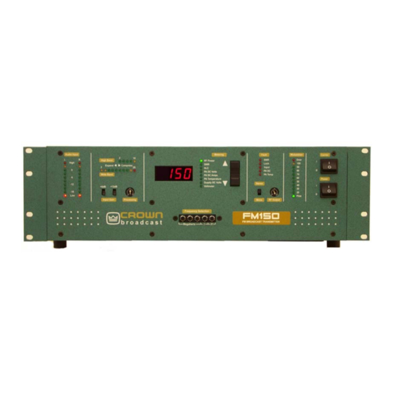
- Page 70 Illustration 6-1 Front View RF Output Receiver Input Composite Input Audio Inputs (Optional) RF Output Monitor Audio Monitors SCA Inputs Remote I/O AC Power Input RF Power Amplifier DC Input (FM150/300 Only) Circuit Breaker Illustration 6-2 Rear View FM30/FM150/FM300 User’s Manual...
- Page 71 Metering Circuit Audio Processor Section RF Low Pass Filter & Reflectometer Stereo Generator Section RF Exciter Circuit DC Input RF output Power Amplifier (FM150/M300 Only) Illustration 6-3 Chassis Top View Voltage Regulator Power Regulator RF Pre-driver/ Amplifier Filter Capacitor AC Power Transformer Bridge Rectifier AC Power...
- Page 72 Notes: FM30/FM150/FM300 User’s Manual...
- Page 73 6.2 Board Layout and Schematics Illustration 6-5 Audio Processor/Stereo Generator Board FM30/FM150/FM300 User’s Manual...
- Page 74 THE BASIS FOR THE MANUFACTURE OR SALE OF APPARATUS OR INCLUDING ASSOCIATED ELECTRONIC REPRODUCTIONS DEVICES WITHOUT PERMISSION. ARE FOR REFERENCE ONLY. FILENAME: SCALE : NONE PROJ NO. SHEET Schematic Diagram: Audio Processor/ Stereo Generator (Sheet 1 of 2) Adjustments and Tests FM30/150/300 User’s Manual...
- Page 75 THE BASIS FOR THE MANUFACTURE OR SALE OF APPARATUS OR INCLUDING ASSOCIATED ELECTRONIC REPRODUCTIONS DEVICES WITHOUT PERMISSION. ARE FOR REFERENCE ONLY. SCALE : NONE PROJ NO. SHEET Schematic Diagram: Audio Processor/ Stereo Generator (Sheet 2 of 2) FM30/FM150/FM300 User’s Manual...
- Page 76 Board Layouts and Schematics Illustration 6-6 Motherboard Adjustments and Tests FM30/150/300 User’s Manual...
- Page 77 THE BASIS FOR THE MANUFACTURE OR SALE OF APPARATUS OR HEADER 5 x 2 XLR CON. ARE FOR REFERENCE ONLY. DEVICES WITHOUT PERMISSION. FILENAME: SCALE : NONE PROJ NO. SHEET Schematic Diagram: Motherboard (Sheet 1 of 3) FM30/FM150/FM300 User’s Manual...
- Page 78 2N5210 5.11K SWR CAL 51.1K R199 R172 R201 74HC132 TL074 74HC132 100K 1N4148 R202 R180 100K 20pF U23C 1N4148 OPEN FOR FM30 UNITS .01uF 4.7uF (.135V) U10B TANT. TL074 TL072 1.15K 100K C135 R211 .001 49.9K 100K 74HC132 LM394 1N4148...
- Page 79 BAND LIMIT OFFSET DIRECT FSK FREQ. ADJ. AUTO ID RF_LVL TITLE: SCH, UNIVERSAL MOTHER BOARD SIZE DWG . NO . 201497F-SCH SCALE : NONE PROJ NO. SHEET C_L_SHT2_A.DOT REV. A Schematic Diagram: Motherboard (Sheet 3 of 3) FM30/FM150/FM300 User’s Manual 6-11...
- Page 80 SHALL NOT BE REPRODUCED, COPIED OR USED AS THE BASIS FOR THE MANUFACTURE OR SALE OF APPARATUS OR DEVICES WITHOUT PERMISSION. FILENAME: SCALE : NONE PROJ NO. SHEET A_P_SHT1_A.DOT REV. A Schematic Diagram: FM Frequency Selection 6-12 Adjustments and Tests FM30/150/300 User’s Manual...
- Page 81 Illustration 6-9 FM Display Board FM30/FM150/FM300 User’s Manual 6-13...
- Page 82 THE BASIS FOR THE MANUFACTURE OR SALE OF APPARATUS OR INCLUDING ASSOCIATED ELECTRONIC REPRODUCTIONS 2. ALL CAPACITORS ARE IN MICROFARADS. DEVICES WITHOUT PERMISSION. ARE FOR REFERENCE ONLY. FILENAME: SCALE : NONE PROJ NO. SHEET C_L_SHT1_A.DOT REV. A Schematic Diagram: FM Display 6-14 Adjustments and Tests FM30/150/300 User’s Manual...
- Page 83 Illustration 6-10 FM Voltage Regulator FM30/FM150/FM300 User’s Manual 6-15...
- Page 84 1. ALL RESISTORS ARE IN OHMS, 1/4W, 5% TOL. 2. ALL CAPACITORS ARE IN MICROFARADS. 10.0K 3. FOR FM30, 100 & 250 UNITS, R32 VALUE = 82.5K OHM, 1/4W, 1% TOL.. FOR HARRIS UNITS, R32 VALUE = 100K OHM, 1/4W, 1% TOL. 100.0 +UNREG 10.0K...
- Page 85 Illustration 6-11 FM Power Regulator FM30/FM150/FM300 User’s Manual 6-17...
- Page 86 FOR THE MANUFACTURE OR SALE OF APPARATUS OR ARE FOR REFERENCE ONLY. DEVICES WITHOUT PERMISSION. FILENAME: 200915-SCH PROJ NO. SHEET C10582-2 C10582-2 C10582-2 C10582-2 SCALE : NONE B_L_SHT1_A.DOT REV. A Schematic Diagram: FM Power Regulator 6-18 Adjustments and Tests FM30/150/300 User’s Manual...
- Page 87 Illustration 6-12 FM Power Amplifier FM150/FM300 FM30/FM150/FM300 User’s Manual 6-19...
- Page 88 INCLUDING ASSOCIATED ELECTRONIC REPRODUCTIONS FOR THE MANUFACTURE OR SALE OF APPARATUS OR ARE FOR REFERENCE ONLY. DEVICES WITHOUT PERMISSION. FILENAME: PROJ NO. SHEET SCALE : NONE B_L_SHT1_A.DOT REV. A Schematic Diagram: FM RF Amplifier 6-20 Adjustments and Tests FM30/150/300 User’s Manual...
- Page 89 Illustration 6-13 FM Low Pass Filter #2 FM30/FM150/FM300 User’s Manual 6-21...
- Page 90 INCLUDING ASSOCIATED ELECTRONIC REPRODUCTIONS FOR THE MANUFACTURE OR SALE OF APPARATUS OR ARE FOR REFERENCE ONLY. DEVICES WITHOUT PERMISSION. FILENAME: PROJ NO. SHEET SCALE : NONE B_L_SHT1_A.DOT REV. A Schematic Diagram: FM Low Pass Filter #2 Adjustments and Tests 6-22 FM30/150/300 User’s Manual...
- Page 91 Illustration 6-14 FM RF Driver FM30/FM150/FM300 User’s Manual 6-23...
- Page 92 OPEN OPEN OPEN OPEN 33uH FOR FM30: Vout 20VDC INPUT APPLIED HERE. FOR FM100 AND FM250: 18V OPEN FOR FM500: 20V FOR FM30: FEED POINT FROM PWR. REGULATOR PWB. OPEN +24VDC OPEN 4.7K OPEN 1/2W 2.7K NTC 1N753A 0.01 OPEN OPEN 6.2V...
- Page 93 AND SHALL NOT BE REPRODUCED, COPIED OR USED AS THE BASIS 200419-SCH FOR THE MANUFACTURE OR SALE OF APPARATUS OR DEVICES WITHOUT PERMISSION. FILENAME: SHEET 200419-SCH-2.SCH PROJ NO. SCALE : NONE A_L_SHT1_A.DOT REV. A Schematic Diagram: FM Euroamp DC Input Feedthru FM30/FM150/FM300 User’s Manual 6-25...
- Page 94 THE BASIS FOR THE MANUFACTURE OR SALE OF APPARATUS OR INCLUDING ASSOCIATED ELECTRONIC REPRODUCTIONS DEVICES WITHOUT PERMISSION. ARE FOR REFERENCE ONLY. FILENAME: SCALE : NONE PROJ NO. SHEET C_L_SHT1_A.DOT REV. A Schematic Diagram: FM Chassis Interconnect 6-26 Adjustments and Tests FM30/150/300 User’s Manual...
- Page 95 Section 7—Service and Support We understand that you may need various levels of support or that the product could require servicing at some point in time. This section pro- vides information for both of these scenarios. Service and Support...
-
Page 96: Spare Parts
You may be required to leave a message at this number but your call will be returned promptly from our on-call technician. 7.3 Spare Parts To obtain spare parts, call Crown Broadcast Sales at the following number. (866) 262-8919 You may also write to the following address: International Radio and Electronics Corporation P.O. - Page 97 Procedure for Obtaining Warranty Service Crown Broadcast will repair or service, at our discretion, any product failure as a result of normal in- tended use. Warranty repair can only be performed at our plant facility in Elkhart, Indiana USA or at a factory authorized service depot.
- Page 98 Switching Regulator, 0.75A LM3578AN 2 NTC, In-rush Current Limiter EMI Filter, 6A 250V with Fuse 14 Stage Bin Cntr/OSC 74HC4060 These parts are included in the FM30 kit (part number GFM30SPARES): Item Quantity Fuse, 1.5A Slo-blo 5mmX20mm Fuse, 3A Slo-blo 5mmX20mm...
-
Page 99: Factory Service Instructions
We do not cover any charges for shipping outside the U.S. or any of the expenses involved in clearing customs. If you have any questions about your Crown Broadcast product, please contact Crown Broadcast Customer Service at: Telephone: (866) 262-8917 or (866) 262-8919... -
Page 100: Transmitter Output Efficiency
Power measurements were made at 97.1 MHz. Voltage and current measurements were taken from the unit’s built-in metering. The accuracy of the internal metering is better than 2%. Return loss of the RF load was greater than –34 dB at test frequency . FM30/FM150/FM300 User’s Manual... - Page 101 Transmitter Output Efficiency RF Power Output-FM 150 PADC Volts PADC Amps RF Power Efficiency 34.3 6.05 79.5 32.8 5.87 77.9 28.4 5.34 74.5 23.1 4.77 68.1 16.4 4.09 56.7 3.16 50.5 Power measurements were made at 97.9 MHz. Voltage and current measurements were taken from the unit’s built-in metering.
- Page 102 Notes: FM30/FM150/FM300 User’s Manual...
- Page 103 Glossary The following pages define terms and abbreviations used throughout this manual. Glossary...
- Page 104 Digital Panel Meter EPROM Erasable Programmable Read Only Memory Exciter (1) A circuit that supplies the initial oscillator used in the driver stage. (2) A transmitter configuration which excludes stereo generation and audio processing. FM30/FM150/FM300 User’s Manual...
- Page 105 Field-Effect Transistor Frequency Synthesizer A circuit that generates precise frequency signals by means of a single crystal oscillator in conjunction with frequency dividers and multipliers. Frequency Modulation; the process of impressing a radio signal by varying its frequency. Frequency Shift Keying; an F technique for shifting the frequency of the main carrier at a Morse code rate.
- Page 106 Used in conjunction with terrestrial networks. Satellator A transmitter equipped with an FSK ID option for re-broadcasting a satellite fed signal. VSWR Voltage Standing Wave Ratio; see “SWR.” Wideband See “Broadband.” Voltage Controlled Oscillator FM30/FM150/FM300 User’s Manual...
- Page 107 Index Symbols 19–kHz Cables level adjustment 5–3 audio input 2–13 phase adjustment 5–3 Carrier 4–12,5–8 automatic turnoff 2–16,3–8,5–6,5–10 frequency 5–8, 5-10 Carrier switch 3–4,5–5 AC. See Power: input Channel. See Frequency ALC 3–3,3–7,4–7 main 5–10 Altitude main into sub 5–10 operating range 1–8 sub into main 5–10 Amperes PA DC 3–3,3–8...
- Page 108 5-4 display modulation calibration 5-5 location 4-7 FSK 1-5, 1-6 Modulation 2-12, 3-5, 5-3, 5-7, 5-8 measurements 5-4 calibration 5-5 Fuses 2-4, 7-4 compensator 2-7 display 3-5 percentage 3-5, 5-9 Gain control 3-5 Monitor audio 2-15, 4-5 FM30/FM150/FM300 User’s Manual...
- Page 109 Processing M (continued) audio 1-2, 3-5 Mono control 3-6 operation 2-13, 3-6 control setting 3-3 Motherboard highband 3-5, 4-4 circuit description 4-8 Program failure 2-16, 5-10 Multimeter 3-7 Program source 2-13, 3-6 front panel 3-3 Receiver Nearcast frequency selection 2-8 transmitter use 1-6 option 1-5 Networks...
- Page 110 5-7, 5-10 Time-out program input failure 2-16 Transformer 4-14 Translator transmitter use 1-5 VCO 4-6 Voltage AC selection 2-2 Voltage regulator 3-8 adjustments 5-6 circuit description 4-11 Voltage selection 2-2 Voltmeter display 3-8 Volts PA DC 3-3, 3-8 FM30/FM150/FM300 User’s Manual...