
Related Manuals for Crown FM5


Summary of Contents for Crown FM5
- Page 1 FM5 Transmitter User's Manual ©2020 Crown Broadcast, a division of International Radio & Electronics Corporation 2524 Toledo Road, Elkhart, Indiana, 46516, U.S.A. (574) 262-8900...
- Page 2 International Radio & Electronics Corporation. Printed in U.S.A. Crown Broadcast attempts to provide information that is accurate, complete, and useful. Should you find inadequacies in the text, please send your comments to the following address: International Radio &...
-
Page 3: Table Of Contents
Contents Section 1– Getting Acquainted Your Transmitter Applications and Options 1.2.1 Stand Alone 1.2.2 FM5, SDoC approved Transmitter/Exciter Specifications Safety Considerations 1.5.1 Dangers 1.5.2 Warnings 1.5.3 Cautions Section 2– Installation Operating Environment Power Connections - AC & Fuse Frequency (Channel) Selection 2.3.1 Modulation Compensator... - Page 4 FM5 User’s Manual...
-
Page 5: Section 1-Getting Acquainted
Section 1—Getting Acquainted This section provides a general description of the FM5 transmitter and introduces you to safety conventions used within this document. Review this material before installing or operating the transmitter. Getting Acquainted... -
Page 6: Your Transmitter
1.1 Your Transmitter The FM5 is a member of a family of FM stereo broadcast transmitters. Crown transmitters are known for their integration, ease-of-use, and reliability. The integration is most apparent in the standard transmitter configuration which incorporates stereo generation and RF amplification without compromised signal quality. -
Page 7: Applications And Options
1.2 Applications and Options Crown transmitters are designed for versatility in applications. The FM5 can be used as a stand-alone transmitter and in nearcast applications. The following discussion describes these applications further. Model numbers describe the configuration of the product (which has to do with its intended purpose) and the RF output power which you can expect. -
Page 8: Stand Alone
1.2.1 Stand-Alone In the standard configuration, the FM5 is an ideal stand-alone transmitter. When you add an audio source (monaural, L/R stereo, or composite signal), an antenna, and AC power, the transmitter becomes a complete FM stereo broadcast station, capable of serving your small venue requirements, whether inside a church, outside in a parking lot, football stadium, race track or drive-in-theater. -
Page 9: Transmitter/Exciter Specifications
1.3 Transmitter/Exciter Specifications 87.9 MHz–107.9 MHz Frequency Range (VSWR 1.7:1 or better) RF Power Output 0-5.5 Watts adjustable 50 Ohms RF Output Impedance Meets FCC specifications from 0-50 Frequency Stability degrees C 50k Ω bridging, balanced, or 600 Ω Audio Input Impedance Selectable for –10 dBm to +10 dBm for Audio Input Level 75 kHz deviation at 400 Hz... - Page 10 10–15% lower than stated. Regulatory Type notified FCC SDoC Meets FCC, DOC, and CCIR requirements 27.94 x 41.91 x 2.54 cm Dimensions 11 x 16.5 x 1 inches Weight 2.7 kg (6 lbs) 3.6 kg (8 lbs) shipping weight FM5 User’s Manual...
-
Page 11: Safety Considerations
1.4 Safety Considerations Crown Broadcast assumes the responsibility for providing you with a safe product and safety guidelines during its use. “Safety” means protection to all individuals who install, operate, and service the transmitter as well as protection of the transmitter itself. To promote safety, we use standard hazard alert labeling on the product and in this manual. - Page 12 FM5 User’s Manual...
-
Page 13: Section 2-Installation
Installation Installation Section 2—Installation This section provides important guidelines for installing your transmitter. Review this information carefully for proper installation. Installation... -
Page 14: Operating Environment
2.2 Power Connections - AC & Fuse The FM5 operates on 120 volts AC (50 or 60 Hz; single phase). The fuse holder is located on the back panel to the left of the On/Off switch. -
Page 15: Frequency (Channel) Selection
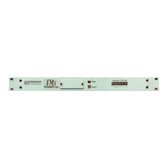
2.3 Frequency (Channel) Selection Your transmitter is capable of operating between 87.9 and 107.9 MHz in the FM band. To adjust the operating frequency, follow these 0.1 MHz steps: 1. Locate the frequency selector switch on the front panel which will be used to change the setting. - Page 16 However, if another antenna is attached, you will need to remove the top cover and clip or unsolder the wire from the resistor to the BNC. See illustration 2-10 below. RF Output Illustration 2–9 RF Output Cut or Unsolder before attaching a different antenna Illustration 2–10 FM5 User’s Manual...
-
Page 17: Audio Input Connections
2.5 Audio Input Connections Attach audio inputs to the Left and Right XLR connectors on the rear panel. (The Left channel audio is used on Mono.) Pin 1 of the XLR connector goes to chassis ground. Pins 2 and 3 represent a balanced differential input with an impedance of about 50 kΩ . They may be connected to balanced or unbalanced left and right program sources. -
Page 18: Composite Input Connection
You may feed composite stereo (or mono audio) directly to the RF exciter bypassing the internal audio processor and stereo generator. To use the Crown transmitter with composite input, it is necessary to use the Composite Input section of the transmitter. This will feed composite stereo (or mono audio) directly to the RF exciter and will bypass the internal ste- reo generator. -
Page 19: Audio Monitor Connections
Illustration 2–14 Audio Monitor Connections 2.9 Pre-emphasis Selection FM5 is set-up for 75 µsec. If you wish to change it to be 50 µsec or flat, please call the Crown Service department and they will walk you through the steps. - Page 20 FM5 User’s Manual...
-
Page 21: Section 3-Operation
Section 3—Operation This section provides general operating parameters of your transmitter and a detailed description of the front panel display. Operation... -
Page 22: Power Switch
These steps summarize the operating procedures you should use for the initial operation of the transmitter. More detailed information follows. 1. Plug in the power cord at the back of the unit. Turn on the power switch. Power Switch Illustration 3–1 Rear Panel Power Switch FM5 User’s Manual... -
Page 23: Peak Modulation
3.2 Peak Modulation This part of the circuitry is not yet available. 3.3 Stereo-Mono Switch The Stereo-Mono blue push button switch is located inside the front panel opening. This switch selects the transmission mode. In Mono, feed audio only to the left channel. Although right-channel audio will not be heard as audio modulation, it will affect the audio processing. -
Page 24: Rf Output Control
Whether you are using a STA or Part 15, you must stay within your broadcast permission area or the FCC may access heavy fines. Illustration 3–3 XLR RF Output Control FM5 User’s Manual... - Page 25 Section 4—Service and Support We understand that you may need various levels of support or that the product could require servicing at some point in time. This section pro- vides information for both of these scenarios. Service and Support...
- Page 26 Our Customer Service Representative will give you further instructions regarding the return of your product. Use the original shipping carton or a new one obtained from Crown. You may be required to leave a message at this number but your call will be returned promptly from our on-call technician.
-
Page 27: Service & Support
Procedure for Obtaining Warranty Service Crown Broadcast will repair or service, at our discretion, any product failure as a result of normal in- tended use. Warranty repair can only be performed at our plant facility in Elkhart, Indiana USA or at a factory authorized service depot. - Page 28 FM5 User’s Manual...
-
Page 29: Glossary
Glossary Audio Frequency; the frequencies between 20 Hz and 20 kHz in the electromagnetic spectrum. Amplitude Modulation; the process of impressing information on a radio-frequency signal by varying its amplitude. The range of frequencies available for signaling. Bandwidth A bayonet locking connector for miniature coax; said to be short for Bayonet-Neill-Concelman. - Page 30 A carrier signal which operates at a lower frequency Subcarrier than the main carrier frequency and which modulates the main carrier. The process used to hold back or stop certain Suppression frequencies. Total Harmonic Distortion Voltage Standing Wave Ratio; see “SWR.” VSWR See “Broadband.” Wideband FM5 User’s Manual...
- Page 31 Frequency of Operation (MHz) Modulation Compensation Pot Setting 97.1 82.4 Illustration A-1 Modulation Compensator Settings These compensator settings are approximate. Each mark on the potentiometer represents about 10% modulation compensation. Modulation Compensator Pot Illustration A-2 Modulation Compensator Pot Appendix A FM5 User’s Manual...