
Related Manuals for Crown FM30


Summary of Contents for Crown FM30
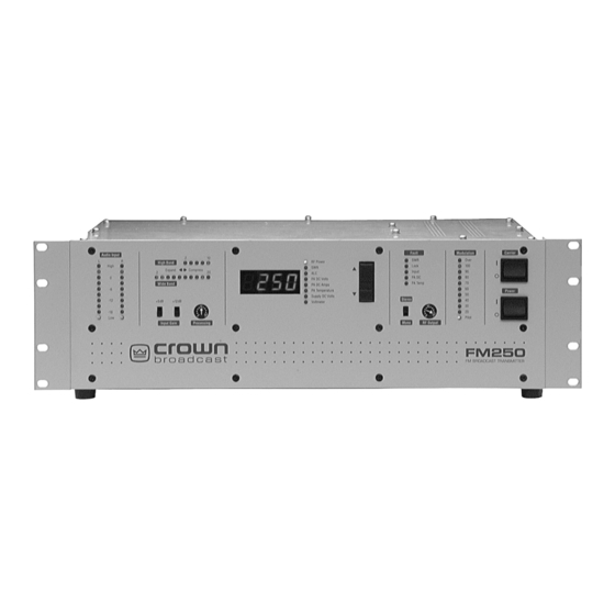
- Page 1 ® FM30/FM100/FM250 Broadcast Transmitter User's Manual ©2005 Crown Broadcast, a division of International Radio and Electronics, Inc. 25166 Leer Drive, Elkhart, Indiana, 46514-5425 U.S.A. (574) 262-8900...
-
Page 2: Important Notices
April 2005 Important Notices ©2005, Crown Broadcast, a division of International Radio and Electronics, Inc. Portions of this document were originally copyrighted by Michael P. Axman in 1991. All rights reserved. No part of this publication may be reproduced, transmitted, transcribed, stored in a retrieval system, or translated into any language in any form by any means without the written permission of Crown International, Inc. -
Page 3: Table Of Contents
Contents Contents Contents Contents Contents Section 1—Getting Acquainted ........1–1 1.1 Your Transmitter ....................1–2 1.2 Applications and Options ................... 1–3 1.2.1 Stand-Alone ....................1–4 1.2.2 Backup ......................1–4 1.2.3 Booster ......................1–4 1.2.4 Exciter ......................1–4 1.2.5 Translator ...................... 1–5 1.2.6 Satellator ...................... - Page 4 4.7 Display Circuit Board ..................4–10 4.8 Voltage Regulator Circuit Board ..............4–11 4.9 Power Regulator Circuit Board ................ 4–12 4.10 RF Driver/Amplifier (FM30) ................4–12 4.11 RF Driver (FM100/FM250) ................4–13 4.12 RF Amplifier (FM100/FM250) ................4–13 4.13 Chassis ......................4–14 4.14 RF Output Filter &...
- Page 5 Section 5—Adjustments and Tests ......... 5–1 5.1 Audio Processor Adjustments ................5–2 5.1.1 Pre-Emphasis Selection ................5–2 5.1.2 Pre-Emphasis Fine Adjustment ..............5–2 5.2 Stereo Generator Adjustments ................5–2 5.2.1 Separation ....................5–2 5.2.2 Composite Output ..................5–2 Using a Modulation Monitor 5–3 5.2.3 19–kHz Level ....................
- Page 6 Section 6—Reference Drawings ........6–1 6.1 Views ........................ 6–2 6.2 Board Layouts and Schematics ................. 6–4 Section 7—Service and Support ........7–1 7.1 Service ......................7–2 7.2 24–Hour Support ....................7–2 7.3 Spare Parts ....................... 7–2 Transmitter Output Efficiency ......Appendix–1 Glossary ..............
-
Page 7: Section 1-Getting Acquainted
I NFORMATION Section 1—Getting Acquainted This section provides a general description of the FM30, FM100, and FM250 transmitters and introduces you to safety conventions used within this document. Review this material before installing or operating the transmitter. Getting Acquainted 1–1... -
Page 8: Your Transmitter
Your Transmitter The FM30, FM100, and FM250 are members of a family of FM stereo broadcast transmitters. Crown transmitters are known for their integration, ease-of-use, and reliability. The integration is most apparent in the standard transmitter configuration which incorporates audio processing, stereo generation, and RF amplification without compromised signal quality. -
Page 9: Applications And Options
Applications and Options Crown transmitters are designed for versatility in applications. They have been used as stand-alone and backup transmitters and in booster, translator, satellator, and nearcast applications. The following discussion describes these applications further. Model numbers describe the configuration of the product (which has to do with its intended purpose) and the RF output power which you can expect. -
Page 10: Stand-Alone
Transfer switches on each side of the existing and backup transmitters make the change-over possible with minimal downtime. The DC operation option of the FM30, FM100, and FM250 make them attractive backup units for those times when AC power is lost. -
Page 11: Translator
A receiver configuration (FM100R, for example) replaces the audio processor and stereo generator boards with a receiver module. This added feature makes the FM30, FM100, and FM250 ideal for translator service in terrestrial-fed networks. These networks represent a popular and effective way to increase your broadcasting coverage. -
Page 12: Satellator
1.2.7 Nearcasting The output power of an FM30 transmitter Can be reduced to a level that could Function as a near-cast transmitter. Crown transmitters have been used in this way for language translation, for rebroadcasting the audio of sporting events within a stadium, and for specialized local radio. -
Page 13: Transmitter/Exciter Specifications
Transmitter/Exciter Specifications Frequency Range 87.9 MHz–108 MHz (76 MHz–90 MHz optionally available) RF Power Output (VSWR 1.5:1 or better) FM30 3 - 30 watts, adjustable FM100 10 - 100 watts, adjustable FM250 20 - 250 watts, adjustable RF Output Impedance... - Page 14 FM30 24–36 volts (36 volts at 3 amps required for full output power) FM100 and FM250 36–62 volts [48 volts at 5 amps (FM100) or 72 volts at 8 amps (FM250) required for full output power] 1–8 FM30/FM100/FM250 User's Manual...
- Page 15 Meets FCC, DOC, and CCIR requirements Dimensions 13.5 x 41.9 x 44.5 cm (5.25 x 16.5 x 17.5 inches) Weight FM30 10.5 kg (23 lbs) 13.6 kg (30 lbs) shipping weight FM100 11.4 kg (25 lbs) 14.5 kg (32 lbs) shipping weight FM250 16.8 kg (37 lbs)
-
Page 16: Receiver Specifications
1 lb Safety Considerations Crown Broadcast assumes the responsibility for providing you a safe product and safety guidelines during its use. “Safety” means protection to all individuals who install, operate, and service the transmitter as well as protection of the transmitter itself. -
Page 17: Section 2-Installation
Section 2—Installation This section provides important guidelines for installing your trans- mitter. Review this information carefully for proper installation. Installation 2–1... -
Page 18: Operating Environment
Power Connections The FM30, FM100, and FM250 operate on 100, 120, 220, or 240 volts AC (50 or 60 Hz; single phase). Each transmitter can operate on DC power as well (28 volts for the FM30, 36 volts for the FM100, and 62 volts for the FM250). The transmitter can operate on fewer volts DC, but with reduced RF output power (see section 1.2). - Page 19 120Vac Illustration 2–1 Removing the Power Connector Cover 120Vac 220Vac 240Vac Illustration 2–2 Selecting an AC Line Voltage Installation 2–3...
-
Page 20: Fuses
Consult the following table: Transmitter Input Power Fuse FM30 100–120 V 220–240 V 1.5 A FM100 100–120 V 6.3 A 220–240 V FM250 100–120 V 12.5 A 220–240 V 6.3 A Illustration 2–4 Fuse Reference Table 2–4 FM30/FM100/FM250 User's Manual... -
Page 21: Battery Power
Your transmitter can operate on a DC power source (such as 3 or 4, 12–volt auto- motive batteries connected in series). The FM30 requires 28 volts DC for full output power, while the FM100 requires 36 volts, and FM250 requires 62 volts for full output power. - Page 22 (The selected number will appear directly above the white indicator dot on each switch.) See examples of selected frequencies in the illustration below. = 88.1 MHz = 107.9 MHz Illustration 2–8 Two Sample Frequency Selections 2–6 FM30/FM100/FM250 User's Manual...
-
Page 23: Modulation Compensator
2.3.1 Modulation Compensator The Modulation trim-potentiometer (see illustration 2–6) compensates for slight variations in deviation sensitivity with frequency. Set the trim-pot dial according to the following graph: Modulation Compensation Pot Setting Frequency (MHz) Illustration 2–9 Modulation Compensator Settings These compensator settings are approximate. Each mark on the potentiometer represents about 1.8% modulation compensation. -
Page 24: Receiver Frequency Selection
(labeled SW1 and SW2). Frequency Selection Switches Receiver Module FM250 ® Illustration 2–10 Receiver Module Switches Use the adjacent chart to set the switches for the desired incoming frequency. After setting the frequency, replace the top cover and screws. 2–8 FM30/FM100/FM250 User's Manual... - Page 25 Frequency SW1 SW2 Frequency Frequency Frequency 93.0 98.0 87.9 103.0 93.1 98.1 88.0 103.1 93.2 98.2 88.1 103.2 93.3 98.3 88.2 103.3 88.3 93.4 98.4 103.4 93.5 98.5 88.4 103.5 88.5 93.6 98.6 103.6 93.7 98.7 88.6 103.7 88.7 93.8 98.8 103.8 93.9...
-
Page 26: Rf Connections
If your transmitter is equipped with the receiver option, connect the incoming RF to the RF IN connector. RF Input Connector RF Output (receiver option only) Connector RF Output Monitor 120Vac Illustration 2–12 RF Connections 2–10 FM30/FM100/FM250 User's Manual... -
Page 27: Audio Input Connections
Audio Input Connections Attach audio inputs to the Left and Right XLR connectors on the rear panel. (The Left channel audio is used on Mono.) Pin 1 of the XLR connector goes to chassis ground. Pins 2 and 3 represent a balanced differential input with an impedance of about 50 k . -
Page 28: Sca Input Connections
Input sensitivity is approximately 3.5–volt P-P for 75 kHz deviation. Enable the Composite Input by grounding pin 9 of the Remote I/O connector (see Illustration 2–17). Connect the composite signal using the Composite In BNC connector. 2–12 FM30/FM100/FM250 User's Manual... -
Page 29: Audio Monitor Connections
RIGHT LEFT/MONO SCA IN MONITOR COMPOSITE IN REMOTE I/O CIRCUIT BREAKER Composite In – BNC Connector 36 VDC Audio Monitor Jacks Illustration 2–15 Composite In and Audio Monitor Connections Audio Monitor Connections Processed, de-emphasized samples of the left and right audio inputs to the stereo generator are available at the Monitor jacks on the rear panel. -
Page 30: Program Input Fault Time-Out
15–pin, D-sub connector on the rear panel. (No connections are required for normal operation.) Remote I/O RIGHT LEFT/MONO SCA IN COMPOSITE IN MONITOR REMOTE I/O CIRCUIT BREAKER – 36 VDC Illustration 2–16 Remote I/O Connector Illustration 2-17 on page 2-15 summarizes the Remote I/O pin connections. 2–14 FM30/FM100/FM250 User's Manual... - Page 31 Pin Number Function Ground (no connection) Composite Out (sample of stereo generator output) FSK In (Normally high; pull low to shift carrier frequency approximately 7.5 kHz. Connect to open collector or relay contacts of user-supplied FSK keyer.) /Auto Carrier Off (Pull low to enable automatic turnoff of carrier with program failure.) Meter Battery (unregulated DC voltage;...
- Page 32 Notes: 2–16 FM30/FM100/FM250 User's Manual...
-
Page 33: Section 3-Operation
Section 3—Operation This section provides general operating parameters of your transmitter and a detailed description of its front panel display. Operation 3–1... -
Page 34: Initial Power-Up Procedures
LEFT/MONO SCA IN COMPOSITE IN MONITOR DC Breaker REMOTE I/O CIRCUIT BREAKER – 36 VDC Illustration 3–1 DC Breaker Turn on the main power switch. Carrier Switch Main Power Switch Illustration 3–2 Front Panel Power Switches 3–2 FM30/100/250 User's Manual... - Page 35 Supply DC Volts should display a typical reading of 45 V with the carrier on and 50 V with the carrier off for both the FM30 and FM100 products. For the FM250, the readings should be 65 V with the carrier on and 75 V with carrier off.
-
Page 36: Power Switches
Carrier Switch controls the operating voltage needed by the switching power regulator. A "Lock Fault" or a low pin 12 (/Carrier Off) on the Remote I/O connector will hold the carrier off. (See section 2.12.) Carrier Switch Main Power Switch Illustration 3–3 Front Panel Power Switches 3–4 FM30/100/250 User's Manual... -
Page 37: Front Panel Bar-Dot Displays
Front Panel Bar-Dot Displays Bar-dot LEDs show audio input levels, wideband and highband audio gain control, and modulation percentage. Resolution for the gain control and modulation displays is increased over a conventional bar-graph display using dither enhancement which modulates the brightness of the LED to give the effect of a fade from dot to dot. (See section 4.7.) 3.3.1 Audio Processor Input... -
Page 38: Input Gain Switches
Processing to “0” or “10”. Stereo-Mono Switch The Stereo-Mono slide switch selects the transmission mode. In Mono, feed audio only to the left channel. Although right-channel audio will not be heard as audio modulation, it will affect the audio processing. 3–6 FM30/100/250 User's Manual... -
Page 39: Rf Output Control
RF Output Control Set this control for the desired output power level. Preferably, set the power with an external RF wattmeter connected in the coaxial line to the antenna. You may also use the RF power reading on the digital multimeter. The control sets the RF output voltage. -
Page 40: Fault Indicators
ALC voltage begins to decrease, reducing the PA supply voltage to prevent a further increase in temperature. By 60° C (140° F) for the FM30 and 75° C (167° F) for the FM100 and FM250, the PA will be fully cut off. The heatsink fan (models FM100 and FM250 only) is proportionally controlled to hold the heatsink at 35 °... -
Page 41: Section 4-Principles Of Operation
ta ci n ha 'e n n ha ta ci 'e n n ha ta ci 'e n 'e n ta ci ta ci ta ci n ha 'e n ta ci Section 4—Principles of Operation This section discusses the circuit principles upon which the transmitter functions. -
Page 42: Part Numbering
Stereo Generator 200’s RF Exciter/Synthesizer 300’s Metering/Protection 400’s Motherboard 500’s Display 600’s Voltage Regulator 700’s Power Regulator 800’s RF Predriver 900’s Chassis Wiring 1000's RF Power Amplifier 1100's RF Low-Pass Filter 1200's Illustration 4–1 Component Part Numbering 4–2 FM30/FM100/FM250 User's Manual... -
Page 43: Audio Processor Circuit Board
Audio Processor Circuit Board The audio processor board provides the audio control functions of a compressor, limiter, and expander. Illustration 6–5 and accompanying schematic may be useful to you during this discussion. Audio Processor Board FM250 Illustration 4–2 Audio Processor Board This board also contains the pre-emphasis networks. -
Page 44: Stereo Generator Circuit Board
With the resistor ratios used, the synthesized sine wave has very little harmonic energy below the 7th harmonic. U210C and D generate the 19–kHz pilot subcarrier. U211 is a dual, switched-capacitor filter, configured as second-order, low-pass filters, 4–4 FM30/FM100/FM250 User's Manual... - Page 45 Stereo Generator Board FM250 ® Illustration 4–3 Stereo Generator Board each with a Q of 5. The 38 and 19–kHz outputs of pins 1 and 20, respectively, are fairly pure sine waves. Harmonic distortion products are better than 66 dB down—THD of less than 0.05%.
-
Page 46: Rf Exciter Circuit Board
Lock and unlock status signals are available at the outputs of U304E and U304F, respectively. Modulation is introduced to the VCO through R317 and R364. 4–6 FM30/FM100/FM250 User's Manual... - Page 47 Principles of Operation 4–7...
-
Page 48: Metering Circuit Board
The DC voltage setpoint for U404A (reflected RF voltage) is one-fifth that of U404C (forward RF voltage). This ratio corresponds to an SWR of 1.5:1 [(1+.2)/(1– .2)=1.5]. The U405 inverters drive the front panel fault indicators. 4–8 FM30/FM100/FM250 User's Manual... -
Page 49: Motherboard
To get a direct reading of SWR, the reference input of the digital panel meter is fed from a voltage proportional to the forward-minus-reflected RF voltage, while forward-plus-reflected is fed to the digital panel meter input. The panel meter provides the divide function. U408 and U409 function as data selectors for the digital panel meter input and reference voltages. -
Page 50: Display Circuit Board
Processing control, R650, is part of the audio processor. (See section 4.2.) The DPM IN and DPM REF lines are analog and reference voltage inputs to digital multimeter IC U612. They originate from analog data selectors on the ALC/ metering board. 4–10 FM30/FM100/FM250 User's Manual... -
Page 51: Voltage Regulator Circuit Board
Voltage Regulator Circuit Board The voltage regulator board is the longer of two boards mounted under the chassis toward the front of the unit. It has switch-mode voltage regulators to provide +12, –12, and 20 volts. It also contains the program detection and automatic carrier control circuits. -
Page 52: Power Regulator Circuit Board
20 volts, provides about one watt of drive to a single BLF245 MOSFET amplifier. The BLF245 stage operates from a supply voltage of 28 volts in the FM30. The circuit board has components for input and output coupling and for power supply filtering. -
Page 53: Rf Driver (Fm100/Fm250)
4.11 RF Driver (FM100/FM250) The RF Driver assembly is mounted on a 100 mm x 100 mm plate in the under side of the chassis. The driver amplifies the approximate 20 milliwatts from the frequency synthesizer to about 8 watts to drive the RF power amplifier. An MHW6342T hybrid, high-gain, wideband amplifier, operating at about 20 volts, provides about one watt of drive to a single BLF245 MOSFET amplifier. -
Page 54: Chassis
The main energy-storage/filter capacitor, C1001, is located between the voltage and power regulator boards. The DC voltage across the capacitor will be 45–55 volts (FM30 and FM100) or 65–70 volts (FM250) when the carrier is on. 4.14 RF Output Filter & Reflectometer The RF low-pass filter/reflectometer are located in the right-hand compartment on the top of the chassis. -
Page 55: Receiver Circuit Board Option
4.15 Receiver Circuit Board Option This option allows the transmitter to be used as a translator. The receiver board receives terrestrially fed RF signal and converts it to composite audio which is then fed into the exciter board. Microprocessor controlled phase lock loop technology ensures the received frequency will not drift, and multiple IF stages ensure high adjacent channel rejection. - Page 56 Finally there is a precision reference voltage supplied through R50 by U7 and U8. These two 2.5 volt reference shunts act very much like a very accurate zenor diode to provide precision 5 volts to the metering board. 4–16 FM30/FM100/FM250 User's Manual...
-
Page 57: Section 5-Adjustments And Tests
Section 5—Adjustments and Tests This section describes procedures for (1) advanced users who may be interested in customizing or optimizing the performance of the transmitter and (2) service personnel who want to return the transmitter to operational status following a maintenance procedure. -
Page 58: Audio Processor Adjustments
Since proper adjustment of this control coincides with best stereo separation, use an FM monitor to make or confirm the adjustment. 5.2.2 Composite Output You can make adjustments to the composite output in the following manner: Using a modulation monitor 5–2 FM30/FM100/FM250 User's Manual... -
Page 59: Using A Modulation Monitor
Using a Modulation Monitor Set the Stereo-Mono switch to Mono. Check that the setting of the Modulation compensation control (see illustra- tion 2–6) on the RF Exciter circuit board, falls within the range specified for the frequency of operation. (See section 2.3.1.) Feed a sine wave signal of about 2.5 kHz into the left channel at a level sufficient to put the wideband gain-reduction indicator somewhere in the middle of its range. -
Page 60: 19-Khz Level
Use one of two methods for checking frequency: Use an FM frequency monitor. Couple a frequency counter of known accuracy to the output of the synthesizer and observe the operating frequency. 5–4 FM30/FM100/FM250 User's Manual... -
Page 61: Fsk Balance Control
With the front panel RF Output control fully clockwise, adjust the Power Set trim pot to 10% more than the rated power (33 W for FM30, 110 W for FM100, 275 W for FM250) as indicated on an accurate external watt meter. If the authorized power is less than the maximum watts, you may use the Power Set to limit the range of the RF Output control. -
Page 62: Pa Current Limit
For example, for a current limit of 7.35 amps, adjust the PA Current Limit control for 0.7 volts at R413 ; or 0.565 volts for 6.0 amps. Set the current limit for 3 amps (FM30), 6 amps (FM100), or 8.5 amps (FM250). Motherboard Adjustments See page 6-14 for motherboard jumper configuration. -
Page 63: Bias Set (Rf Power Amplifier)
Bias Set (RF Power Amplifier) The Bias Set trim pot is located inside the PA module on the input circuit board. Set the trim pot to its midpoint for near-optimum bias. Performance Verification Measure the following parameters to receive a comprehensive characterization of transmitter performance: Carrier frequency RF output power... -
Page 64: Carrier Frequency
A 200–Hz error here corresponds to a 2–Hz error at 19 kHz. If the frequency is off by more than 50 Hz, you may change the value of C213. (Changing C213 from 56 pF to 68 pF lowers the 1.9 MHz by about 35 Hz.) 5–8 FM30/FM100/FM250 User's Manual... -
Page 65: Audio Frequency Response
5.14 Audio Frequency Response For the response tests, take the readings from an FM modulation monitor. Make audio frequency response measurements for left and right channels at frequencies of 50 Hz, 100 Hz, 400 Hz, 1 kHz, 5 kHz, 10 kHz, and 15 kHz. See sections 5.9.1 and 5.9.2. -
Page 66: Main Channel Into Sub
Test ALC action with PA current overload, SWR, and PLL lock. NOTE: FCC type acceptance procedures call for testing the carrier frequency over the temperature range of 0–50 degrees centigrade, and at line voltages from 85% to 115% of rating. (See FCC Part 2.1055.) 5–10 FM30/FM100/FM250 User's Manual... -
Page 67: Section 6-Reference Drawings
Section 6—Reference Drawings The illustrations in this section may be useful for making adjust- ments, taking measurements, troubleshooting, or understanding the circuitry of your transmitter. Reference Drawings 6–1... -
Page 68: Views
DC Circuit DC Power In Power Amplifier Breaker Remote I/O and Cooling (FM100 and FM 250 only) Illustration 6–2 Rear View Illustration 6–2 Rear View Illustration 6–2 Rear View Illustration 6–2 Rear View Illustration 6–2 Rear View 6–2 FM30/FM100/FM250 User's Manual... -
Page 70: Board Layouts And Schematics
Board Layouts and Schematics Illustration 6–5 Audio Processor Board Illustration 6–5 Audio Processor Board Illustration 6–5 Audio Processor Board Illustration 6–5 Audio Processor Board Illustration 6–5 Audio Processor Board 6–4 FM30/FM100/FM250 User's Manual... - Page 71 R9 1K L VU GAIN REDUCTION VOLTS P-P THRESHOLD 10DB 24.9K 24.9K GAIN: U5, Pin 2 to U8, Pin 2 20DB (No Hi-band gain reduction) L IN1 +12V 30.1K TL072 .047 FLAT +12V L LP2 25uSEC A=0.33 AD632 50uSEC A=0.67 100PF 100K L LP1...
- Page 72 Illustration 6–6 Stereo Generator Board 6–6 FM30/FM100/FM250 User's Manual...
- Page 73 +12V R55 24.9K R54 24.9K 1% EXT RTN EXTERNAL COMPOSIT IN (3.5V P-P for 75KHz) 3.9K 24.9K 1% EXT IN TL072 24.9K -12V (3.5V P-P for 7.5KHz) 0 OHM .0027 SCA IN POLY 15.2 KHz LOW-PASS FILTER 100PF 0 OHM (8th ORDER ELLIPTICAL) INPUT L +12V...
- Page 74 SEE NOTE 10 TOP SIDE COMPONENT MAP, FM-VFM EXCITER M200440PT-A.DOC PWB: 200440-PWB-A.PCB UNCONTROLLED SIZE DWG. NO. 200440-PWA THESE DRAWINGS, SPECIFICATIONS AND ASSOCIATED UNLESS OTHERWISE MARKED IN RED BY CM AS A ELECTRONIC FILES ARE THE PROPERTY OF INTERNATIONAL CONTROLLED COPY, COPIES OF THESE DOCUMENTS AND RADIO AND ELECTRONICS CORP., AND SHALL NOT BE REPRODUCED, COPIED, OR USED AS THE BASIS FOR THE MANUFACTURE OR SALE OF ASSOCIATED ELECTRONIC FILES ARE UNCONTROLLED AND...
-
Page 75: Revision
REV. DWG. NO. 200440-SCH REVISION HISTORY APPROVALS E . C . N. DESCRIPTION DATE FOR PROTOTYPE 01-04-02 MODIFIED PER MIKE SENEKI 02-06-02 CHG'D R18 PER EAD MRH01. R18 WAS 91K OHM. U5 WAS C 6900-5 06-24-02 246 A-G R8 WAS 1.0K OHM. 05-23-03 PRODUCTION RELEASE 01-29-04... - Page 76 Illustration 6-8 RF Metering Board 6–10 FM30/FM100/FM250 User's Manual...
- Page 77 +12V +5.00V J2-4 R450 C401 D406 J401 R406 R409 100K 1 Parts not loaded: J4-3 R411 REM PADCV C403, 404 1.00V = 10VDC PAI LIMIT -12V -12V DZ401 U402A SWR LAMP +12V +12V R402, 403, 404 TL072 J3-20 R414 U405D Q401, 402 R412 2.2M...
- Page 78 6 - 12 FM30/FM100/FM250 User's Manual...
- Page 79 DWG. NO. REV. 201207-SCH REVISION HISTORY APPROVALS E . C . N. DESCRIPTION DATE FOR PROTOTYPE 02-05-05 +12V AUDIO PROCESSOR SHUNT FAN- 4.7K +12V ALC / METERING RF EXCITER +12V HEADER 2 .156 +5.00V +12V TL072 OPEN TEMP Vout -12V HEADER 6X1 .156 REF02 OPEN...
- Page 80 Open Open Open Open Open JMP1 Open Open Open Open Open Open Open Open Open Open Open Open Open JMP2 Open Open Open Open Open Open Open Open Open Open Open Open Open Motherboard Configuration Chart FM30/FM100/FM250 User's Manual 6-14...
- Page 81 D 8167-5 Illustration 6-10 Display Board Reference Drawings 6 - 15...
- Page 82 NOTES : DPM IN 103206 1. ALL RESISTORS ARE IN OHMS, 1/4W, 5% UNLESS OTHERWISE SPECIFIED. U609E C614 74HC14 2. ALL CAPACITORS ARE IN MICROFARADS UNLESS OTHERWISE SPECIFIED. R636 100K DPM REF Display C615 6 - 16 FM30/FM100/FM250 User's Manual...
- Page 83 6 - 17 Reference Drawings...
- Page 84 1. ALL RESISTORS ARE IN OHMS, 1/4W, 5% TOL. 2. ALL CAPACITORS ARE IN MICROFARADS. 10.0K 3. FOR FM30, FM100, FM250 and FM500 UNITS, R32 VALUE = 82.5K OHM, 1/4W, 1% TOLERANCE FOR HARRIS UNITS, R32 VALUE = 100K OHM, 1/4W, 1% TOLERANCE 100.0...
- Page 85 Reference Drawings 6 - 19...
- Page 86 INCLUDING ASSOCIATED ELECTRONIC REPRODUCTIONS FOR THE MANUFACTURE OR SALE OF APPARATUS OR PWB_REV.G DEVICES WITHOUT PERMISSION. ARE FOR REFERENCE ONLY. FILENAME: 200915-SCH PROJ NO. SHEET C10582-2 C10582-2 C10582-2 C10582-2 PWB_100969-1 SCALE : NONE B_L_SHT1_A.DOT REV. A 6 - 20 FM30/FM100/FM250 User's Manual...
- Page 87 Illustration 6-13 Power Amplifier-FM100/FM250 Reference Drawings 6 - 21...
- Page 88 RF Output Amplifier RF OUTPUT AMPLIFIER 6 - 22 FM30/FM100/FM250 User's Manual...
- Page 89 Illustration 6-14 RF Output Filter Reference Drawings 6 - 23...
- Page 90 50-OHM LOAD. R1205 = R1202 2. ALL CAPACITORS ARE IN RF Output & Reflectometer R1202,R1203,C1211,D1202,C1216 MICROFARADS UNLESS ON UNDERSIDE OF CIRCUIT BOARD. OTHERWISE SPECIFIED. 103209 3. C1201-1209A,1217 are circuit board pads. RF Output Filter and Reflectometer 6 - 24 FM30/FM100/FM250 User's Manual...
- Page 91 6 - 25 Reference Drawings...
- Page 92 OPEN OPEN OPEN OPEN FOR FM30: 33uH Vout 20VDC INPUT APPLIED HERE. FOR FM100 AND FM250: 18V OPEN FOR FM500: 20V FOR FM30: FEED POINT FROM PWR. REGULATOR PWB. OPEN +24VDC OPEN 4.7K OPEN 1/2W 2.7K NTC 1N753A 0.01 OPEN OPEN 6.2V...
- Page 93 REV. DWG. NO. 201069-SCH REVISION HISTORY APPROVALS E . C . N. DESCRIPTION DATE PRODUCTION RELEASE 04-04-05 BATTERY IN CB1001 CIRCUIT BREAKER MOTHER BOARD 20 C0ND. RIBBONCBL MOTHER BOARD MOTHER BOARD MOTHER BOARD HD505 HD502 HD503 PL1002 PL1004 PA FAN TEMP SENSE VOLTAGE REGULATOR RF DRIVER...
- Page 94 6 - 28 FM30/FM100/FM250 User's Manual...
- Page 95 Reference Drawings 6 - 29...
-
Page 96: Section 7-Service And Support
Section 7—Service and Support We understand that you may need various levels of support or that the product could require servicing at some point in time. This section provides information for both of these scenarios. Service and Support 7–1... -
Page 97: 7.1 Service
You may be required to leave a message at this number but your call will be returned promptly from our on-call technician. 7.3 Spare Parts To obtain spare parts, call Crown Broadcast Sales at the following number. (866) 262-8919 You may also write to the following address: Service Manger International Radio and Electronics Company, Inc. -
Page 98: Crown Broadcast Three Year Limited Product Warranty
Crown Broadcast. Product nameplate with serial number must be intact and not altered in any way. This warranty is non - transferable. This warranty in its entirety is the only warranty offered by Crown Broadcast. No other warranties, expressed or implied, will be enforceable. - Page 99 MOSFET, RF Philips #BLF278 Switching Regulator, 0.75A LM3578AN 2 NTC, In-rush Current Limiter EMI Filter, 6A 250V with Fuse 14 Stage Bin Cntr/OSC 74HC4060 These parts are included in the FM30 kit (part number GFM30SPARES): Item Quantity Fuse, 1.5A Slo-blo 5mmX20mm...
-
Page 100: Factory Service Instructions
We do not cover any charges for shipping outside the U.S. or any of the expenses involved in clearing customs. If you have any questions about your Crown Broadcast product, please contact Crown Broadcast Customer Service at:... -
Page 101: Transmitter Output Efficiency
Power measurements were made at 97.1 MHz. Voltage and current measure- ments were taken from the unit’s built-in metering. The accuracy of the internal metering is better than 2%. Return loss of the RF load was greater than –34 dB at test frequency . FM30/FM100/FM250 User's Manual Appendix–1... - Page 102 Power measurements were made at 97.1 MHz . Voltage and current measurements were taken from the unit’s built-in metering. The accuracy of the internal metering is better than 2%. Return loss of the RF load was greater than –34 dB at test frequency. Appendix–2 FM30/FM100/FM250 User's Manual...
-
Page 103: Glossary
Glossary The following pages define terms and abbreviations used throughout this manual. Glossary G–1... - Page 104 Digital Panel Meter EPROM Erasable Programmable Read Only Memory exciter (1) A circuit that supplies the initial oscillator used in the driver stage. (2) A transmitter configuration which excludes stereo generation and audio processing. G–2 FM30/FM100/FM250 User's Manual...
- Page 105 Field-Effect Transistor frequency synthesizer A circuit that generates precise frequency signals by means of a single crystal oscillator in conjunc- tion with frequency dividers and multipliers. Frequency Modulation; the process of impressing information on a radio signal by varying its fre- quency.
- Page 106 Standing-Wave Ratio; on a transmission line, the ratio of the maximum voltage to the minimum voltage or maximum current to the minimum current; also the ratio of load impedance to in- tended (50 ohms) load impedance. Total Harmonic Distortion G–4 FM30/FM100/FM250 User's Manual...
- Page 107 Remote Management System which allows for control of the transmitter over a telephone line. Crown/Omnia DP3 The newest addition of options offered by Crown Broadcast. This is a three band Digital Processor manufactured by Omnia for Crown Broadcast Glossary G–5...
-
Page 108: Index
Index Symbols booster transmitter use 1–4 19–kHz broadband. See audio: broadband level adjustment 5–4 phase adjustment 5–4 AC. See power: input cables ALC 3–3, 3–7, 4–8 audio input 2–11 altitude carrier 4–9, 5–8 operating range 1–8 automatic turnoff 2–14, 3–8, 5–6, 5– amperes PA DC 3–3, 3–8 frequency 5–8, 5–10... - Page 109 3–8 LED 3–5, 3–7, 4–10 SWR 3–8 pilot 3–5 temperature 3–8 wideband 3–5, 5–6 FCC guidelines 1–8, 5–8, 5–10 input audio connections 2–11 composite 2–12 fault 3–8 gain switches 3–6 program fault 2–14 SCA connection 2–12 Index–2 FM30/FM100/FM250 User's Manual...
- Page 110 pilot indicator 3–5 power labels 1–10 AC supply 4–14 LEDs 3–5, 4–10 AC voltage selection 2–2 line voltage 2–2, 2–3 battery 1–4, 1–8, 2–5 lock failure 2–2 status 4–7 fault 3–8 lock fault 3–8 input 1–4, 1–8, 2–2, 2–5 FCC guidelines 5–10 output 1–3, 1–7, 5–8 display 3–7 metering 1–2...
- Page 111 38–kHz 5–10 suppression subcarrier 1–8 switches carrier 3–3, 3–4, 5–5 input gain 3–5, 3–6 power 3–4 receiver 2–8 stereo-mono 3–3, 3–6 SWR 3–7 calibrate 5–5 fault 3–8 SWR fault 4–9 synchronization 4–11 synthesizer. See RF exciter Index–4 FM30/FM100/FM250 User's Manual...