
Related Manuals for Generac Power Systems 004700-0


Summary of Contents for Generac Power Systems 004700-0
-
Page 1: Installation Instructions
Owner’s Manual and Installation Instructions Air-cooled Recreational Vehicle Generators • Model: 004700-0 QUIETPACT 40G This manual should remain with the unit. -
Page 2: Introduction
This manual contains pertinent owner’s information, including warranty, electrical diagrams, exploded views and lists of repair parts for generator model numbers 004700-0. In addition, the latter portion of this manual contains information necessary for the proper installation of these generators. -
Page 3: Table Of Contents
Appendix 1 – Notes ...34 Appendix 2 – Troubleshooting...35 Appendix 3 – Electrical Data ...36 Appendix 4 – Exploded Views and Parts Lists ...38 Appendix 5 – Warranty ...48 Generac Rigid Fuel Lines ...27 Flexible Fuel Line ...27 ® Power Systems, Inc. -
Page 4: Safety Rules
Many accidents are caused by failing to follow simple and fundamental rules or precautions. Generac cannot possibly anticipate every possible cir cumstance that might involve a hazard. The warn- ings in this manual, and on tags and decals affixed to the unit, are, therefore, not all-inclusive. -
Page 5: Fire Hazards
Never work on the equipment when you are physically or mentally fatigued. • Inspect the generator regularly, and contact your nearest Generac Authorized Service Dealer immedi- ately for parts needing repair or replacement. • Before performing any maintenance on the genera- tor, disconnect its battery cables to prevent acci- dental start up. -
Page 6: Section 1 - General Information
OIL CAPACITY WITH FILTER: 0.8L/0.84QT TEMPERATURE SAE VISCOSITY 32˚F AND HIGHER 10˚F TO 100˚F 15W-40 0˚F TO 80˚F 10W-30 -20˚F TO 50˚F 5W-30 WHEN SERVICE OR PARTS ARE NEEDED IN THE USA OR CANADA, CONTACT THE GENERAC SERVICE LOCATOR AT 1-800-333-1322. 9/11... -
Page 7: Generator Applicability
The generator may have been installed so that it pow- ers 120-volt AC loads (Figure 1.1). It can be wired to connect 120-volt AC electrical loads. This procedure should be done by a Generac Authorized Service Dealer or other qualified installer. Figure 1.1 – Connections for 120 Volts Only SPECIFICATIONS 1.5.1 FUEL REQUIREMENTS... -
Page 8: Fuel Consumption
Section 1 – General Information QUIETPACT 40G Recreational Vehicle Generator Generac does not recommend using any gasoline containing alcohol (such as “gasohol”). If you use any gasoline containing alcohol, it must not contain more than 10 percent ethanol, and it must be removed from the generator during storage. -
Page 9: Section 2 - Operation
Generator installation must have been properly com- pleted so it complies with all applicable codes, stan- dards and regulations and with the manufacturer's recommendations. Section 2 – Operation OPTIONAL REMOTE START/STOP PANEL AUTOMATIC CHOKE BEFORE STARTING THE ENGINE NOTE: Generac ® Power Systems, Inc. -
Page 10: Engine Lubrication
MOVE INTO FRESH AIR IMMEDIATELY. IF SYMP- TOMS PERSIST, GET MEDICAL HELP. Shut down the generator and do not operate it until it has been inspected and repaired. Generac ® Power Systems, Inc. DANGER Never sleep in the vehicle while the genset is running unless the vehicle has a working carbon monoxide detector. -
Page 11: Stopping The Generator
(N.O.) contacts, is mounted near the oil filter. The contacts close if the temperature should exceed approximately 293º F (145º C), initiating an engine shutdown. Figure 2.2 – Low Oil Pressure and High Temperature Switches High Temperature Switch Low Oil Pressure Switch Generac ® Power Systems, Inc. -
Page 12: Field Boost
• After operating the unit for 25 hours, complete the tasks recommended under Section 2.10.2. 2.10.2 25-HOUR CHECK-UP After the 25-hour break-in period, contact a Generac Authorized Service Dealer for the following mainte- nance. The vehicle owner is responsible for any charges: •... -
Page 13: Operation In High Grass Or Brush
32˚F AND HIGHER 10˚F TO 100˚F 15W-40 0˚F TO 80˚F 10W-30 -20˚F TO 50˚F 5W-30 WHEN SERVICE OR PARTS ARE NEEDED IN THE USA OR CANADA, CONTACT THE GENERAC SERVICE LOCATOR AT 1-800-333-1322. Oil Filter Generac ® Power Systems, Inc. 11... -
Page 14: Maintaining The Engine Air Cleaner
Use the following procedure (Figure 3.2): 1. Turn the two screws counterclockwise to loosen. 2. Remove the cover, foam precleaner and paper filter. 12 Generac ® Power Systems, Inc. 3. Remove the foam precleaner from the cover. -
Page 15: Clean Air Intake
If screen is not damaged, clean it with com- mercial solvent. • Replace the screen and the retaining bracket. Figure 3.6 - Spark Arrestor TAILPIPE P/N 0E0683 RETAINING SCREW P/N 056892 Generac FUEL NOTE: SPARK ARRRESTOR SCREEN P/N 089680 ® Power Systems, Inc. 13... -
Page 16: Cleaning The Generator
Keep unautho- rized personnel away from batteries. Damage will result if the battery connections are made in reverse. 14 Generac ® Power Systems, Inc. DANGER Do not dispose of the battery in a fire. The battery is capable of exploding. -
Page 17: Major Service Manual
3.10 MAJOR SERVICE MANUAL To obtain a service manual for your generator, con- tact Generac or your nearest Generac Authorized Service Dealer or, go to www.generac.com. Make sure to identify your MODEL NUMBER and SERIES. 3.11 EXERCISING THE GENERATOR Generac recommends that you start and operate the generator at least once every seven days. -
Page 18: Rv Generator Service Interval
65-85 inch-pounds torque. After tight- ening the jam nut, recheck valve clearance to make sure it did not change (Figure 3.8). Figure 3.8 — Tightening Jam Nut 16 Generac ® Power Systems, Inc. 3.14 RV GENERATOR SERVICE... -
Page 19: Part Ii - Installation Instructions
PART II – INSTALLATION INSTRUCTIONS DANGER ONLY QUALIFIED ELECTRICIANS OR CONTRACTORS SHOULD ATTEMPT INSTALLATION!! -
Page 20: Safety Rules
NOTICE TO INSTALLER These Installation Instructions have been published by Generac to aid in the installation of the products described in this manual. Generac assumes that installation personnel are familiar with the proce- dures for installing such products, or similar prod- ucts that Generac manufactures. - Page 21 There must be no possibility of gasoline vapors entering the vehi- cle interior. • You are required to install an approved, flexible, nonconductive fuel line between the generator fuel connection point and rigid fuel lines. Generac ® Power Systems, Inc. 19...
-
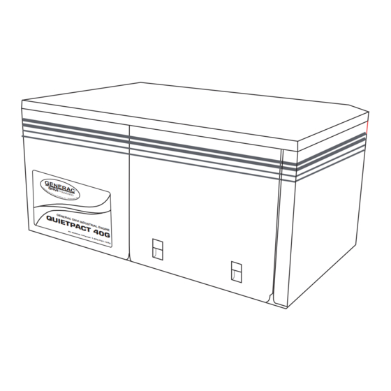
Page 22: Section 1 - General Information
Boulevard, Rexdale, Ontario, Canada, M9W 1R3. EQUIPMENT DESCRIPTION Instructions and information in this section pertain to Generac air-cooled generators. This generator is designed specifically for installing in recreational vehicles. This generator operates 120-volts, single- phase, 60-Hertz, AC electrical loads that require 30.0 amps. - Page 23 Section 1 – General Information QUIETPACT 40G Recreational Vehicle Generator Figure 1.2 – Major Features and Dimensions (Drawing No. 0D8716-C) Generac ® Power Systems, Inc. 21...
-
Page 24: Section 2 - Installation
The fol- lowing general rules apply: • Vehicle construction MUST be capable of support- ing the weight of the generator. 22 Generac ® Power Systems, Inc. • Whether the generator is mounted above the hori-... -
Page 25: Generator Restraint
• If the compartment is lined with galvanized steel, it may be constructed of any material. Generac rec- ommends that the compartment be constructed of 1/2-inch thick plywood (not strandboard), with the... -
Page 26: Sound Insulating Materials
One excellent insulating material is a 1- inch (25 mm) thick fiberglass having a 2-pound den- sity. When fiberglass is used, its coated side should face toward the compartment interior. 24 Generac ® Power Systems, Inc. DANGER Do not install sound insulation or any absorbent material on the compartment floor interior. -
Page 27: Compartment Floor Cutouts
307.4 OIL DRAIN 376.4 695 TYP. Section 2 – Installation DANGER Fuel lines and exhaust piping must not pene- trate into the vehicle living area. 32.2 59.2 259.7 176.6 63.5 Generac ® Power Systems, Inc. 25 5/16"-18 WELDNUTS (6 PLACES) -
Page 28: Cooling And Ventilating Air
® Power Systems, Inc. 2.3.2 TESTING THE INSTALLATION Generac recommends testing the installation to be sure adequate cooling airflow is available to the unit before placing the unit into service. If the unit shows signs of overheating, you will need to enlarge the air openings. -
Page 29: Fuel Tank
If the generator is to share the vehicle engine's tank, separate fuel pickup tubes are required for the engine and the generator. Generac recommends that you make the fuel pickup tube 2 to 3 inches (51 to 76 mm) shorter than the vehicle engine's pickup tube. -
Page 30: Mufflers And Spark Arrestors
(see Figures 2.11 and 2.12). Use only Generac supplied hardware. Substitution of parts may cause damage to the screen or a loose fit to the tailpipe. -
Page 31: Electrical Junction Box
• If you use metallic conduit, vapor seal the end of the conduit where it enters the junction box. Do this because flexible metallic conduit is not vapor- proof along its entire length. Generac 483.1 REMOTE PANEL CONNECTOR AC OUTPUT... -
Page 32: Isolating Different Power Sources
(Figure 2.15). Whichever method you use, you must be certain that both power sources are NOT connect- ed at the same time. Figure 2.13 – Installation With Isolation Receptacle 30 Generac ® Power Systems, Inc. The power supply cord must comply with all applic- able codes, standards and regulations. -
Page 33: Ground Fault Circuit Interrupters
FUEL 12.00" 12.00" WIRE LENGTH (mm) FUNCTION COLOR GROUND WHITE 12.0 (305) 12.0 (305) ENGINE RUN SIGNAL ORANGE 12.0 (305) 12 VDC YELLOW 12.0 (305) START BROWN 12.0 (305) STOP BLUE 12.0 (305) PRIME Generac ® Power Systems, Inc. 31... -
Page 34: Remote Start/Stop Panels
The generator engine is equipped with a high tem- perature switch. The switch has normally closed (N.C.) contacts. When the engine temperature is too high, switch contacts close, and the engine shuts down automatically. GENERAC RECOMMENDS THAT YOU TEST THE GENERATOR FOR ADEQUATE COOLING. -
Page 35: Installation Checklist
Check that hourmeter kit (if used) is installed properly. Check that any other options and accessories (if used) are installed properly. POST INSTALLATION TESTS Check that all tests are completed properly. ____________________________________________________ ______________________________________________________ ________________________________________________ Generac ® Power Systems, Inc. 33... -
Page 36: Appendix 1 - Notes
Appendix 1 – Notes QUIETPACT 40G Recreational Vehicle Generator 34 Generac ® Power Systems, Inc. -
Page 37: Appendix 2 - Troubleshooting
ON (or closed). 2. Reset and replace if necessary. 3. Set switch to GENERATOR. 4. Stop, then restart the engine (Hold Start switch for at least 2 seconds). 5. Contact a Generac Authorized Service Dealer. Generac ® Power Systems, Inc. 35... -
Page 38: Appendix 3 - Electrical Data
Appendix 3 — Electrical Data QUIETPACT 40G Recreational Vehicle Generator Electrical Schematic and Wiring Diagram – Drawing No. 0D8063-A BATTERY CHARGE WINDING WHITE GREEN NEUTRAL CONNECTION BY CUSTOMER 36 Generac ® Power Systems, Inc. BATTERY J1-1 J1-2 J1-3 J1-4 J1-5... - Page 39 Appendix 3 — Electrical Data QUIETPACT 40G Recreational Vehicle Generator Electrical Schematic and Wiring Diagram – Drawing No. 0D8063-A Generac ® Power Systems, Inc. 37...
-
Page 40: Appendix 4 - Exploded Views And Parts Lists
Appendix 4 — Exploded Views and Parts Lists QUIETPACT 40G Recreational Vehicle Generator Enclosure – Drawing No. 0D8352-E 38 Generac ® Power Systems, Inc. TO CARB... - Page 41 023484E 030340 0E0014 0E0017 0C7968 0E0361 0D8981 029451A 0D8628B Generac DESCRIPTION WASHER FLAT 3/8-M10" BLOCK, TERMINAL BATTERY POST STUD 3/8"-16 X 2"-1/4" BRASS 2.1' TAPE FOAM 1/8" X ½" SCREW HHTT M5-0.8 X 10 CUSTOMER CONNECTION HARNESS FOAM, AIR OUT COMPARTMENT SIDE...
- Page 42 Appendix 4 — Exploded Views and Parts Lists QUIETPACT 40G Recreational Vehicle Generator Generator – Drawing No. 0D8353-F 40 Generac ® Power Systems, Inc.
- Page 43 WASHER FLAT .281" I.D. X 1.50" O.D. WASHER LOCK M6-1/4" MUFFLER SCREW HHTT M6-1.0 X 12MM BOLT CARR 5/16"-18 X 2" NUT FLANG 5/16"-18 LOCK GASKET, EXHAUST NUT, HEX M8-1.25 SCREW HHC 5/16"-18 X 1-3/4" FILTER GASKET RV Generac ® Power Systems, Inc. 41...
- Page 44 Appendix 4 — Exploded Views and Parts Lists QUIETPACT 40G Recreational Vehicle Generator Control Panel – Drawing No. 0D8354-C 42 Generac ® Power Systems, Inc.
- Page 45 SCREW RHM #6-32 X 1/4" SIMS TIE WRAP UL 4" (NOT SHOWN) DECAL (NOT SHOWN) HARNESS (NOT SHOWN) BUSHING, SNAP 1.09" WASHER LOCK M3 WASHER FLAT M3 DEUTSCH, MOUNTING CLIP RIVET POP 0.125" LARGE FLANGE Generac ® Power Systems, Inc. 43...
- Page 46 Appendix 4 — Exploded Views and Parts Lists QUIETPACT 40G Recreational Vehicle Generator GN-220 H/SH Engine – Drawing No. 0D8355-C Part 1 44 Generac ® Power Systems, Inc.
- Page 47 SCREW PPHM M3-0.5 X 8MM ELBOW 45D STREET 1/8NPT RHMS #4-40 X 5/16" SEMS COTTER PIN ROD, CHOKE CONTROL BOOT CHOKE SOLENOID PLASTIC SCREW TAP-R #10-32 X 9/16" RHMS #4-40 X 1/4" SEMS ASSEMBLY, BI-METAL/HEATER SOLENOID, CHOKE Generac ® Power Systems, Inc. 45...
- Page 48 Appendix 4 — Exploded Views and Parts Lists QUIETPACT 40G Recreational Vehicle Generator GN-220 H/SH Engine – Drawing No. 0D8355-C Part 2 46 Generac ® Power Systems, Inc.
- Page 49 ROCKER ARM JAM NUT PUSH ROD GUIDE PLATE 1/4" NPT PIPE PLUG ROCKER COVER ASSEMBLY PLASTIC OIL FILL PLUG VALVE SPRING KEEPER BARBED ELBOW 90 1/4" NPT X 3/8" STUD M8-1.25 / 10MM X 30MM Generac ® Power Systems, Inc. 47...
-
Page 50: Appendix 5 - Warranty
Limited Warranties for Generac Power Systems, Inc.,” which is enclosed herewith on a separate sheet, also provided to you by Generac. The ECS Warranty applies only to the emission control system of your new engine. If there is any conflict in terms between the ECS Warranty and the Generac Warranty, the ECS Warranty shall apply except in circumstances where the Generac Warranty may provide a longer warranty period. -
Page 51: Emission Control System Warranty
Such use voids this ECS Warranty and shall be sufficient grounds for disallowing an ECS Warranty claim. Generac shall not be held liable hereunder for failures of any warranted parts of a Generac engine caused by the use of such an unapproved, add-on, modified, counterfeit and/or ‘grey market’... - Page 52 Generac Power Systems, Inc. (Generac) will, at its option, repair or replace any part which, upon examination, inspec- tion and testing by Generac or a Generac Authorized Warranty Service Facility, is found to be defective under normal use and service, in accordance with the warranty schedule set forth below. Any equipment that the purchaser/owner claims to be defective must be returned to and examined by the nearest Generac Authorized Warranty Service Facility.