Mitsubishi 4D68 Workshop Manual
Hide thumbs
Also See for 4D68:
- Workshop manual (79 pages) ,
- Workshop manual (71 pages) ,
- Workshop manual (4 pages)
Table of Contents
Advertisement
Quick Links
E
Mitsubishi Motors Corporation
ENGINE
4D68
CONTENTS
. . . . . . . . . . . . . . . . . . . . . . . . . . . . . . . . . . . . .
. . . . . . . . . . . . . . . . . . . . . . . . . . . . . . . . . . . . . . . . . .
. . . . . . . . . . . . . . . . . . . . . . . . . . . . . . . . . . . . . . . . . . . . . . . . .
. . . . . . . . . . . . . . . . . . . . . . . . . . . . . . . . . . . . . . . . . .
. . . . . . . . . . . . . . . . . . . . . . . . . . . . . . . . . . . . . . . . . . . . . . .
. . . . . . . . . . . . . . . . . . . . . . . . . . . . . . . . . . . . . . . . . . . . . . .
Dec. 1996
. . . . . . . . . . . . . . . . . . . . . . . . . . . .
. . . . . . . . . . . . . . . . . . . . . . . . . . . . . . . . .
. . . . . . . . . . . . . . . . . . . . . . . . . . . . .
. . . . . . . . . . . . . . . .
. . . . . . . . . . . . . . . . . . . . . . . . . . . . . .
. . . . . . . . . . . . . . . . . . . . . . . . . .
. . . . . . . . . . . . . . . . . . . . . . . . . . . . . . . .
. . . . . . . . . . . . . . . . . . . .
. . . . . . . . . . . . . . . . . . . . .
PWEE9609
11A-0-1
. . . . . .
. . .
. . . . .
. . .
Advertisement
Chapters
Table of Contents

Related Manuals for Mitsubishi 4D68


Summary of Contents for Mitsubishi 4D68
-
Page 1: Table Of Contents
11. PISTONS AND CONNECTING RODS 11A-11-1 ..... 12. CRANKSHAFT, CYLINDER BLOCK AND FLYWHEEL 11A-12-1 . . . Mitsubishi Motors Corporation Dec. 1996 PWEE9609... - Page 2 11A-0-2 NOTES Mitsubishi Motors Corporation Dec. 1996 PWEE9609...
-
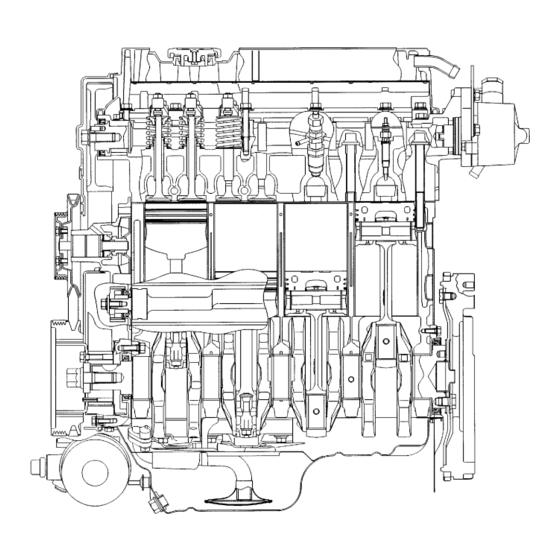
Page 3: Sectional View Of Engine
11A-0-3 4D68 ENGINE (E - W) - General Information GENERAL INFORMATION SECTIONAL VIEW OF ENGINE Mitsubishi Motors Corporation Dec. 1996 PWEE9609... -
Page 4: Sectional View Of Engine
11A-0-4 4D68 ENGINE (E - W) - General Information SECTIONAL VIEW OF ENGINE Mitsubishi Motors Corporation Dec. 1996 PWEE9609... -
Page 5: General Specifications
11A-0-5 4D68 ENGINE (E - W) - General Information GENERAL SPECIFICATIONS Descriptions Specifications Type Diesel engine Number of cylinders 4 in-line Combustion chamber Swirl chamber Total displacement dm 1.998 Cylinder bore mm 82.7 Piston stroke mm Compression ratio 22.4 Valve timing... -
Page 6: Specifications 11A-1-1
11A-1-1 4D68 ENGINE (E - W) - Specifications 1. SPECIFICATIONS SERVICE SPECIFICATIONS Item Standard value Limit Drive belt and glow plug Glow plug resistance W Timing belt Timing belt deflection mm 4.0 - 5.0 Timing belt “B” deflection mm 5.0 - 7.0... - Page 7 11A-1-2 4D68 ENGINE (E - W) - Specifications Item Standard value Limit Oil cooler by-pass valve dimension (L) [by-pass hole closing temperature 40.0 (97 - 103°C or more)] mm Oil pump side clearance Drive gear 0.08 - 0.14 Driven gear 0.06 - 0.12...
-
Page 8: Rework Dimensions
11A-1-3 4D68 ENGINE (E - W) - Specifications REWORK DIMENSIONS Item Standard value Limit Cylinder head, valves and valve springs Cylinder head oversize valve guide hole 0.05 O.S. 13.050 - 13.068 (both intake and exhaust) mm 0.25 O.S. 13.250 - 13.268 0.50 O.S. -
Page 9: Torque Specifications
11A-1-4 4D68 ENGINE (E - W) - Specifications TORQUE SPECIFICATIONS Items Drive belt and glow plug Oil level gauge guide bolt Pulley bolt (for power steering pump drive) Alternator brace bolt Lock bolt Adjusting bolt Alternator pivot nut Crankshaft pulley bolt... - Page 10 11A-1-5 4D68 ENGINE (E - W) - Specifications Items Injection nozzle Fuel injection pump bracket nut Intake and exhaust manifold Air temperature sensor Air intake fitting bolt EGR valve bolt EGR pipe bolt and nut Turbocharger heat protector bolt Exhaust fitting heat protector bolt Water pipe “A”...
- Page 11 11A-1-6 4D68 ENGINE (E - W) - Specifications Items Adjusting nut Camshaft bearing cap bolt M8 ¢ 25, M8 ¢ 40 M8 ¢ 55 Cylinder head, valves and valve springs Cylinder head bolt ¯ Fully loosen ¯ 40 + 90° + 90°...
-
Page 12: New Tightening Method - By Use Of Bolts To Be Tightened In Plastic Area
11A-1-7 4D68 ENGINE (E - W) - Specifications NEW TIGHTENING METHOD - BY USE OF BOLTS TO BE TIGHTENED IN PLASTIC AREA A new type of bolts, to be tightened in plastic area, is currently used some parts of the engine. The tightening method for the bolts is different from the conventional one. -
Page 13: Form-In-Place Gasket
11A-1-8 4D68 ENGINE (E - W) - Specifications FORM-IN-PLACE GASKET The engine has several areas where the form-in-place gasket (FIPG) is in use. To ensure that the gasket fully serves its purpose, it is necessary to observe some precautions when applying the gasket. Bead size, continuity and location are of paramount importance. -
Page 14: Special Tools
11A-2-1 4D68 ENGINE (E - W) - Special Tools 2. SPECIAL TOOLS Tool Number Name MB990767 End yoke holder Holding camshaft sprocket or fuel injection pump when loosening or tightening bolts. Use with MD998719 MB991603 Bearing installer A guide for removal and installation of... - Page 15 11A-2-2 4D68 ENGINE (E - W) - Special Tools Tool Number Name MD998375 Crankshaft front oil Installation of crankshaft front oil seal seal installer MD998388 Injection pump Removal of injection pump sprocket sprocket puller MD998702 Connecting-rod Replacement of connecting-rod small-end...
- Page 16 11A-2-3 4D68 ENGINE (E - W) - Special Tools Tool Number Name MD998776 Crankshaft rear oil Installation of crankshaft rear oil seal seal installer (Use with MB990938) MD998778 Crankshaft Removal of crankshaft sprocket sprocket puller MD998781 Flywheel stopper Holding of flywheel and drive plate...
-
Page 17: Drive Belt And Glow Plug
11A-3-1 4D68 ENGINE (E - W) - Drive Belt and Glow Plug 3. DRIVE BELT AND GLOW PLUG REMOVAL AND INSTALLATION 13 Nm 1.8 Nm 18 Nm 10 Nm 44 Nm 23 Nm 9 Nm 25 Nm DEN0885 Removal steps 1. - Page 18 11A-3-2 4D68 ENGINE (E - W) - Drive Belt and Glow Plug REMOVAL SERVICE POINTS AA" GLOW PLUG REMOVAL (1) When removing the glow plug, you may loosen using a tool up to the point where one or more threads are left in engagement.
-
Page 19: Timing Belt
11A-4-1 4D68 ENGINE (E - W) - Timing Belt 4. TIMING BELT REMOVAL AND INSTALLATION 11 Nm 48 Nm 11 Nm 45 Nm 88 Nm 9 Nm 49 Nm 83 Nm 48 Nm 13 Nm 18 Nm 11 Nm 15 16... -
Page 20: Removal Service Points
11A-4-2 4D68 ENGINE (E - W) - Timing Belt REMOVAL SERVICE POINTS AA" TIMING BELT REMOVAL (1) Using chalk, etc., mark an arrow on the back of the timing belt to indicate the direction of rotation. This is to ensure correct installation of the belt in case it is reused. -
Page 21: 4D68 Engine (E
11A-4-3 4D68 ENGINE (E - W) - Timing Belt AE" CRANKSHAFT BOLT LOOSENING MD998781 DEN0743 AF" CRANKSHAFT SPROCKET REMOVAL MD998778 DEN0744 AG" OIL PUMP SPROCKET REMOVAL (1) Before loosening the oil pump sprocket nut (flange nut), remove the timing belt and then the plug at the left side... -
Page 22: Installation Service Points
11A-4-4 4D68 ENGINE (E - W) - Timing Belt AI" COUNTERBALANCE SHAFT SPROCKET REMOVAL MD998785 DEN0746 AJ" CRANKSHAFT SPROCKET “B” REMOVAL MD998778 DEN0747 INSTALLATION SERVICE POINTS seal "AA SPACER INSTALLATION Spacer (1) Install the spacer with the chamfered end toward the oil seal. - Page 23 11A-4-5 4D68 ENGINE (E - W) - Timing Belt (3) Make sure that the pulley center and the bolt center are located as shown in the illustration. Timing belt “B” Tensioner “B” Tensioner pulley center DEN0749 (4) More the tensioner “B” in the direction of arrow while lifting with a finger to give a sufficient tension to the tension side of the timing belt.
-
Page 24: Timing Belt Installation
11A-4-6 4D68 ENGINE (E - W) - Timing Belt "FA INJECTION PUMP SPROCKET NUT TIGHTENING MD998719 MB990767 DEN0754 "GA CAMSHAFT SPROCKET BOLT TIGHTENING MB990767 MD998719 DEN0755 "HA TIMING BELT TENSIONER INSTALLATION (1) Set the tensioner spring ends against the tensioner bracket and the projection of the injection pump bracket. - Page 25 11A-4-7 4D68 ENGINE (E - W) - Timing Belt (4) Remove the plug on the cylinder block and insert a Phillips screwdriver [shank diameter 8 mm] through the hole. If it can be inserted as deep as 60 mm or more, the timing marks are correctly aligned.
- Page 26 11A-4-8 4D68 ENGINE (E - W) - Timing Belt INSPECTION TIMING BELTS The timing belts must be checked closely. Should the following defects be evident, replace the belt with a new one. (1) Hardened back surface rubber Glossy, non-elastic, and so hard that no mark is produced even when scratched by fingernails.
-
Page 27: Glow Plug, Fuel Injection Pump And Injection Nozzle
11A-5-1 4D68 ENGINE (E - W) - Glow Plug, Fuel Injection Pump And Injection Nozzle 5. GLOW PLUG, FUEL INJECTION PUMP AND INJECTION NOZZLE REMOVAL AND INSTALLATION 5 Nm 5 Nm 29 Nm 29 Nm 29 Nm 54 Nm 18 Nm... - Page 28 11A-5-2 4D68 ENGINE (E - W) - Glow Plug, Fuel Injection Pump And Injection Nozzle REMOVAL SERVICE POINTS Delivery AA" INJECTION PIPE REMOVAL holder (1) When loosening the union nuts on the injection pump, hold the delivery valve holder on the fuel injection pump head with a spanner to prevent it from rotating along with the union nut.
- Page 29 11A-5-3 4D68 ENGINE (E - W) - Glow Plug, Fuel Injection Pump And Injection Nozzle INSTALLATION SERVICE POINTS "AA NOZZLE GASKET / HOLDER GASKET INSTALLATION Holder gasket (1) Clean nozzle holder installation areas of the cylinder head. (2) Fit a new nozzle gasket and holder gasket into the nozzle Nozzle holder hole in the cylinder head.
-
Page 30: Intake And Exhaust Manifolds
11A-6-1 4D68 ENGINE (E - W) - Intake and Exhaust Manifolds 6. INTAKE AND EXHAUST MANIFOLDS REMOVAL AND INSTALLATION 17 Nm 24 Nm 14 Nm 11 Nm 17 Nm 14 Nm 16 Nm 16 Nm 10 Nm 17 Nm 11 Nm... -
Page 31: Oil Return Pipe Bolt
11A-6-2 4D68 ENGINE (E - W) - Intake and Exhaust Manifolds INSTALLATION SERVICE POINTS "AA OIL RETURN PIPE GASKET INSTALLATION Oil return pipe (1) Install the oil return pipe gasket in such a way that its projection is located at the illustrated position. -
Page 32: Water Pump, Thermostat, Hose And Pipes
11A-7-1 4D68 ENGINE (E - W) - Water Pump, Thermostat, Hose and Pipes 7. WATER PUMP, THERMOSTAT, HOSE AND PIPES REMOVAL AND INSTALLATION 16 Nm 22 Nm 9 Nm 45 Nm 23 Nm 23 Nm 11 Nm 12 Nm 12 Nm... - Page 33 11A-7-2 4D68 ENGINE (E - W) - Water Pump, Thermostat, Hose and Pipes INSTALLATION SERVICE POINTS "AA THERMOSTAT HOUSING INSTALLATION (1) Apply a 3 mm bead of form-in-place gasket (FIPG) to the mounting surface. Specified sealant: Mitsubishi Genuine Part No. MD970389 or equivalent.
-
Page 34: 4D68 Engine (E - W) - Specifications
11A-7-3 4D68 ENGINE (E - W) - Water Pump, Thermostat, Hose and Pipes "FA ENGINE COOLANT TEMPERATURE GAUGE UNIT INSTALLATION (1) If the water temperature sensor is to be reused, apply the specified sealant to its thread. Specified sealant: 3M Nut Locking Part No. 4171 or equivalent. -
Page 35: Rocker Arms, Rocker Shaft And Camshaft . . . 11A-8-1
11A-8-1 4D68 ENGINE (E - W) - Rocker Arms, Rocker Shaft and Camshaft 8. ROCKER ARMS, ROCKER SHAFT AND CAMSHAFT REMOVAL AND INSTALLATION 6 Nm 29 Nm 20 Nm 15 Nm 20 Nm 29 Nm 29 Nm Apply engine oil to all moving parts before installation. - Page 36 11A-8-2 4D68 ENGINE (E - W) - Rocker Arms, Rocker Shaft and Camshaft INSTALLATION SERVICE POINTS Camshaft sprocket side "AA CAMSHAFT BEARING CAP INSTALLATION (1) Install the bearing caps in the designated position confirming the identification numbers stamped on the cap front.
-
Page 37: Valve Clearance Adjustment
11A-8-3 4D68 ENGINE (E - W) - Rocker Arms, Rocker Shaft and Camshaft VALVE CLEARANCE ADJUSTMENT (1) Turn the crankshaft clockwise and align the timing mark on camshaft sprocket with that on the injection pump Timing mark Camshaft bracket. sprocket... - Page 38 11A-8-4 4D68 ENGINE (E - W) - Rocker Arms, Rocker Shaft and Camshaft (5) While holding the adjusting screw with a screwdriver, tighten the lock nut. (6) Rotate clockwise the crankshaft one complete turn (360 degrees). (7) Adjust the valve clearance at the points shown in the illustration.
-
Page 39: Cylinder Head, Valves And Valve Springs
11A-9-1 4D68 ENGINE (E - W) - Cylinder Head, Valves and Valve Springs 9. CYLINDER HEAD, VALVES AND VALVE SPRINGS REMOVAL AND INSTALLATION Apply engine oil to all moving parts before installation. DEN0777 Removal steps AA" "EA 1. Cylinder head bolt AC"... - Page 40 11A-9-2 4D68 ENGINE (E - W) - Cylinder Head, Valves and Valve Springs REMOVAL SERVICE POINTS AA" CYLINDER HEAD BOLT REMOVAL (1) Using a 12 mm - 12 points socket wrench, loosen the cylinder head bolts. MB991654 DEN0778 AB" RETAINER LOCK REMOVAL (1) Store removed valves, springs and other parts, tagged to indicate their cylinder No.
-
Page 41: Cylinder Head Bolt Installation
11A-9-3 4D68 ENGINE (E - W) - Cylinder Head, Valves and Valve Springs "CA RETAINER LOCK INSTALLATION (1) The valve spring, if excessively compressed, causes the bottom end of the retainer to be in contact with, and damage, the stem seal. -
Page 42: Inspecting Cylinder Head
11A-9-4 4D68 ENGINE (E - W) - Cylinder Head, Valves and Valve Springs (3) Using the special tool (MB991654) and according to the tightening sequence, tighten the bolts to the specified Timing belt side torque. Tightening torque: 90 Nm (4) Loosen all bolts fully. - Page 43 11A-9-5 4D68 ENGINE (E - W) - Cylinder Head, Valves and Valve Springs VALVE (1) Check the valve face for correct contact. If incorrect, reface using a valve refacer. Valve seat contact should be maintained uniform at the center of valve face.
- Page 44 11A-9-6 4D68 ENGINE (E - W) - Cylinder Head, Valves and Valve Springs (2) Install the valve and, while pressing the valve against Valve stem end the valve seat, measure the valve stem projection between the valve stem end and the valve spring seat seating Valve stem surface.
- Page 45 11A-9-7 4D68 ENGINE (E - W) - Cylinder Head, Valves and Valve Springs VALVE GUIDE REPLACEMENT PROCEDURE Press Removal (1) Using the special tool and a press, remove the valve guide toward the cylinder head gasket surface. Push rod (2) Rebore the valve guide hole to the new oversize valve contained in guide outside diameter.
-
Page 46: Front Case, Counterbalance Shafts And Oil Pan
11A-10-1 4D68 ENGINE (E - W) - Front Case, Counterbalance Shafts and Oil Pan 10. FRONT CASE, COUNTERBALANCE SHAFTS AND OIL PAN REMOVAL AND INSTALLATION Apply engine oil to all moving parts before installation. 24 Nm 10 Nm 10 Nm... -
Page 47: Plug
11A-10-2 4D68 ENGINE (E - W) - Front Case, Counterbalance Shafts and Oil Pan REMOVAL SERVICE POINTS AA" OIL PAN REMOVAL (1) Knock the special tool deeply between the oil pan and the cylinder block. (2) Hitting the side of the special tool, slide the special tool MD998727 along the oil pan to remove it. - Page 48 11A-10-3 4D68 ENGINE (E - W) - Front Case, Counterbalance Shafts and Oil Pan AE" RIGHT COUNTERBALANCE SHAFT REAR BEARING / LEFT COUNTERBALANCE SHAFT MB991603 REAR BEARING REMOVAL (1) Using the special tool, remove two rear bearings from the cylinder block.
- Page 49 11A-10-4 4D68 ENGINE (E - W) - Front Case, Counterbalance Shafts and Oil Pan (4) Insert the installer aligning with the guide pin and install the bearing. MD998705 Guide pin 6EN0775 MD998705 6EN0776 "CA COUNTERBALANCE SHAFT FRONT BEARING INSTALLATION (1) Remove the rear bearing installing portion from the special tool.
- Page 50 11A-10-5 4D68 ENGINE (E - W) - Front Case, Counterbalance Shafts and Oil Pan (5) Insert the installer aligning with the guide pin and install the bearing. MD998705 Guide pin 6EN0775 6EN0778 "DA OIL PUMP OIL SEAL INSTALLATION Socket wrench...
- Page 51 11A-10-6 4D68 ENGINE (E - W) - Front Case, Counterbalance Shafts and Oil Pan "GA OIL PUMP DRIVEN GEAR / OIL PUMP DRIVE GEAR INSTALLATION (1) Apply engine oil amply to the gears and line up the Alignment mark alignment marks.
-
Page 52: Front Case Bolt
11A-10-7 4D68 ENGINE (E - W) - Front Case, Counterbalance Shafts and Oil Pan "JA PLUG INSTALLATION MD998162 (1) Fit a new O-ring in the front case. (2) Tighten the plug to the specified torque using the special tool. MD998783 6EN0909 "KA OIL PRESSURE SWITCH INSTALLATION... - Page 53 11A-10-8 4D68 ENGINE (E - W) - Front Case, Counterbalance Shafts and Oil Pan COUNTERBALANCE SHAFT (1) Check the oil holes for clogging. (2) Check the journals for seizure, damage, and contact with bearing. If there is anything wrong with the journal, replace the counterbalance shaft, bearing or front case assembly.
-
Page 54: Pistons And Connecting Rods
11A-11-1 4D68 ENGINE (E - W) - Pistons and Connecting Rods 11. PISTONS AND CONNECTING RODS REMOVAL AND INSTALLATION Apply engine oil to all moving parts before installation. DEN0771 Removal steps "FA 1. Connecting rod cap nut 8. Oil ring AA"... - Page 55 11A-11-2 4D68 ENGINE (E - W) - Pistons and Connecting Rods REMOVAL SERVICE POINTS AA" CONNECTING ROD CAP REMOVAL (1) Mark the cylinder number on the side of the connecting rod big end for correct reassembly. Cylinder No. DEN0050 INSTALLATION SERVICE POINTS "AA PISTON PIN / PISTON / CONNECTING ROD...
- Page 56 11A-11-3 4D68 ENGINE (E - W) - Pistons and Connecting Rods "DA PISTON AND CONNECTING ROD ASSEMBLY INSTALLATION Coil expander joint No. 1 (1) Liberally coat engine oil on the circumference of the piston, piston ring, and oil ring. (2) Arrange the piston ring and oil ring gaps as shown in...
- Page 57 11A-11-4 4D68 ENGINE (E - W) - Pistons and Connecting Rods "FA CONNECTING ROD CAP NUT INSTALLATION Caution If the cylinder head has been installed before installing the connecting rod cap nut, be sure to remove the spark plugs. (1) Since the connecting rod cap bolts and nuts are torqued using the plastic area tightening method, the bolts should be examined BEFORE reuse.
- Page 58 11A-11-5 4D68 ENGINE (E - W) - Pistons and Connecting Rods INSPECTION PISTON RING (1) Check for side clearance. If the limit is exceeded, replace the ring or piston, or both. 5EN0066 (2) In the case of semi-keystone type piston rings, check the ring to ring groove clearance as illustrated.
- Page 59 11A-11-6 4D68 ENGINE (E - W) - Pistons and Connecting Rods CONNECTING ROD BUSHING REPLACEMENT Removal (1) Using the special tool, remove the bushing. MD998702 Bushing DEN204 (2) Using the special tool, install the bushing, aligning the Installation oil hole of the bushing with the oil hole at the small end of the connecting rod.
-
Page 60: Crankshaft, Cylinder Block And Flywheel . . . 11A-12-1
11A-12-1 4D68 ENGINE (E - W) - Crankshaft, Cylinder Block and Flywheel 12. CRANKSHAFT, CYLINDER BLOCK AND FLYWHEEL REMOVAL AND INSTALLATION 132 Nm “A” 11 Nm 11 Nm 32 Nm Apply engine oil to all moving parts before installation. DEN0893 Removal steps 1. - Page 61 11A-12-2 4D68 ENGINE (E - W) - Crankshaft, Cylinder Block and Flywheel INSTALLATION SERVICE POINTS No.3 "AA CRANKSHAFT BEARING INSTALLATION When the bearing needs replacing, select and install a proper No.2 bearing by the following procedure. (1) Measure the crankshaft journal diameter and confirm its No.4...
- Page 62 11A-12-3 4D68 ENGINE (E - W) - Crankshaft, Cylinder Block and Flywheel "BA BEARING CAP / BEARING CAP BOLT INSTALLATION (1) Install the bearing caps so that their arrows are directed to the timing belt side. (2) Before installing the bearing cap bolts, check that the shank length of each bolt meets the limit.
- Page 63 11A-12-4 4D68 ENGINE (E - W) - Crankshaft, Cylinder Block and Flywheel "CA OIL SEAL INSTALLATION MB990938 MD998776 6EN0709 "DA OIL SEAL CASE INSTALLATION Specified sealant: Mitsubishi Genuine Part No. MD970389 or equivalent 6EN0626 INSPECTION Plastic gauge CRANKSHAFT OIL CLEARANCE (PLASTIC GAUGE...
- Page 64 11A-12-5 4D68 ENGINE (E - W) - Crankshaft, Cylinder Block and Flywheel CYLINDER BLOCK (1) Visually check for cracks, rust, and corrosion, and inspect the cylinder block using a flaw detecting agent. Rectify defects where possible or replace the cylinder block.
- Page 65 11A-12-6 4D68 ENGINE (E - W) - Crankshaft, Cylinder Block and Flywheel (4) Bore all cylinders to the calculated boring finish dimension. Caution To prevent distortion that may result from temperature rise during honing, bore cylinders, in the order of No.
- Page 66 11A-12-7 4D68 ENGINE (E - W) - Crankshaft, Cylinder Block and Flywheel INSPECTION Y direction (1) After removing the cylinder sleeve, check the cylinder block sleeve hole surface. X direction If there is damage, insufficient interference-fit-margin or other problems, bore the cylinder block sleeve hole to an oversize.
- Page 67 11A-12-8 4D68 ENGINE (E - W) - Crankshaft, Cylinder Block and Flywheel (5) Chamfer the cylinder sleeve top end as illustrated. 0.5 mm Cylinder sleeve 30° DEN244 (6) The service cylinder sleeve has the I.D. machined to 81.5 to 81.7 mm. After installation of the sleeve, therefore, hone the I.D.
- Page 68 NOTES...