Table of Contents
Advertisement
Advertisement
Table of Contents

Related Manuals for Integra DTR-80.1


Summary of Contents for Integra DTR-80.1
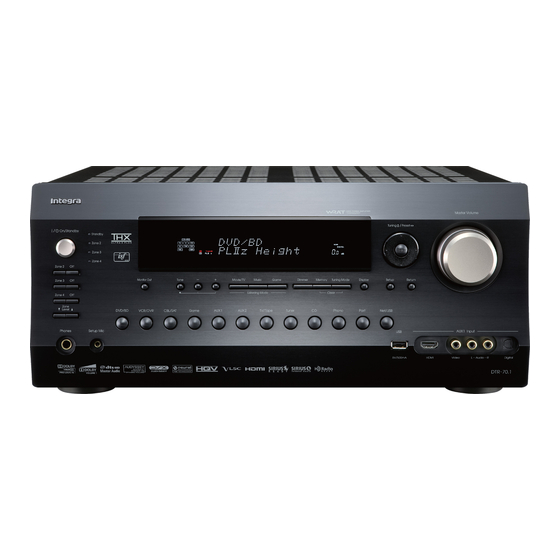
- Page 1 AV Receiver DTR-70.1 DTR-80.1 Instruction Manual...
-
Page 2: Important Safety Instructions
WARNING: WARNING AVIS RISK OF ELECTRIC SHOCK RISQUE DE CHOC ELECTRIQUE TO REDUCE THE RISK OF FIRE OR ELECTRIC DO NOT OPEN NE PAS OUVRIR SHOCK, DO NOT EXPOSE THIS APPARATUS TO The lightning flash with arrowhead symbol, within an RAIN OR MOISTURE. -
Page 3: Precautions
Precautions 1. Recording Copyright—Unless it’s for personal use For U.S. models only, recording copyrighted material is illegal with- FCC Information for User out the permission of the copyright holder. CAUTION: 2. AC Fuse—The AC fuse inside the unit is not user- The user changes or modifications not expressly serviceable. -
Page 4: Supplied Accessories
Supplied Accessories Thank you for purchasing an Integra AV receiver. Please read this manual thoroughly before making con- nections and plugging in the unit. Following the instructions in this manual will enable you Make sure you have the following accessories: to obtain optimum performance and listening enjoyment from your new AV receiver. -
Page 5: Table Of Contents
Looking up for Remote Control Code ....... 148 Digital Audio Input Setup ..........53 Entering Remote Control Codes....... 150 Analog Audio Input Setup ........... 54 Remote Control Codes for Integra/Onkyo Speaker Settings............54 Components Connected via ......151 TV Format Setup (Australian models)......56 Resetting Remote Mode Buttons...... -
Page 6: Features
HDMI, the HDMI logo and High Definition Multimedia Inter- • 6 Digital Inputs (3 Optical/3 Coaxial) (DTR-70.1) face are trademarks or registered trademarks of HDMI Licens- • 7 Digital Inputs (4 Optical/3 Coaxial) (DTR-80.1) ing, LLC. • Universal Port for UP-A1 (Dock for the iPod)/HD Radio™... - Page 7 Features—Continued This product incorporates copyright protection technology that is protected by U.S. patents and other intellectual property rights. Use of this copyright protection technology must be HD Radio™ and the HD Radio Ready logo are proprietary authorized by Macrovision Corporation, and is intended for trademarks of iBiquity Digital Corporation.
-
Page 8: Front & Rear Panels
Front & Rear Panels Front Panel The actual front panel has various logos printed on it. They are not shown here for clarity. The page numbers in parentheses show where you can find the main explanation for each item. On/Standby button (45) Display This button is used to set the AV receiver to On or See “Display”... - Page 9 Front & Rear Panels—Continued The page numbers in parentheses show where you can find the main explanation for each item. Display button (65) Input selector buttons (64) This button is used to display various information These buttons are used to select from the following about the currently selected input source.
-
Page 10: Display
Front & Rear Panels—Continued Display For detailed information, see the pages in parentheses. Speaker/channel indicators NETWORK indicator (127) Indicate the speaker channels used by the current Lights when the Net input selector is selected. listening mode. Tuning indicators The following abbreviations indicate which audio RDS (Australian models) (82): channels are outputted for the current listening Lights when tuned to a radio station that supports... -
Page 11: Rear Panel
Digital OPTICAL IN 1 and 2 (DTR-70.1) RS232 Digital OPTICAL IN 1, 2, and 3 (DTR-80.1) Terminal for control. These optical digital audio inputs are for connecting HDMI IN 1–6, OUT MAIN, and OUT SUB components with optical digital audio outputs, such (DTR-70.1) -
Page 12: Monitor Out
MULTI CH input: FRONT L/R, CENTER, video input on a TV in Zone 2. SUBWOOFER, SURR L/R, and SURR BACK PC INPUT ANALOG RGB (DTR-80.1) This input terminal is for connecting a personal This analog multichannel input is for connecting a computer with an analog RGB output. - Page 13 Front & Rear Panels—Continued FRONT L/R, CENTER, SURR/ZONE 4 L/R, SURR BACK/ZONE 3 L/R, FRONT HIGH L/R, and FRONT WIDE/ZONE 2 L/R These terminal posts are for connecting the front L/R, center, surround/zone 4 L/R, surround back/zone 3 L/R, front high L/R, and front wide/zone 2 L/R speakers.
-
Page 14: Remote Controller
(page 150), or when you want to operate an Inte- gra/Onkyo component without connection, point the remote controller at the other component to use it. • When you want to operate an Integra/Onkyo compo- nent with connection or an -compatible component connected via HDMI (pages 152 and 153), point the remote controller at the AV receiver’s remote... -
Page 15: Controlling The Av Receiver
Remote Controller—Continued Controlling the AV Receiver For detailed information, see the pages in parentheses. To control the AV receiver, press the [Receiver] but- Standby button (45) ton to select Receiver mode. Sets the AV receiver to Standby. You can also use the remote controller to control your On button (45) DVD/BD player, CD player, and other components. - Page 16 Remote Controller—Continued ■ Controlling the tuner To control the AV receiver’s tuner, press the [Tuner] (or [Receiver]) button. You can select AM or FM by pressing the [Tuner] button repeatedly. Arrow [ ]/[ ] buttons Used to tune into radio stations. D.TUN button (69) (Tuner remote mode only) Selects the Direct tuning mode.
-
Page 17: About Home Theater
About Home Theater Enjoying Home Theater Thanks to the AV receiver’s superb capabilities, you can enjoy surround sound with a real sense of movement in your own home—just like being in a movie theater or concert hall. With DVDs you can enjoy DTS and Dolby Digital. With analog or digital TV, you can enjoy Dolby Pro Logic IIx, DTS Neo:6, or Onkyo’s original DSP listening modes. -
Page 18: Connecting The Av Receiver
Connecting the AV receiver Connecting Your Speakers Speaker Configuration For 9.2-channel surround-sound playback, you need nine speakers and two powered subwoofers. The following table indicates the channels you should use depending on the number of speakers that you have. Number of speakers: ✓... - Page 19 Connecting the AV receiver—Continued Using Dipole Speakers Speaker Connection Precautions You can use dipole speakers for the surround left and Read the following before connecting your speakers: right, surround back left and right speakers. Dipole • You can connect speakers with an impedance of speakers output the same sound in two directions.
- Page 20 Connecting the AV receiver—Continued Connecting the Speaker Cables 1/2" to 5/8" Strip 1/2" to 5/8" (12 to Fully insert the bare (12 to 15 mm) 15 mm) of insulation wires. from the ends of the speaker cables, and twist the bare wires tightly, as shown.
-
Page 21: Bi-Amping The Front Speakers
Connecting the AV receiver—Continued Bi-amping Speaker Hookup Bi-amping the Front Speakers The FRONT L/R and SURR BACK/ZONE 3 L/R termi- Connect the AV receiver’s FRONT R positive (+) nal posts can be used with front speakers and surround terminal to the right speaker’s positive (+) Woofer back speakers respectively, or bi-amped to provide sepa- (low) terminal. -
Page 22: Bridging The Front Speakers
Connecting the AV receiver—Continued Bridged Speaker Hookup Bridging the Front Speakers The FRONT L/R and SURR BACK/ZONE 3 L/R ter- Connect the AV receiver’s FRONT R positive (+) minal posts can be used with front speakers and surround terminal to the right speaker’s positive (+) ter- back speakers respectively, or bridged together to pro- minal. -
Page 23: Connecting Passive Subwoofers
Connecting the AV receiver—Continued Connecting Passive Subwoofers The FRONT WIDE/ZONE 2 L/R terminal posts can be used with front wide speakers or passive subwoofers. • Once you’ve connected the passive subwoofers shown below and turned on the AV receiver, you must set the “Passive Subwoofer”... -
Page 24: Connecting Antenna
Connecting the AV receiver—Continued If you cannot achieve good reception with the supplied Connecting Antenna indoor FM antenna, try a commercially available out- This section explains how to connect the supplied indoor door FM antenna instead (see page 25). FM antenna and AM loop antenna, and how to connect commercially available outdoor FM and AM antennas. - Page 25 Connecting the AV receiver—Continued Connecting an Outdoor FM Antenna Connecting an Outdoor AM Antenna If you cannot achieve good reception with the supplied If good reception cannot be achieved using the supplied indoor FM antenna, try a commercially available out- AM loop antenna, an outdoor AM antenna can be used door FM antenna instead.
-
Page 26: About Av Connections
Connecting the AV receiver—Continued AV Connection Color Coding About AV Connections RCA-type AV connections are usually color-coded: red, • Before making any AV connections, read the manuals white, and yellow. Use red plugs to connect right-chan- supplied with your other AV components. nel audio inputs and outputs (typically labeled “R”). -
Page 27: Connecting Components With Hdmi
Audio, DTS-HD Master Audio) Your DVD/BD players must also support HDMI output of the above audio formats. ■ Integra/Onkyo for System Control , which stands for Remote Interactive over HDMI, is the name of the system control function found on Inte- gra/Onkyo components. -
Page 28: Audio Signals
Connecting the AV receiver—Continued Making HDMI Connections Step 1: Use HDMI cables to connect the AV receiver’s HDMI jacks to your HDMI-compatible DVD/BD player, TV, projec- tor, and so on. Step 2: Assign each HDMI IN to an input selector in the HDMI Input Setup (see page 51). ■... -
Page 29: Connecting Both Audio & Video
Connecting the AV receiver—Continued Connecting Both Audio & Video By connecting both the audio and video outputs of your DVD/BD player and other AV components to the AV receiver, you can select both the audio and video simultaneously simply by selecting the appropriate input source on the AV receiver. - Page 30 Connecting the AV receiver—Continued ■ “Monitor Out” Setting Set to “Both”, “Both(Main)” or “Both(Sub)” With the “Monitor Out” setting set to “Both”, DVD/BD player, etc. Video Signal Flow Chart “Both(Main)” or “Both(Sub)” (see page 49), video input signals flow through the AV receiver as shown, with composite video, S-Video, and Composite S-Video...
- Page 31 Connecting the AV receiver—Continued Audio Connection Formats DVD/BD player, etc. Audio equipment can be connected to the AV Audio Signal Flow Chart receiver by using any of the following audio con- nection formats: analog, optical, coaxial, analog multichannel, or HDMI. Analog Multichannel Optical...
-
Page 32: Connecting A Tv Or Projector
DIGITAL COAXIAL IN 2 (VCR/DVR) Digital coaxial output DIGITAL OPTICAL IN 1 (GAME) (DTR-70.1) ⇐ Digital optical output DIGITAL OPTICAL IN 2 (TV/TAPE) (DTR-80.1) When you use connection you need to assign the digital (DTR-70.1) When you use connection audio input (see page 53). -
Page 33: Connecting A Dvd Player
Connecting the AV receiver—Continued Connecting a DVD Player See “Connecting Components with HDMI” on page 27 for HDMI connection information. Step 1: Video Connection Choose a video connection that matches your DVD player ( , , or , and then make the connection. You must connect the AV receiver to your TV via the same type of connection. - Page 34 Connecting the AV receiver—Continued Hooking Up the Multichannel Input If your DVD player supports multichannel audio formats such as DVD-Audio and Super Audio CD, and it has a multi- channel analog audio output, you can connect it to the AV receiver’s multichannel input. Use a multichannel analog audio cable, or several normal audio cables, to connect the AV receiver’s MULTI CH: FRONT L/R, CENTER, SURR L/R, SURR BACK L/R, and SUBWOOFER jacks to the 7.1-channel analog audio output on your DVD player.
-
Page 35: Connecting A Vcr Or Dvd Recorder For Playback
Connecting the AV receiver—Continued Connecting a VCR or DVD Recorder for Playback With this hookup, you can use your VCR’s tuner to listen to your favorite TV programs via the AV Hint! receiver, useful if your TV has no audio outputs. Step 1: Video Connection Choose a video connection that matches your VCR or DVD recorder ( , , or... -
Page 36: Connecting A Vcr Or Dvd Recorder For Recording
Connecting the AV receiver—Continued Connecting a VCR or DVD Recorder for Recording Step 1: Video Connection Choose a video connection that matches your VCR or DVD recorder ( ), and then make the connection. The video source to be recorded must be connected to the AV receiver via the same type of connection. Step 2: Audio Connection Make the audio connection Connection... -
Page 37: Connecting A Satellite, Cable, Terrestrial Set-Top Box, Or Other Video Source
Connecting the AV receiver—Continued Connecting a Satellite, Cable, Terrestrial Set-top box, or Other Video Source With this hookup, you can use your satellite or cable receiver to listen to your favorite TV programs Hint! via the AV receiver, useful if your TV has no audio outputs. Step 1: Video Connection Choose a video connection that matches the video source ( , , or... -
Page 38: Connecting A Game Console
Connecting the AV receiver—Continued Connecting a Game Console Step 1: Video Connection Choose a video connection that matches your game console ( , , or , and then make the connection. You must connect the AV receiver to your TV with the same type of connection. Step 2: Audio Connection Choose an audio connection that matches your game console ( ), and then make the connection. -
Page 39: Connecting A Camcorder Or Other Device
Connecting the AV receiver—Continued Connecting a Camcorder or Other Device Step 1: Video Connection Make the connection Step 2: Audio Connection Choose an audio connection that matches your camcorder ( ), and then make the connection. Connection AV receiver Signal flow Camcorder etc. -
Page 40: Connecting A Cd Player Or Turntable
Analog audio L/R output ⇐ DIGITAL COAXIAL IN 2 (VCR/DVR) Digital coaxial output DIGITAL OPTICAL IN 2 (CD) (DTR-70.1) ⇐ Digital optical output DIGITAL OPTICAL IN 3 (CD) (DTR-80.1) COAXIAL IN 2 (VCR/DVR) OPTICAL When you use IN 3 AUDIO... -
Page 41: Connecting A Cassette, Cdr, Minidisc, Or Dat Recorder
TV/TAPE OUT L/R Analog audio L/R input ⇐ DIGITAL COAXIAL IN 3 (CBL/SAT) Digital coaxial output DIGITAL OPTICAL IN 1 (GAME) (DTR-70.1) ⇐ Digital optical output DIGITAL OPTICAL IN 2 (TV/TAPE) (DTR-80.1) COAXIAL IN 3 (CBL/SAT) TV/TAPE OPTICAL IN 2 (TV/TAPE) (DTR-70.1) When you use connection... -
Page 42: Connecting A Power Amplifier
Connecting the AV receiver—Continued Connecting a Power Amplifier If you want to use a more powerful power amplifier and use the AV receiver as a preamp, connect it to the PRE OUT jacks, and connect all speakers and the subwoofer to the power amplifier. You can connect the powered subwoofer with each jacks respectively. -
Page 43: Connecting An Ri Dock
Connecting the AV receiver—Continued Connecting an RI Dock ■ If you have an Onkyo DS-A1 RI Dock Not all iPod models output video. For information Connect its video output jack to the AV receiver’s about which iPod models are supported by the RI GAME IN S or VCR/DVR IN S jack. -
Page 44: Connecting Integra/Onkyo Components
Connecting the AV receiver—Continued Connecting Integra/Onkyo Components Step 1: Make sure that each Integra/Onkyo component is connected to the AV receiver with an analog audio REMOTE CONTROL cable (connection in the hookup examples) (see pages 32 to 41, 43). DVD/BD... -
Page 45: Turning On The Av Receiver
If you have, see “HDMI Input Setup” on page 51, “Component Video Input Setup” on page 52, or “Digital Audio Input Setup” on page 53 respectively. ■ Have you connected an Integra/Onkyo MD recorder, CD recorder, or RI Dock? If you have, see “Changing the Input Display” on page 57. -
Page 46: First Time Setup
First Time Setup This section explains the settings that you need to make before using the AV receiver for the very first time. ■ Change “Monitor Out” setting manually Monitor Setup If you connect your TV to HDMI OUT MAIN, “Monitor Out”... -
Page 47: Selecting The Language Used For The Onscreen Setup Menus
First Time Setup—Continued In this Instruction Manual, illustrations from the onscreen menu or explanations referring to the menu will be in the same language as the Instruction Manual. The default Language setting for the onscreen menu is English. If your Instruction Manual is in a language other than English, first follow the instructions below to change the Language. -
Page 48: Using The Onscreen Setup Menus
First Time Setup—Continued Using the Display to change the settings The settings of the AV receiver can be changed using the Display. Press the [Receiver] button fol- lowed by the [Setup] button. Receiver The main menu item appears on the display. -
Page 49: Monitor Out Setup
First Time Setup—Continued Use the Up and Down [ ]/[ ] but- Monitor Out Setup tons to select “Monitor Out”, and If you connect your TV to the HDMI output, set the use the Left and Right [ ]/[ ] “Monitor Out”... - Page 50 First Time Setup—Continued Press the [Setup] button. Use the Up and Down [ ]/[ ] but- The setup menu closes. tons to select “Resolution”, and use the Left and Right [ ]/[ ] buttons to select: Through: Select this to pass video through the AV receiver at the same resolution Notes: and with no conversion.
-
Page 51: Video Input Setup
For example, HDMI5, HDMI6, if you connect your DVD/BD player to HDMI IN 1, you HDMI7 (DTR-80.1): must assign HDMI IN 1 to the DVD/BD input selector. Select the HDMI IN to which If you’ve connected your TV to the AV receiver with an... - Page 52 If you connect to a COMPONENT VIDEO IN or PC and then use the Left and Right INPUT ANALOG RGB (DTR-80.1), you must assign it [ ]/[ ] buttons to select: to an input selector. For example, if you connect your...
-
Page 53: Digital Audio Input Setup
CD player to the OPTICAL IN1 jack, “COAX2”, “COAX3”, “OPT1”, you should assign that jack to the CD input selector. By “OPT2”, “OPT3” (DTR-80.1), or default, the COAXIAL IN1 jack is assigned to the DVD/ “- - - - - (analog)”. -
Page 54: Analog Audio Input Setup
First Time Setup—Continued Analog Audio Input Setup Press the [Setup] button. The setup menu closes. If you connect a component to the AV receiver’s analog multichannel input, you must assign that input to an input selector. For example, if you connect your DVD/ BD player to the MULTI CH input, you must assign it to the DVD/BD input selector. - Page 55 First Time Setup—Continued Use the Up and Down [ ]/[ ] but- Note: tons to select “2. Speaker Surround back speakers and Powered Zone 3/4 cannot be used if you select Setup”, and then press [Enter]. “Bi-Amp” or “BTL”. The “Speaker Setup” menu appears. Use the Up and Down [ ]/[ ] but- 2.
-
Page 56: Tv Format Setup (Australian Models)
First Time Setup—Continued TV Format Setup (Australian models) When you’ve finished, press the [Setup] button. For the onscreen setup menus to display properly, you The setup menu closes. must specify the TV system used in your area. Press the [Receiver] button fol- lowed by the [Setup] button. -
Page 57: Changing The Input Display
First Time Setup—Continued Use the Up and Down [ ]/[ ] but- VCR/DVR TV/ Tape tons to select “3. Tuner”, and then press [Enter]. The “Tuner” menu appears. (North American models) 7–3. Tuner FM/AM Frequency Step 200kHz/10kHz SAT Radio Mode None Game (Australian models) -
Page 58: Audyssey Multeq ® Xt Room Correction And Speaker Setup
First Time Setup—Continued Measurement Positions ® Audyssey MultEQ XT Room To create a listening environment in your home theater Correction and Speaker Setup that all listeners will enjoy, Audyssey MultEQ XT takes With the supplied calibrated microphone, measurements at up to eight positions within the Audyssey MultEQ XT automatically determines the listening area. - Page 59 First Time Setup—Continued ® Using Audyssey MultEQ Turn on the AV receiver and the connected TV. On the TV, select the input to which the On/Standby AV receiver is connected. Set the speaker setup micro- phone at the Main Listening Posi- tion (page 58), and connect it to the Setup Mic jack.
- Page 60 First Time Setup—Continued When prompted, place the setup • Make the room as quiet as possible. microphone at the next position, Background noise can disrupt the and repeat step 5. room measurements. Close windows, silence cell phones, After the 3rd to the 8th measure- televisions, radios, air conditioners, ment, the following screen fluorescent lights, home appliances,...
-
Page 61: Error Messages
First Time Setup—Continued Notes: When the calculations are com- • When the room correction and speaker setup is plete, the following screen complete, the “Equalizer Settings” (page 104) will be appears. set to “Audyssey” and “Dynamic EQ” (page 108) will be set to “On”. - Page 62 First Time Setup—Continued MultEQ XT: Auto Setup MultEQ XT: Auto Setup Speaker Detect Error Speaker Detect Error SR : SR : FWL : FWR : FWL : FWR : FHL : FHR : FHL : FHR : SBL : SBR : SBL : SBR : SW1 :...
- Page 63 First Time Setup—Continued Changing the Speaker Settings Manually MultEQ XT: Auto Setup If you wish to make changes to the settings found during Speaker Detect Error the room correction and speaker setup, follow the : Error SR : directions on pages 102 to 105. FWL : FWR : FHL :...
-
Page 64: Basic Operations
Basic Operations Selecting the Input Source This section explains how to select the input source (i.e., the AV component that you want to listen to or watch). Master Volume Input Selector Receiver VOL / Input selector buttons Use the AV receiver’s input selector buttons to select the input AV receiver Remote controller... -
Page 65: Adjusting The Bass & Treble
Basic Operations—Continued Notes: • This setting is not available when the multichannel Tone, –, + Dimmer Analog input is selected. • To bypass the bass and treble tone circuits, select the Direct or THX listening mode. Displaying Source Information You can display various information about the current input source as follows. -
Page 66: Setting The Display Brightness
Basic Operations—Continued [Sleep] button while the sleep time is being displayed, Setting the Display Brightness you’ll shorten the sleep time by 10 minutes. You can adjust the brightness of the AV receiver’s display. Selecting Speaker Layout Remote Press the [Receiver] button, and controller then press the [Dimmer] button repeatedly to select: dim, dim-... -
Page 67: Using Easy Macros
1. The Integra/Onkyo CD player con- Using the Easy macro command in the Easy macro nected to the AV receiver is turned mode, you can sequentially operate Integra/Onkyo com- ponents with simple commands by simply pressing one 2. The AV receiver is turned on. - Page 68 Basic Operations—Continued Changing Source Component When you want to operate the component that is not assigned as the source component, you can assign it as the source component. For the default assignment, see page 160. While holding down the Remote Mode button, press and hold down the [My Movie], [My TV], or [My Music] button (about 3 sec-...
-
Page 69: Listening To The Radio
Listening to the Radio Using the Tuner TUNED AUTO With the built-in tuner you can enjoy AM and FM radio stations. You can store your favorite stations as presets for quick selection. FM STEREO Tuner Tuning / ■ Manual Tuning Mode Press the [Tuning Mode] button so that the AUTO indicator disap- pears from the display. -
Page 70: Presetting Am/Fm Stations
Listening to the Radio—Continued Presetting AM/FM Stations To select a preset, use the Preset AV receiver [ ]/[ ] buttons, or the remote Preset controller’s CH [+/–] button. Remote controller Memory You can store a combination of up to 40 of your favorite AM/FM radio stations as presets. -
Page 71: Listening To Satellite Radio (North American Models)
Listening to the Radio—Continued Listening to Satellite Radio Indoor/outdoor antenna (North American models) with 21-foot cable To listen to Satellite Radio, you’ll need to connect a SIR- IUS Satellite Radio tuner (sold separately) to your Sir- SiriusConnect AC power ius-Ready receiver. SIRIUS Satellite Radio is available receiver to residents of the US (except Alaska and Hawaii) and 8-pin mini DIN... - Page 72 Listening to the Radio—Continued Use the Up and Down [ ]/[ ] but- Setting the Satellite Radio Mode tons to select “3. Tuner”, and Before you can listen to SIRIUS Satellite Radio, you then press [Enter]. must set the “SAT Radio Mode” to “SIRIUS”. The “Tuner”...
- Page 73 Listening to the Radio—Continued Selecting SIRIUS Satellite Radio Remote Press the [Receiver] button, and controller then press the [Tuner] button repeatedly to select “SIRIUS”. If “CHECK SR TUNER” appears on Tuner the display, make sure the SiriusCon- nect receiver is connected properly. If Receiver “ANTENNA ERROR”...
- Page 74 Listening to the Radio—Continued ■ Direct Tuning You can select a SIRIUS Satellite Radio channel directly Tuner by entering its number. Press the [Tuner] button, fol- CH +/– lowed by the [D.TUN] button. Remote controller Return Within 8 seconds, use the num- Number ber buttons to enter the channel buttons...
- Page 75 Listening to the Radio—Continued Selecting Channels on the AV Receiver Presetting SIRIUS Satellite Radio Channels You can store a combination of up to 40 of your favorite Tuning / SIRIUS Satellite Radio channels and AM/FM radio sta- Tuner Return tions as presets. Enter Tuning Mode Memory...
- Page 76 Listening to the Radio—Continued ■ Selecting Presets SIRIUS Parental Lock With SIRIUS Parental Lock, you can lock out channels AV receiver To select a preset, use the Preset that you do not want to receive and use a 4-digit PIN [ ]/[ ] buttons, or the remote number to prevent others from unlocking them.
- Page 77 Listening to the Radio—Continued Use the Left and Right [ ]/[ ] Use the Up and Down [ ]/[ ] but- buttons to select a number on the tons to select “3. Tuner”, and screen, and then press [Enter]. then press [Enter]. Repeat this for each of the four The “Tuner”...
- Page 78 Listening to the Radio—Continued Use the Up and Down [ ]/[ ] but- When you’ve finished, press tons to select “7. Hardware [Enter] to save your changes, or Setup”, and then press [Enter]. press [Return] to return to the previous screen without saving. The “Hardware Setup”...
- Page 79 Listening to the Radio—Continued Confirm the new PIN number by Use the Left and Right [ ]/[ ] entering it again. buttons to select a number on the If you confirm the PIN number cor- screen, and then press [Enter]. rectly, the new PIN is saved and the Repeat this for each of the four message “Complete”...
- Page 80 Listening to the Radio—Continued Positioning the SiriusConnect Home Antenna Use the Up and Down [ ]/[ ] but- tons to select “3. Tuner”, and You can check the strength of the SIRIUS Satellite Radio then press [Enter]. signal and adjust the position of the SiriusConnect Home The “Tuner”...
- Page 81 Listening to the Radio—Continued SIRIUS Satellite Radio Messages The following messages may appear while using SIR- IUS Satellite Radio. ❑ ACQUIRING SIGNAL The SiriusConnect receiver is acquiring the signal or no signal is present. Make sure the SiriusConnect Home tuner is connected properly and that there are no obstacles nearby.
-
Page 82: Using Rds (Australian Models)
Listening to the Radio—Continued RDS Program Types (PTY) Using RDS (Australian models) RDS only works in areas where RDS broadcasts are Type Display available. None None When tuned into an RDS station, the RDS indicator News reports News appears. Current affairs Affairs RDS indicator Information... - Page 83 Listening to the Radio—Continued When tuned to an RDS station that’s broadcasting text information, the text can be displayed. Displaying Radio Text (RT) To start the search, press [Enter]. The AV receiver searches until it finds a station of the type you specified, at which point it stops briefly before con- tinuing with the search.
-
Page 84: Universal Port Option Up-A1 Dock For Ipod
Universal Port Option UP-A1 Dock for iPod Operating Notes: About the UP-A1 Dock • Functionality depends on your iPod model and gener- ation. With the UP-A1 Dock (sold separately), you can easily • Before selecting a different input source, stop iPod play the music, photo, or movie stored on your Apple playback to prevent the AV receiver from selecting the iPod through the AV receiver and enjoy great sound. -
Page 85: Controlling Ipod
Universal Port Option UP-A1 Dock for iPod—Continued Arrow [ ]/[ ] and Enter buttons Controlling iPod Used to navigate menus and select items. By pressing the Remote Mode button that’s been pro- Previous [ ] button grammed with the remote control code for your Dock, Restarts the current song. - Page 86 Universal Port Option UP-A1 Dock for iPod—Continued Status messages ❏ PORT Reading The AV receiver is checking the connection with the dock. ❏ PORT Not Support The AV receiver do not support the connected dock. ❏ PORT UP-A1 UP-A1 Dock is connected. Notes: •...
-
Page 87: Recording
Recording This section explains how to record the selected input Recording Separate AV Sources source to a component with recording capability, and Here you can record audio and video from completely how to record audio and video from different sources. separate sources, allowing you to overdub audio onto Notes: your video recordings. -
Page 88: Using The Listening Modes
Using the Listening Modes Selecting with the Remote Controller Selecting Listening Modes See “About the Listening Modes” on page 96 for detailed information about the listening modes. • The Dolby Digital and DTS listening modes can only be selected if your DVD player is con- nected to the AV receiver with a digital audio Movie/TV connection (coaxial, optical, or HDMI). -
Page 89: Listening Modes Available For Each Source Format
Using the Listening Modes—Continued Listening Modes Available for Each Source Format The Speaker layout illustration : Front left speaker shows which speakers are set to : Front wide left speaker active in the “Speaker Configu- : Front high left speaker ration”... - Page 90 Using the Listening Modes—Continued Stereo Source (1/2) ✔: Available Listening Modes Speaker layout Listening Mode Button ✔ ✔ ✔ ✔ Direct ✔ ✔ ✔ ✔ Stereo ✔ ✔ ✔ ✔ Mono PLII/PLIIx ✔ ✔ ✔ Movie* PLII/PLIIx ✔ ✔ ✔ Music* PLII/PLIIx ✔...
- Page 91 Using the Listening Modes—Continued Stereo Source (2/2) ✔: Available Listening Modes Speaker layout Listening Mode Button PLII/PLIIx ✔ ✔ Game* THX Games PLII/PLIIx Game ✔ Audyssey DSX* PLllz Height ✔ THX Games Neural THX ✔ ✔ Games PLII Game THX ✔...
- Page 92 Using the Listening Modes—Continued 5.1 channel Sources (1/2) ✔: Available Listening Modes Speaker layout Listening Mode Button ✔ ✔ ✔ ✔ Direct ✔ ✔ ✔ ✔ Stereo ✔ ✔ ✔ ✔ Mono DolbyDigital/ DolbyDigital Plus/TrueHD/ Multichannel/ DTS/ DTS 96/24 ✔ ✔...
- Page 93 Using the Listening Modes—Continued 5.1 channel Sources (2/2) ✔: Available Listening Modes Speaker layout Listening Mode Button PLIIx Music ✔ THX Music PLIIx Music ✔ Audyssey DSX PLIIz Height ✔ THX Music Neo:6 THX ✔ Music Neural THX ✔ Music ✔...
- Page 94 Using the Listening Modes—Continued Notes: *1 For 7ch output, output can be switched between Front high or Front wide speakers by pressing the [SP Layout] button (depending on the “Speaker Configuration” setting (see page 102)). *2 For 9ch output, output can be switched between the combination of Surround back and Front high, or Surround back and Front wide speakers by pressing the [SP Layout] button.
- Page 95 Using the Listening Modes—Continued 7.1 channel Sources ✔: Available Listening Modes Speaker layout Listening Mode Button ✔ ✔ ✔ ✔ Direct ✔ ✔ ✔ ✔ Stereo ✔ ✔ ✔ ✔ Mono Multichannel/ DolbyDigital Plus/TrueHD/ DTS-HD High Resolution ✔ ✔ ✔ Audio/DTS-HD Master Audio/ DTS-ES...
-
Page 96: About The Listening Modes
Using the Listening Modes—Continued Notes: *1 For 7ch output, output can be switched between Front high or Front wide speakers by pressing the [SP Layout] button (depending on the “Speaker Configuration” setting (see page 102)). *2 For 9ch output, output can be switched between the combination of Surround back and Front high, or Surround back and Front wide speakers by pressing the [SP Layout] button. - Page 97 Using the Listening Modes—Continued 5.1-channel source + Dolby EX DTS Neo:6 These modes expand 5.1-channel sources for 6.1/7.1- This mode expands any 2-channel source for up to 7.1- channel playback. They’re especially suited to Dolby EX channel playback. It uses seven full-bandwidth channels soundtracks that include a matrix-encoded surround of matrix decoding for matrix-encoded material, provid- back channel.
- Page 98 Using the Listening Modes—Continued stereo sources, including video games. Neural Surround Founded by George Lucas, THX develops stringent stan- can also be used by broadcasters to encode and transmit dards that ensure movies are reproduced in movie the- surround-sound content over a stereo signal, which lis- aters and home theaters just as the director intended.
-
Page 99: Advanced Setup
Advanced Setup Onscreen Setup Menus The onscreen setup menus appear on the connected TV and provide a convenient way to change the AV receiver’s various settings. Settings are organized into nine categories on the main menu, most containing a submenu. Main menu Submenus pages 100–101... -
Page 100: Input/Output Assign
Advanced Setup—Continued Input/Output Assign This section explains items on the “Input/Output Assign” menu. Press the [Receiver] button followed by Use the Up and Down [ ]/[ ] buttons to the [Setup] button. select setting, and then use the Left and Right [ ]/[ ] buttons to set them. -
Page 101: Component Video Input
Advanced Setup—Continued Component Video Input See “Component Video Input Setup” on page 52. Digital Audio Input See “Digital Audio Input Setup” on page 53. Analog Audio Input Multich See “Analog Audio Input Setup” on page 54. Subwoofer Input Sensitivity 0 dB (default), 5 dB, 10 dB, 15 dB Some DVD players output the LFE channel from their analog subwoofer output at 15 dB higher than normal. -
Page 102: Speaker Setup
Advanced Setup—Continued Speaker Setup ® Some of the settings in this section are set automatically by Audyssey MultEQ XT Room Correction and Speaker Setup (see page 58). ® Here you can check the settings made by Audyssey MultEQ XT Room Correction and Speaker Setup, or set them ®... -
Page 103: Speaker Distance
Advanced Setup—Continued LPF of LFE (Low-Pass Filter for the LFE Channel) 80Hz(THX) (default), 90Hz, 100Hz, 110Hz, 120Hz ® This setting is not set automatically by Audyssey MultEQ XT Room Correction and Speaker Setup (see page 58). With this setting, you can specify the cutoff frequency of the LFE channel’s low-pass filter (LPF), which can be used to filter out unwanted hum. - Page 104 Advanced Setup—Continued Notes: • The speakers cannot be calibrated while the output of the AV receiver is muted. • The test tone is output at the standard level for THX, which is 0 dB (absolute volume setting 82). If you normally listen at volume settings below this, be careful because the test tone will be much louder.
-
Page 105: Thx Audio Setup
Advanced Setup—Continued THX Audio Setup ® This setting is not set automatically by Audyssey MultEQ XT Room Correction and Speaker Setup (see page 58). With the “SurrBack Sp Spacing” setting, you can specify the distance between your surround back speakers. If you’re using a THX-certified subwoofer, set the “THX Ultra2/Select2 Subwoofer”... -
Page 106: Audio Adjust
Advanced Setup—Continued Audio Adjust With the Audio Adjust functions and settings, you can adjust the sound and listening modes as you like. Press the [Receiver] button followed by Use the Up and Down [ ]/[ ] buttons to the [Setup] button. select setting, and then use the Left and Right [ ]/[ ] buttons to set them. - Page 107 Advanced Setup—Continued Center Width 0 to 7 (default: 3) With this setting, you can adjust the width of the sound from the center speaker when using the Dolby Pro Logic IIx Music listening mode. Normally, if you’re using a center speaker, the center channel sound is output by only the center speaker.
- Page 108 Advanced Setup—Continued Audyssey For “Dynamic EQ”, “Reference Level” and “Dynamic Volume”, you cannot change the settings before completing ® Audyssey MultEQ XT Room Correction and Speaker Setup. Dynamic EQ Off: Audyssey Dynamic EQ™ off (default). On: Audyssey Dynamic EQ™ on. With Audyssey Dynamic EQ™, you can enjoy great sound even when listening at low volume levels.
-
Page 109: Lfe Level
Advanced Setup—Continued Theater-Dimensional Listening Angle Wide: Select if the listening angle is greater than 30 degrees (default). Narrow: Select if the listening angle is less than 30 degrees. With this setting, you can optimize the Theater-Dimen- Front left speaker Front right speaker sional listening mode by specifying the angle of the front left and right speakers relative to the listening position. -
Page 110: Source Setup
Advanced Setup—Continued Source Setup This section explains items on the “Source Setup” menu. Items can be set individually for each input selector. Press the input selector buttons to select Use the Up and Down [ ]/[ ] buttons to an input source. select an item, and then press [Enter]. -
Page 111: Name Edit
Advanced Setup—Continued Name Edit You can enter a custom name for each individual input selector (excluding Tuner) and radio preset for easy identifi- cation. When entered, the custom name will appear on the display. Notes: • To name a radio preset, use the [Tuner] button to select AM or FM, and then select the preset (see page 70). •... - Page 112 Advanced Setup—Continued Zoom Mode This setting determines the aspect ratio. Normal: Full: (default) Zoom: Wide Zoom:...
- Page 113 Advanced Setup—Continued ISF Mode Custom: User setting (All items can be freely set.) Day: Setting when a room is bright. Night: Setting when a room is dark. The receiver has been designed to incorporate setup and calibration standards established by the Imaging Sci- ence Foundation (ISF).
- Page 114 Advanced Setup—Continued Through: Select this to pass video through the AV receiver at the same resolution Resolution and with no conversion (default). Auto: Select this to have the AV receiver automatically convert video at resolutions not supported by your TV. When the “Monitor Out” is set to “Analog”, this setting will be changed to “Through”.
-
Page 115: Assigning Listening Modes To Input Sources
Advanced Setup—Continued Assigning Listening Modes to Input Sources You can assign a default listening mode to each input source that will be selected automatically when you select each input source. For example, you can set the default listening mode to be used with Dolby Digital input signals. You can select other listening modes during playback, but the mode specified here will be resumed once the AV receiver has been set to Standby. -
Page 116: Miscellaneous (Volume/Osd) Setup
Advanced Setup—Continued Miscellaneous (Volume/OSD) Setup This section explains the items on the “Miscellaneous” menu. Press the [Receiver] button followed by Use the Up and Down [ ]/[ ] buttons to the [Setup] button. select an item, and then press [Enter]. The main menu appears onscreen. -
Page 117: Hardware Setup
Advanced Setup—Continued OSD Setup Immediate Display On: Displayed (default). Off: Not displayed. This preference determines whether operation details are displayed onscreen when an AV receiver function is adjusted. Even when “On” is selected, operation details may not be output if the input source is connected to an HDMI Display Position Bottom: Bottom of the screen (default). - Page 118 Remote ID 1, 2, 3 When several Integra/Onkyo components are used in the same room, their remote ID codes may overlap. To differentiate the AV receiver from the other components, you can change its remote ID from 1, the default, to 2 or 3.
- Page 119 Advanced Setup—Continued HDMI Audio TV Out Off: HDMI audio is not output to TV (default). On: HDMI audio is output to TV and the sound will be heard from the TV speakers. This preference determines whether audio received at the HDMI input is output from the HDMI outputs. You may want to turn this preference on if your TV is connected to the HDMI output and you want to listen to the audio from a component that’s connected to an HDMI input, through your TV’s speakers.
- Page 120 , which stands for Remote Interactive over HDMI, is the name of the system control function found on Integra/Onkyo components. The AV receiver can be used with CEC (Consumer Electronics Control), which allows system control over HDMI and is part of the HDMI standard. CEC provides interoperability...
-
Page 121: Firmware Update
• It takes about 60 minutes to complete the firmware update. • (DTR-80.1) When updating a firmware from a USB mass storage device, the AV receiver searches the device which is connected earlier during power on. If two devices have been connected at the time of power on, the AV receiver will search the device on the front panel. -
Page 122: Lock Setup
Advanced Setup—Continued Lock Setup Digital Input Signal Formats With this preference, you can protect your settings by The digital input signal formats are available only for the locking the setup menus. input sources that you have assigned a digital input jack (see page 53). -
Page 123: Using The Audio Settings
Advanced Setup—Continued Using the Audio Settings You can change various audio settings by pressing the [Audio] button. Press the [Receiver] button followed by the [Audio] button. The audio setting items appear on the display. Receiver Use the Up and Down [ ]/[ ] buttons to select an item. - Page 124 Advanced Setup—Continued Re-EQ Function With the Re-EQ function, you can compensate a soundtrack whose high-frequency content is too harsh, making it more suitable for home theater viewing. Re-EQ Off: Re-EQ Function off (default). On: Re-EQ Function on. This function can be used with the following listening modes: Dolby Digital, Dolby Digital Plus, Dolby TrueHD, Multichannel, DTS, DTS-HD High Resolution Audio, DTS-HD Master Audio, DTS Express, DSD, Dolby EX, Dolby Pro Logic IIz Height, Dolby PLIIx Movie, Neo:6 Cinema, 5.1-channel source + Neo:6, and Neural Surround.
-
Page 125: A/V Sync
Advanced Setup—Continued Speaker Levels You can adjust the volume of each speaker while listening to an input source. These temporary adjustments are cancelled when the AV receiver is set to Standby. To save the setting you made here, go to “Level Calibration” on page 103 before setting the AV receiver to Standby. –15.0 dB to +12.0 dB (default: 0.0 dB) Subwoofer 1 –15.0 dB to +12.0 dB (default: 0.0 dB) -
Page 126: Net/Usb
NET/USB • Depending on your ISP, you may need to specify a About NET proxy server to use Internet radio. If your computer is configured to use a proxy server, use the same settings The AV receiver is network-ready, which means you can for the AV receiver (see page 132). -
Page 127: Listening To Internet Radio
NET/USB—Continued Listening to Internet Radio The NETWORK indicator lights up. When the program setting is finished, To receive Internet radio, you must connect the go to step 3. AV receiver to a network with Internet access Notes: (page 126). • When it flashes, confirm the network You can select Internet radio stations by connecting to connection. -
Page 128: Playing Music Files On A Server
NET/USB—Continued Playing Music Files on a Server Use the Up and Down [ ]/[ ] buttons to select an item, and This section explains how to play music files on a com- then press [Enter]. puter or media server through the AV receiver. See A list of music files appears. - Page 129 NET/USB—Continued Windows Media Player 11 Setup Random Playback The Random function can only be set while the PLAY This section explains how to configure Windows Media screen is displayed. Player 11 so that the AV receiver can play the music files To play songs in random order, during playback (or stored on your computer.
- Page 130 NET/USB—Continued ■ AAC Supported Audio File Formats AAC stands for MPEG-2/MPEG-4 Audio. For server playback, the AV receiver supports the fol- • Sampling rates of 8 kHz, 11.025 kHz, 12 kHz, lowing music file formats: MP3, WMA, WAV, FLAC, 16 kHz, 22.05 kHz, 24 kHz, 32 kHz, 44.1 kHz, Ogg Vorbis, AAC and LPCM.
- Page 131 NET/USB—Continued Server Requirements The AV receiver can play digital music files stored on a computer or media server and supports the following technologies: • Windows Media Player 11 • Windows Media Connect 2.0 • DLNA-certified media server If the operating system of your computer is Windows Vista, Windows Media Player 11 is already installed.
-
Page 132: Network Settings
NET/USB—Continued Network Settings Use the Up and Down [ ]/[ ] buttons to select “5. Network”, Note: and then press [Enter]. When modifying network settings, after modifying it is The “Network” screen appears. necessary to execute “Save”. 7-5. Network This section explains how to configure the AV receiver’s MAC Address xx : xx : xx −... -
Page 133: About Usb
NET/USB—Continued Mac Address Note: When set to “Enable”, power consumption on standby This is the AV receiver’s MAC (Media Access Control) mode slightly increases. address. This address cannot be changed. ■ Port Number DHCP This is the network port used for control over the net- work. -
Page 134: Playing Music Files On A Usb Device
00:10 Press the [NET/USB] button MP3 128kbps 16bit/44.1kHz repeatedly to select the USB screen. (DTR-80.1) To return to the previous menu during Press the [NET/USB] button playback, press the [Return] button. repeatedly to select the To stop or pause playback, press the USB(Front) or USB(Rear) screen. - Page 135 NET/USB—Continued Random Playback • If the USB mass storage device contains a lot of data, the AV receiver make take a while to read it. The Random function can only be set while the PLAY screen is displayed. • USB memory devices with security functions cannot To play songs in random order, while the list of songs is be played.
-
Page 136: Multi Zone
Multi Zone Multiroom Capability You can use four speaker systems with this AV receiver—a surround-sound speaker system (up to 9.2 channels) in your main listening room, Zone 2: a stereo speaker system in a second room, Zone 3: a stereo speaker system in a third room and Zone 4: a stereo speaker system in a fourth room. -
Page 137: Connecting Zone 2
Multi Zone—Continued In addition to your main listening room, you can also enjoy playback in the other room, or as we call Multi Zone. And, you can select a different source for each room. Connecting Your Zone 2 Speakers to an Connecting Zone 2 Amp in Zone 2 There are two ways you can connect Zone 2 speakers:... - Page 138 Multi Zone—Continued Zone 2 Video Output The AV receiver features a composite video output for connection to a TV in Zone 2, so you can enjoy both audio and video in that zone. Hookup • Use a composite video cable to connect the AV receiver’s ZONE 2 OUT V jack to a composite video input on your Zone 2 TV.
-
Page 139: Connecting Zone 3
Multi Zone—Continued Connecting Your Zone 3 Speakers to an Connecting Zone 3 Amp in Zone 3 There are two ways you can connect Zone 3 speakers: This setup allows 9.2-channel playback in your main lis- 1. Connect them directly to the AV receiver. tening room and 2-channel stereo playback in Zone 3, 2. -
Page 140: Connecting Zone 4
Multi Zone—Continued Connecting Zone 4 Connecting Your Zone 4 Speakers Directly to the AV receiver This setup allows 3.2-channel playback in your main room and 2-channel stereo playback in Zone 4, with a different source in each room. This is called Powered Zone 4, as the Zone 4 speakers are powered by the AV receiver. -
Page 141: Setting The Powered Zone 2/3/4
Multi Zone—Continued Setting the Powered Zone 2/3/4 Use the Up and Down [ ]/[ ] buttons to select “Powered If you’ve connected your Zone 2/3/4 speakers to the AV Zone2”, “Powered Zone3” or receiver, as explained in “Connecting Your Zone 2 “Powered Zone4”, and use the Speakers Directly to the AV receiver”... -
Page 142: Setting The Multi Zone
Multi Zone—Continued Setting the Multi Zone When you’ve finished, press the [Setup] button. Press the [Receiver] button The setup menu closes. followed by the [Setup] button. The main menu appears onscreen. If the main menu doesn’t appear, make sure the appropriate external input is Note: selected on your TV. -
Page 143: Using Zone 2/3/4
Multi Zone—Continued Controlling Zone 2/3/4 with the Remote Using Zone 2/3/4 Controller This section explains how to turn Zone 2/3/4 on and off, how to select an input source for Zone 2/3/4, and how to Standby adjust the volume for Zone 2/3/4. Zone Controlling Zone 2/3/4 from the AV receiver Input... - Page 144 Multi Zone—Continued Notes: Muting Zones • Only analog input sources are output by the ZONE 2/ 3 PRE OUT and ZONE 2/3/4 L/R speaker terminals. Remote On the remote controller, press Digital input sources are not output. If no sound is controller the [Zone] button repeatedly, and heard when an input source is selected, check if it’s...
-
Page 145: Using The 12V Triggers
Multi Zone—Continued Using the 12V Triggers Use the Up and Down [ ]/[ ] buttons to select The 12V triggers A, B, and C can be used to turn on 12V “6. Miscellaneous,” and then trigger-capable components automatically when they are press [Enter]. - Page 146 Multi Zone—Continued Use the Up and Down [ ]/[ ] buttons to select an input source, and use the Left and Right [ ]/ [ ] buttons to select an option. Off: No trigger signal is output. A 12-volt trigger signal is output when the connected component is selected as the source for: Main (Trigger A: default):...
-
Page 147: Using The Remote Controller In Zone 2/3/4 And Multiroom Control Kits
Multi Zone—Continued Using a Multiroom Kit with a Cabinet Using the Remote Controller in Zone 2/3/4 and Multiroom Control Kits In this setup, the IR receiver picks up the infrared signals from the remote controller and feeds them to the AV To control the AV receiver with the remote controller receiver located in the cabinet via the connecting block. -
Page 148: Controlling Other Components
Use the Up and Down [ ]/[ ] but- pages indicated. tons to select “8. Remote Con- troller Setup”, and then press Integra/Onkyo DVD player (page 153) [Enter]. Integra/Onkyo CD player (page 156) 8. Remote Controller Setup Onkyo cassette recorder with (page 158) 1. - Page 149 Controlling Other Components—Continued To use the remote controller, point it at Use the Up and Down [ ]/[ ] but- the AV receiver’s remote control sen- tons to select category, and then sor, as shown below. press [Enter]. The brand name input panel appears. Transmitter AV receiver 8–1.
-
Page 150: Entering Remote Control Codes
Controlling Other Components—Continued Entering Remote Control Codes Look up the appropriate remote control code in the separate You’ll need to enter a code for each component that you Remote Control Codes list. want to control. The codes are organized by category (e.g., DVD player, TV, etc.). -
Page 151: Remote Control Codes For Integra/Onkyo Components Connected Via
Note: The learning command is also reset. If you want to control an Integra/Onkyo component by pointing the remote controller directly at it, or you want Resetting the Remote Controller to control an Integra/Onkyo component that’s not con-... -
Page 152: Controlling A Tv
Controlling Other Components—Continued Controlling a TV By pressing the [TV] button that’s been programmed On, Standby, TV [ ] buttons with the remote control code for TV, you can control Set the TV to On or Standby. your TV with the following buttons. TV VOL [ ]/[ ] button For details on entering a remote control code for a differ- Adjust the TV’s volume. -
Page 153: Controlling A Dvd Player Or Dvd Recorder
The [DVD/BD] button is preprogrammed with the On, Standby buttons remote control code for controlling an Integra/Onkyo Sets the DVD player to On or Standby. DVD player. For details on entering a remote control code for a differ-... -
Page 154: Controlling A Vcr Or Pvr
Controlling Other Components—Continued • If you enter the remote control code for a HD DVD or Play Mode button* Blu-ray player that has A, B, C, and D or colored but- Selects play modes on components with selectable tons, the [Search], [Repeat], [Random], and [Play play modes. -
Page 155: Controlling A Satellite Receiver Or Cable Receiver
Controlling Other Components—Continued Controlling a Satellite Receiver or Cable Receiver By pressing the Remote Mode button that’s been pro- On, Standby buttons grammed with the remote control code for your satellite Set the component to On or Standby. receiver, cable receiver, or DVD recorder (DBS/PVR Guide button combination or cable/PVR combination), you can con- Displays the onscreen program guide. -
Page 156: Controlling A Cd Player, Cd Recorder Or Md Recorder
Used to navigate menus and select items. The [CD] button is preprogrammed with the remote con- Setup button trol code for controlling an Integra/Onkyo CD player. Used to access the Integra/Onkyo CD player’s set- For details on entering a remote control code for a differ- tings. -
Page 157: Controlling An Ri Dock
Controlling Other Components—Continued Controlling an RI Dock By pressing the Remote Mode button that’s been pro- On, Standby buttons grammed with the remote control code for your Dock, Turns the iPod on or off. you can control your iPod in the Dock with the following Notes: buttons. -
Page 158: Controlling A Cassette Recorder
Controlling Other Components—Continued Play Mode button Random button Selects play modes on components with selectable Used with the shuffle function. play modes. Note: Works as a Resume button when used with a DS-A2 With some components, certain buttons may not work as RI Dock. -
Page 159: Activities Setup
Controlling Other Components—Continued Activities Setup Use the Up and Down [ ]/[ ] but- tons to select an item, and use Via onscreen menu, you can specify what actions will be the Left and Right [ ]/[ ] but- taken by the Easy macro command in the Easy macro tons to change the settings. - Page 160 Controlling Other Components—Continued On the remote controller press Source Play the [Enter] button. Enable: Start playback the source of “Enable”. 8–2. Activities Setup My Movie Disable: Start playback the source of “Disable”. This option enables the Source to Wait start playback when the Activities button is pressed.
-
Page 161: Learning Commands
[On] button until the Remote and so on are preprogrammed with commands for Mode button lights up (about 3 controlling Integra/Onkyo CD players, cassette decks, seconds). and DVD players. However, they can learn new com- mands, and you can restore the preprogrammed com- mands at any time by resetting the remote controller (see page 151). -
Page 162: Using Normal Macros
Controlling Other Components—Continued Using Normal Macros When you’ve finished, press the Activities button again. You can program the remote controller’s Activities but- The Activities button flashes twice. tons to perform a sequence of remote control actions. If you enter 32 commands, the process Example: will finish automatically. -
Page 163: Troubleshooting
Troubleshooting − − If you have any trouble using the AV receiver, look for a • Check the volume. It can be set to 81.5 dB solution in this section. If you can’t resolve the issue through +18.0 dB (page 64). The AV receiver is yourself, contact the dealer from whom you purchased designed for home theater enjoyment. - Page 164 Troubleshooting—Continued The surround speakers produce no sound There’s no sound with a certain signal format • When the T-D (Theater-Dimensional), Stereo or • Check the digital audio output setting on the con- Mono listening mode is selected, the surround speak- nected device.
- Page 165 Troubleshooting—Continued About DTS signals • On your TV, make sure that the video input to which • When DTS program material ends and the DTS bit- the AV receiver is connected is selected. stream stops, the AV receiver remains in DTS listen- •...
- Page 166 • Make sure that your iPod’s TV OUT setting is set to Can’t control other components • If it’s an Integra/Onkyo component, make sure that the • Make sure the correct input is selected on your TV or cable and analog audio cable are connected prop- the AV receiver.
- Page 167 Troubleshooting—Continued The AV receiver unexpectedly selects your iPod USB Mass Storage Device Playback as the input source Can’t access the music files on a USB device • Always pause iPod playback before selecting a differ- • Make sure the USB device is plugged in properly. ent input source.
- Page 168 Troubleshooting—Continued The following settings can be made for the S- Video and composite video inputs Important Note Regarding Video Playback You must use the buttons on the AV receiver to make The AV receiver can upconvert component video, S- these settings. Video, and composite video sources for display on a TV 1.
-
Page 169: Specifications (Dtr-70.1)
Specifications (DTR-70.1) Amplifier Section General Rated Output Power Power Supply North American: AC 120 V, 60 Hz All channels: North American: 140 watts minimum continuous Australian: power per channel, 8 ohm loads, 2 AC 220 - 240 V, 50/60 Hz channels driven from 20 Hz to 20 Power Consumption North American: 11.6 A... -
Page 170: Specifications (Dtr-80.1)
Specifications (DTR-80.1) Amplifier Section General Rated Output Power Power Supply North American: AC 120 V, 60 Hz All channels: North American: 145 watts minimum continuous Australian: power per channel, 8 ohm loads, 2 AC 220 - 240 V, 50/60 Hz... -
Page 171: Video Resolution Chart
Video Resolution Chart The following tables show how video signals at different resolutions are output by the AV receiver. ✔: Output NTSC Output HDMI COMPONENT S-VIDEO COMPOSITE Input 1080p 1080i 720p 480p 480i 1080p 1080i 720p 480p 480i 480i 480i ✔... - Page 172 Integra Division of ONKYO U.S.A. CORPORATION 18 park Way, Upper Saddle River, N.J. 07458, U.S.A. Tel: 201-818-9200 Fax: 201-785-2650 http://www.integrahometheater.com Integra Division of ONKYO CORPORATION Sales & Product Planning Div.: 2-1, Nisshin-cho, Neyagawa-shi, OSAKA 572-8540, JAPAN Y0908-1 Tel: 072-831-8023 Fax: 072-831-8163 SN 29400074 (C) Copyright 2009 ONKYO CORPORATION Japan.