Table of Contents
Advertisement
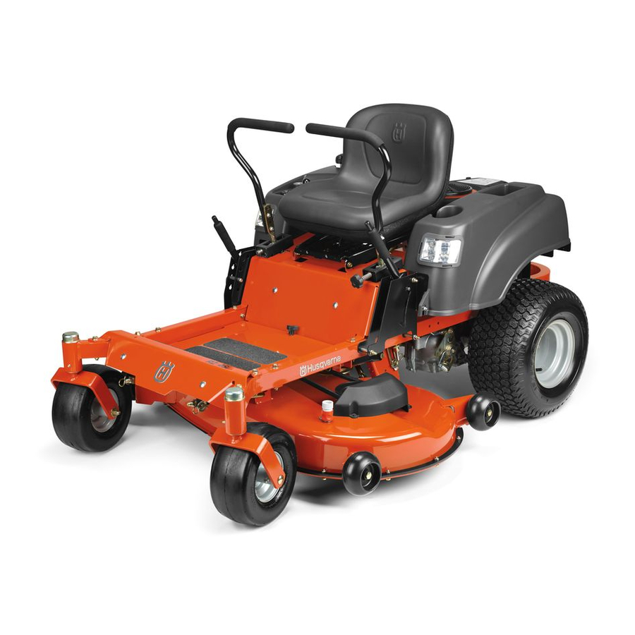
Operator Manual
Gasoline containing up to 10% ethanol (E10) is
acceptable for use in this machine. The use of any
gasoline exceeding 10% ethanol (E10) will void
the product warranty.
RZ46i / 967277602
Please read the operator manual carefully and make sure you
understand the instructions before using the machine.
Advertisement
Table of Contents

Related Manuals for Husqvarna RZ46i


Summary of Contents for Husqvarna RZ46i
- Page 1 The use of any gasoline exceeding 10% ethanol (E10) will void the product warranty. RZ46i / 967277602 Please read the operator manual carefully and make sure you understand the instructions before using the machine.
- Page 2 When this product is worn out and no longer used, it should be returned to the reseller or other party for recycling. To implement improvements, specifications and designs can be altered without prior notification. Note that no legal demands can be placed based on the information contained in these instructions. Use only original parts for repairs.
-
Page 3: Table Of Contents
CONTENTS INTRODUCTION ............... 5 Mowing Tips ............. 35 Driving and Transport on Public Roads ...... 5 Headlights ..............36 Towing ................. 5 Weak Battery ............36 Operating ..............5 Jumper Cables Use ..........36 Good Service .............. 6 Battery Voltage Light .......... 37 SYMBOLS AND DECALS .......... - Page 4 WARNING! Failure to follow cautious operating practices can result in serious injury to the operator or other persons. The owner must understand these instructions, and must allow only trained persons who understand these instructions to operate the mower. Each person operating the mower must be of sound mind and body and must not be under the influence of any mind altering substance.
-
Page 5: Introduction
INTRODUCTION Congratulations Towing Thank you for purchasing a Husqvarna ride-on If machine is equipped with a tow hitch, use extreme mower. This machine is built for superior efficiency caution when towing. Never allow children or others in to rapidly mow primarily large areas. A control panel or on the towed equipment. -
Page 6: Good Service
INTRODUCTION Good Service Husqvarna's products are sold only in specialized retail stores with complete service. This ensures that you as a customer receive only the best support and service. Before the product is delivered, the machine has, for example, been inspected and adjusted by your retailer. -
Page 7: Symbols And Decals
SYMBOLS AND DECALS These symbols are found on the machine and in the operator manual. Study them carefully so that you know what they mean. WARNING! IMPORTANT INFORMATION Xxxx xxxxxx xxxxx xxxx xxxxxxxxx Xxxx xxxxxx xxxxx xxxx xxxxxxxxx xxxxxx xxxxxx xxxxxxxxx. xx xxxxxxxx xxxx xxxxxxxxx. - Page 8 SYMBOLS AND DECALS Shut off engine before performing any Keep a safe maintenance distance from Use on slopes no Read Operator Manual or repair work the machine greater than 10° No passengers Whole body exposure Severing of fingers Do not open or remove Careful backing up, Careful going forward, to thrown objects...
-
Page 9: Safety
SAFETY Safety Instructions These instructions are for your safety. Read them carefully. WARNING! WARNING! THIS CUTTING MACHINE IS CAPABLE This symbol means that important safety OF AMPUTATING HANDS AND FEET instructions need to be emphasized. It AND THROWING OBJECTS. FAILURE concerns your safety. - Page 10 SAFETY • Disengage blades when not mowing. Shut off engine and wait for all parts to come to a complete stop before cleaning the machine, removing the grass catcher, or unclogging the discharge guard. • Operate machine only in daylight or good artificial light.
-
Page 11: Personal Safety Equipment
SAFETY Personal Safety Equipment WARNING! When using the machine, approved personal protective equipment (shown in illustrations) shall be used. Personal protective equipment cannot eliminate the risk of injury but it will reduce the degree of injury if an accident does happen. - Page 12 SAFETY • Do not try to stabilize the machine by putting a foot on the ground. • Do not mow near drop-offs, ditches, or embankments. The machine could suddenly roll over if a wheel is over the edge or if the edge caves in.
-
Page 13: Safe Handling Of Gasoline
SAFETY Safe Handling of Gasoline WARNING! The engine and the exhaust system become very hot during operation. There is risk for burns if touched. Allow engine and exhaust system to cool before refueling. To avoid personal injury or property damage, use extreme care in handling gasoline. -
Page 14: General Maintenance
SAFETY General Maintenance • Never operate machine in a closed area. • Keep all nuts and bolts tight to be sure the equipment is in safe working condition. • Never tamper with safety devices. Check their proper operation regularly. • Keep machine free of grass, leaves, or other debris buildup. - Page 15 SAFETY Sparking can occur when working with the battery and the heavy cables of the starter circuit. This can cause battery explosion, fire or eye injury. Sparking in this circuit can not occur after the chassis cable (normally negative, black) is removed from the battery. WARNING! Avoid electrical sparking and its consequences by the following routines:...
-
Page 16: Safety System
SAFETY Safety System The machine is equipped with a safety system that prevents starting or driving under the following conditions. The engine can only be started when: • The mower blades are disengaged. • The park brake is on. • The motion control levers are in neutral. -
Page 17: Transport
Code). arrester is used, it should be maintained Other states may have similar laws. Federal laws in effective working order by the apply on federal lands. operator. A spark arrestor for the muffler is available through any authorized Husqvarna dealer. -
Page 18: Controls
CONTROLS This operator manual describes the Husqvarna Zero driven hydraulic pumps. Using the left and right Turn Rider. The rider is fitted with a Briggs & Stratton steering controls, the flow is regulated and thereby the four-stroke overhead valve engine. -
Page 19: Steering Control Levers
CONTROLS Steering Control Levers The machine’s speed and direction are continuously variable using the two steering controls. The steering controls can be moved forward or backward about a neutral position. Furthermore, there is a neutral position, which is locked if the steering controls are moved outward. -
Page 20: Park Brake
CONTROLS Park Brake IMPORTANT INFORMATION The machine must be not be moving when engaging the park brake. Always set the park brake before dismounting. Release the park brake before moving the mower. The park brake is found on the left of the machine. Push the release button and pull the lever backward to activate the brake—push forward to release it. -
Page 21: Blade Switch
CONTROLS Blade Switch To engage the mower deck, pull the blade switch knob up. The mower blades are disengaged when the knob is pressed down. 8058-247 Blade switch Ignition Switch The ignition switch is placed on the control panel and is used to start and stop the engine. -
Page 22: Service Minder
CONTROLS Service Minder The service minder displays the total number of hours the engine has run and indicates when the engine and mower need servicing. After every 50 hours of operation, an oil can icon will appear and stay on for two hours, before an automatic reset occurs. -
Page 23: Fuse
CONTROLS Fuse The 20 amp primary fuse is located on the left hand side of the machine. It is accessed by tilting the seat forward. The fuse is a flat pin type used in automobiles. 8058-234 Fuse Fuel Tank Read the safety instructions before refueling. The machine has one fuel tank, just behind the console. -
Page 24: Fuel Shut Off Valve
CONTROLS Fuel Shut Off Valve The fuel shut off valve is located at the left rear of the seat. The valve is off when the handle tab is turned perpendicular to the fuel line. IMPORTANT INFORMATION Always raise the deck to the highest position for transport. -
Page 25: Operation
OPERATION Read the Safety section and following pages, if you To turn to the right are unfamiliar with the machine. While moving in a forward direction, pull the right lever back towards the neutral position while maintaining Training the position of the left lever, this will slow the rotation Due to unique steering capabilities, zero turn mowers of the right wheel and cause the machine to turn in are far more maneuverable than typical riding... -
Page 26: Smartswitch Ignition
OPERATION SmartSwitch Ignition NOTES: The default passcode [321] is preset at the factory. For safety and security, the passcode should be changed prior to use. Resetting ignition system passcode 1. To initialize the ignition system, press the START/ STOP (S/S) button on the ignition switch or sit on the seat. -
Page 27: Before Starting
OPERATION Before Starting 1. Read the sections on Safety and Controls before starting the machine. 2. Perform the daily maintenance before starting (see Maintenance Schedule in the Maintenance section). 3. Check that there is sufficient fuel in the fuel tank. 4. -
Page 28: Starting The Engine
OPERATION Starting the Engine 1. Sit on the seat. 2. Raise the mower deck by pushing the release button on the top of the lifting lever. Pull the lifting lever backward to the locked (transport) position. 8058-019 Mower deck lifting lever 3. - Page 29 OPERATION 5. Move the steering controls outward to the locked (outer) neutral position. 8058-190 Place controls in neutral position 6. Move the throttle lever to the full throttle position. NOTE: There is a detent at the full throttle position to aid in setting the control. F, move the If the temperature is below 32 throttle lever up to the cold weather (snowflake)
- Page 30 OPERATION 7. Press and release the S/S button to activate the ignition switch. Check that the indicator is blinking blue. IMPORTANT INFORMATION Either of two actions will wake up the ignition switch—either the operator sitting on the seat or pressing the S/S button. Enter the passcode and press the S/S button.
-
Page 31: Ignition System Faults
OPERATION Ignition System Faults The SmartSwitch Ignition is programmed to warn when any part of the safety system is not being followed and will not allow the unit to be started until all system faults are resolved. The park brake fault light will blink if the park brake has not been engaged. -
Page 32: Running
OPERATION Running 1. Release the park brake by pushing the top release button in and moving the lever downward. NOTE: The mower is equipped with an operator presence system. When the engine is running, any attempt by the operator to leave the seat without first setting the park brake will shut off the engine. -
Page 33: Stopping The Engine
OPERATION Stopping the Engine 1. Move the throttle to the mid throttle position. 2. Move the steering controls outward. 3. Disengage the mower deck by pressing the blade switch down. 8058-249 Disengage the mower deck and move throttle to minimum 4. -
Page 34: Operating On Hills
OPERATION Operating On Hills Read the safety instructions Driving on Slopes in the Safety section. WARNING! Do not drive up or down hills with slopes greater than 10 degrees. Do not drive across slopes. • The slowest speed possible should be used before starting up or down hills. -
Page 35: Mowing Tips
OPERATION Mowing Tips WARNING! • Observe and flag rocks and other fixed objects to Clear the lawn of stones and other avoid collisions. objects that can be thrown out by the • Begin with a high cutting height and reduce it blades. -
Page 36: Headlights
OPERATION Headlights Use Button 2 to turn on/off the headlights. When the engine is in start mode, press the button to turn the headlights on. A blinking Button 2 light signals that one or both headlights are not working. The headlights can also be used when the ignition switch is not activated or the unit is not running. -
Page 37: Battery Voltage Light
OPERATION Battery Voltage Light A battery voltage light can indicate that voltage is below the normal operating power. If the battery is low when a start attempt is made, the battery indicator button will light up. This is an indication the battery should be charged. It will not prevent additional start attempts as long as remaining charge is capable of cranking the engine. -
Page 38: Maintenance
MAINTENANCE Maintenance Schedule The following is a list of maintenance procedures that an authorized service workshop is recommended to must be performed on the machine. For those points maintain your machine in the best possible condition not described in this manual, visit an authorized and to ensure safe operation. - Page 39 MAINTENANCE At least Maintenance interval Daily once in hours each MAINTENANCE Before After year ■ Check/adjust throttle cable ● ● Check the condition of belts, belt pulleys ■ ■ Change the engine oil ■ ■ Replace the engine oil filter ■...
-
Page 40: Battery
MAINTENANCE Battery STANDARD STATE APPROXIMATE BATTERY CHARGING TIME* TO FULL CHARGE AT 80 F / 27 Your mower is equipped with a maintenance free BATTERY Maximum Rate at: battery and does not need servicing. However, CHARGE 50 Amps 30 Amps 20 Amps 10 Amps periodic charging of the battery with an automotive... -
Page 41: Safety System
Visually check that no damage is found on the lever, links or switch belonging to the park brake. Perform a standstill test and check that there is sufficient braking action. To adjust the park brake, contact the Husqvarna service workshop. IMPORTANT INFORMATION The machine must be absolutely standing still when applying the park brake. -
Page 42: Tire Pressures
MAINTENANCE Tire Pressures All tires should be at 15 psi / 103 kPa / 1 bar. IMPORTANT INFORMATION DO NOT add any type of tire liner or foam fill material to the tires. Excessive loads created by foam filled tires will cause premature failures. Only use O.E.M. -
Page 43: V-Belts
MAINTENANCE V-belts Check every 100 hours of operation. Check for severe cracking and large nicks. NOTE: The belt will show some small cracks in normal operation. The belts are not adjustable. Replace belts if they begin to slip from wear. Deck Belt Removal 1. -
Page 44: Cutting Blades
5. Torque blade bolt to 45-55 ft/lbs (60-75 Nm). IMPORTANT INFORMATION Special blade bolt is heat treated. 8058-129 Blade Replace with a Husqvarna bolt if required. Blade bolt (special) Do not use lower grade hardware than Spindle housing specified. Blade attachment... -
Page 45: Adjusting The Mower Deck
MAINTENANCE Adjusting the Mower Deck Leveling deck Adjust the deck while the mower is on a level surface. Make sure the tires are inflated to the correct pressure. See Technical Data / Transmission. If tires are under or over inflated, the deck cannot be properly adjusted. -
Page 46: Cleaning
MAINTENANCE Cleaning IMPORTANT INFORMATION Regular cleaning, especially under the mower deck, Use protective glasses when will increase the machine’s life-span. Make it a habit cleaning and washing. to clean the machine directly after use (after it is cooled), before the debris sticks. Do not spray water on the top of the mower deck. -
Page 47: Lubrication
LUBRICATION Lubrication Schedule 12/12 Every year Lubricate with grease gun Filter change 1/52 Every Week 1/365 Every day Oil change Level check General Wipe away excess grease after lubrication. When lubricating with an oil can, it must be filled with engine oil. -
Page 48: Wheel And Deck Zerks
Transmission The transmission is maintenance free with no need for level checks or oil changes. If a leak occurs, replace the unit or contact your Husqvarna dealer. Deck Spindles Lower the cutting deck completely. If a grease gun without rubber hose is used, the foot plate must be removed. -
Page 49: Troubleshooting
TROUBLESHOOTING Problem Cause Engine will not start • Blade switch is engaged. • Steering controls are not locked in the neutral position • Park brake is not activated • Battery is dead • Contamination in the carburetor or fuel line. •... - Page 50 TROUBLESHOOTING Problem Cause Engine overheats • Clogged air intake or cooling fins • Engine overloaded • Poor ventilation around engine • Defective engine speed regulator • Too little or no oil in the engine • Contamination in the carburetor or fuel line. •...
-
Page 51: Storage
Drain the fuel into an approved container outdoors and store Always use genuine Husqvarna spare parts. far away from open flame. Never use An annual check-up at an authorized service gasoline for cleaning. Use a degreaser workshop is a good way to ensure that your machine and warm water instead. -
Page 52: Schematics
SCHEMATIC... -
Page 53: Technical Data
TECHNICAL DATA Torque Specifications Engine crankshaft bolt 75 ft/lb (100 Nm) Standard ¼" fasteners 9 ft/lb (12 Nm) Deck pulley bolts 75 ft/lb (100 Nm) Standard " fasteners 18 ft/lb (25 Nm) Lug nuts 75 ft/lb (100 Nm) Standard " fasteners 33 ft/lb (44 Nm) Blade bolt 55 ft/lb (75 Nm) - Page 54 TECHNICAL DATA Engine The power rating as declared by the engine manufacturer is the average gross Manufacturer Briggs & Stratton power output at the specified RPM of a Type Endurance typical production engine for the engine model measured using SAE Standards for Power 23 hp 1,2)
-
Page 55: Conformity Certificates
CONFORMITY CERTIFICATES USA requirements Labels are placed on the engine and/or in the engine compartment stating that the machine will fulfill the requirements. This is also applicable to special requirements for any of the states, (California emission rules etc.). Do not remove any of these labels. Certificates can also be supplied with the machine at delivery or written in the Engine manual. -
Page 56: Service Journal
SERVICE JOURNAL Date, mtr reading, stamp, sign Action Delivery Service Charge the battery Adjust the tire pressure of all wheels to 15 PSI (1 bar) Mount the steering controls in the normal position Connect the contact box to the cable for the seat’s safety switch Check that the right amount of oil is in the engine Adjust the position of the steering controls Fill with fuel and open the fuel shut off valve... - Page 57 SERVICE JOURNAL Date, mtr reading, stamp, sign Action After the First 10 Hours Change engine oil Action Date, mtr reading, stamp, sign 25-Hour Service Check the fuel pump’s air filter Sharpen/Replace mower blades if required Check the tire pressures Check battery with cables Lubricate according to lubrication chart Check/clean the engine’s cooling air intake Clean the air cleaner’s foam pre-filter...
- Page 58 SERVICE JOURNAL Date, mtr reading, stamp, sign Action 50-Hour Service Perform the 25-hour service Clean/replace the air cleaner’s paper filter cartridge (shorter intervals for dusty operating conditions) Change engine oil Lubricate according to lubrication chart Check/adjust the park brake Date, mtr reading, stamp, sign Action 100-Hour Service Perform the 25-hour service...
- Page 59 SERVICE JOURNAL Date, mtr reading, stamp, sign Action 300-Hour Service Perform the 25-hour service Perform the 50-hour service Perform the 100-hour service Check/adjust the mower deck Clean the combustion chamber and grind the valve seats Check the engine valve clearance Replace the air cleaner’s foam pre-filter Action Date, mtr reading, stamp, sign...
- Page 60 SERVICE JOURNAL Date, mtr reading, stamp, sign Action...
- Page 61 SERVICE JOURNAL Date, mtr reading, stamp, sign Action...
- Page 62 SERVICE JOURNAL Date, mtr reading, stamp, sign Action...
- Page 64 115 646927 Rev A 2013-10-15...