Table of Contents
Advertisement
Advertisement
Table of Contents

Related Manuals for Foxconn Destroyer


Summary of Contents for Foxconn Destroyer
- Page 1 Destroyer Motherboard User’s Manual...
- Page 2 Statement: This manual is the intellectual property of Foxconn, Inc. Although the information in this manual may be changed or modified at any time, Foxconn does not obligate itself to inform the user of these changes. Trademark: All trademarks are the property of their respective owners.
-
Page 3: Declaration Of Conformity
HON HAI PRECISION INDUSTRY COMPANY LTD 66 , CHUNG SHAN RD., TU-CHENG INDUSTRIAL DISTRICT, TAIPEI HSIEN, TAIWAN, R.O.C. declares that the product Motherboard Destroyer is in conformity with (reference to the specification under which conformity is declared in accordance with 89/336 EEC-EMC Directive) ■... - Page 4 Declaration of conformity Trade Name: FOXCONN Model Name: Destroyer Responsible Party: PCE Industry Inc. Address: 458 E. Lambert Rd. Fullerton, CA 92835 Telephone: 714-738-8868 Facsimile: 714-738-8838 Equipment Classification: FCC Class B Subassembly Type of Product: Motherboard Manufacturer: HON HAI PRECISION INDUSTRY...
-
Page 5: Installation Precautions
Installation Precautions ■ Electrostatic discharge (ESD) is the sudden and momentary electric current that flows between two objects at different electrical potentials. Normally it comes out as a spark which will quickly damage your electronic equipment. Please wear an electrostatic discharge (ESD) wrist strap when handling components such as a motherboard, CPU or memory. -
Page 6: Table Of Contents
TABLE OF CONTENTS Chapter 1 Product Introduction Package List .....................2 Product Specifications ................3 Layout.......................5 Back Panel Connectors ................6 Chapter 2 Hardware Install Install the CPU and CPU Cooler ..............9 Install the Memory .................. 11 Install an Expansion Card ..............13 Install other Internal Connectors ............14 Install the Optional Accessory ..............18 Jumpers ....................19 Onboard Button ..................21... - Page 7 CONFIG ...................55 FOX LiveUpdate Local Update ..................56 Online Update ..................58 Configure ..................61 About & Help ..................63 FOX DMI ....................64 FOX LOGO .....................65 Chapter 5 RAID Configuration RAID Configuration Introduction.............68 NVIDIA® MediaShield Driver ..............70 Create RAID Driver Diskette ..............72 RAID Enable in BIOS ................74 Select a RAID Array for Use ..............74 Install a New Windows XP ..............90 Setting Up a Non-Bootable RAID Array..........97...
- Page 8 Thank you for buying Foxconn Quantum Force series motherboard- Destroyer. Foxconn Quantum Force products are engineered to maximize computing power, providing only what you need for break- through performance. With advanced overclocking capability and a range of connectivity features for today multi-media computing requirements, Destroyer enables you to unleash more power from your computer.
-
Page 9: Package List
Package List Check your product package for the following items: Motherboard Foxconn Destroyer motherboard 1 x USB 2.0 x 2 ports and 1 x 1394a module I/O modules 1 x SPDIF Out module 4 x SATA power and signal cables... -
Page 10: Product Specifications
1-1 Product Specifications Support AMD socket AM2+ Phenom FX / Phenom series processors Support AMD socket AM2 series processors : 64 FX / Athlon 64X2 Dual-Core / Athlon Athlon X2 Dual-Core / 64 / Sempron Athlon HyperTransport 2000/1600MT/s for AM2 CPU Up to 5200MT/s (HT3.0) for AM2+ CPU Chipset NVIDIA nForce 780a SLI... - Page 11 1 x COM1 connector 1 x IrDA connector 1 x Chassis intrusion alarm header (INTR) 1 x S/PDIF Out connector 1 x 1394a connector Back Panel 1 x PS/2 keyboard port Connectors 1 x VGA port 1 x DVI-D port 1 x 1394a port 2 x External SATA ports (Controlled by JMicron JMB362) 6 x USB 2.0 ports...
-
Page 12: Layout
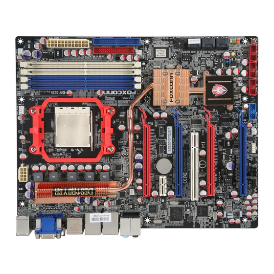
1-2 Layout 14 15 1. 8-pin ATX 12V Power Connector 17. SATA Connectors 2. SYS_FAN Headers 18. Speaker Connector 3. PCI Express x1 Slot 19. BIOS_SELECT Jumper 4. PCI Slot 20. IrDA Connector 5. PCI Express x16 Slots 21. Chipset: NVIDIA nForce 780a SLI 6. -
Page 13: Back Panel Connectors
1-3 Back Panel Connectors 1394a Port LAN Ports PS/2 Keyboard Port VGA Port Line Out Line In Rear Speaker Subwoofer Side Speaker Microphone USB Ports DVI-D Port External SATA USB Ports Audio Ports Ports 1. PS/2 Keyboard Port Use the upper port (Purple) to connect a PS/2 keyboard. 2. - Page 14 8. RJ-45 LAN Ports The Ethernet LAN port provides Internet connection at up to 10/100/1000Mb/s data rate. Left: Active Right: Link Active Link LAN Type Status Description Status Description No Link No Link 10Mb/s Connection 1000M Green Data Green 100Mb/s Connection Blinking Activity Orange...
- Page 15 This chapter introduces the hardware installation process, including the installation of the CPU, memory, power supply, slots, pin headers and the mounting of jumpers. Caution should be exercised during the installation of these modules. Please refer to the motherboard layout prior to any installation and read the contents in this chapter carefully.
-
Page 16: Install The Cpu And Cpu Cooler
2-1 Install the CPU and CPU Cooler Read the following guidelines before you begin to install the CPU : ■ Make sure that the motherboard supports the CPU. ■ Always turn off the computer and unplug the power cord from the power supply before installing the CPU to prevent hardware damage. -
Page 17: Install The Cpu Cooler
Install the CPU Cooler Follow the steps below to correctly install the CPU cooler. (The following procedures use Foxconn cooler as the example.) 2. Buckle the heatsink firmly at one 1. Apply and spread an even thermal side of the stand. -
Page 18: Install The Memory
2-2 Install the Memory Read the following guidelines before you begin to install the memory : ■ Make sure that the motherboard supports the memory. It is recommended that memory of the same capacity, brand, speed, and chips be used. ■... -
Page 19: Installing A Memory
Installing a Memory Before installing a memory module, make sure to turn off the computer and unplug the power cord from the power outlet to prevent damage to the memory module. Be sure to install DDR2 DIMMs on this motherboard. Notch If you take a look at front side of memory module, it has asymmetric pin counts on both sides separated by a notch in the middle, so it can only fit in one direction. -
Page 20: Install An Expansion Card
2-3 Install an Expansion Card ■ Make sure the motherboard supports the expansion card. Carefully read the manual that came with your expansion card. ■ Always turn off the computer and unplug the power cord from the power outlet before installing an expansion card to prevent hardware damage. -
Page 21: Install Other Internal Connectors
2-4 Install other Internal Connectors Power Connectors This motherboard uses an ATX power supply. In order not to damage any device, make sure all the devices have been installed properly before applying the power supply. 24-pin ATX power connector : PWR1 PWR1 is the ATX power supply connector. - Page 22 Connect a 4-pin power plug We recommend you using an 8-pin ATX 12V power supply. If you are using a 4-pin power supply, you need to align the ATX power connector according to the picture on the right. Front Panel Connector : FP1 This motherboard includes one connector for connecting the HDD-LED PWR-LED...
- Page 23 COM Connector : COM1 This motherboard supports one serial RS232 COM port RLSD SOUT for legacy compatibility. User must purchase another RS232 cable with a 9-pin D-sub connector at one end to connect with the external RS232 device and another EMPTY end with 10-pin female connector to connect with COM1 connector in the motherboard.
- Page 24 Audio Connector : F_AUDIO PORT1_L AUD_GND The audio connector supports HD Audio standard. PORT1_R PRESENCE_J It provides the Front Audio output choice. PORT2_R SENSE1_RETURN SENSE_SEND EMPTY SENSE2_RETURN PORT2_L Audio Connector : CD_IN F_AUDIO CD_IN is a Sony standard audio connector, it can be connected to a CD/DVD-ROM drive through a CD/DVD CD_L GND CD_R audio cable.
-
Page 25: Install The Optional Accessory
2-5 Install the Optional Accessory Install Heat-Pipe Expansion Module 1. Find the chipset heatsink, take off the removable piece in its groove. 2. Find the Heat-Pipe expansion module, remove the protected film from its surface. 3. Place the Heat-pipe onto the heatsink, and fasten four screws to fix it. Screw Screw Install Quantum Flow-GPU Blower... -
Page 26: Jumpers
2-6 Jumpers For some features needed, users can change the jumper settings on this motherboard to modify them. This section explains how to use the various functions of this motherboard by changing the jumper settings. Users should read the following content carefully prior to modifying any jumper setting. Description of Jumpers 1. - Page 27 BIOS Select Jumper: BIOS_SELECT This motherboard provides two BIOS ROMs, and user can easily select one of them for operation. The selection of BIOS ROM can be done by hardware jumper fix or by software BIOS configuration. The jumper is used to select the booting from BIOS ROM 1 or BIOS ROM 2.
-
Page 28: Onboard Button
2-7 Onboard Button Power on Button: POWER_ON Push the power on button to power on the system. Reset Button: RESET Push the reset button to reboot the system. Clear CMOS Button: CLR_CMOS1 Turn off the AC power supply, push the CLR_CMOS1 button and hold there for a couple of seconds to clear CMOS. - Page 29 This chapter tells how to change system settings through the BIOS Setup menus. Detailed descriptions of the BIOS parameters are also provided. You have to run the Setup Program when the following cases oc- cur: 1. An error message appears on the screen during the system Power On Self Test (POST) process.
-
Page 30: Enter Bios Setup
Enter BIOS Setup The BIOS is the communication bridge between hardware and software, correctly setting up the BIOS parameters is critical to maintain optimal system performance. Power on the computer, when the message "Press TAB to show POST screen, DEL to enter SETUP" appears at the bottom of the screen, you can press <Del>... - Page 31 ► PC Health Status This setup enables you to read/change Fan speeds, and displays temperatures and voltages of your CPU/System. ► Quantum BIOS Some special proprietary features (such as overclocking) can be set up through this menu. ► Load Optimized Defaults The optimal performance settings can be loaded through this menu.
-
Page 32: System Information
[ None] ► ESATA Channel 2 Master [ None] [1.44M, 3.5 in.] Drive A Halt On [All , But Keyboard] Model Name: Destroyer BIOS Version: 1024M Memory: BCM5788 MAC Address 00 1C 25 3B CC AF ↑↓→←:Move Enter:Select +/-/PU/PD:Value F10:Save... - Page 33 ► SATA Channel 1/2/3/4 Master / ESATA channel 1/2 Master When SATA Operation Mode is set to [IDE], These items will appear. The relationships between SATA channels and SATA ports on the motherboard are : SATA Channel 1 Master is the lower SATA port of SATA_1 on the motherboard. SATA Channel 2 Master is the lower SATA port of SATA_2 on the motherboard.
-
Page 34: Advanced Bios Features
Advanced BIOS Features Phoenix - AwardBIOS CMOS Setup Utility Advanced BIOS Features ► Removable Device Priority [Press Enter] Item Help Press Enter ► Hard Disk Boot Priority [Press Enter] ► CD-ROM Boot Priority Menu Level ► [Press Enter] First Boot Device [Hard Disk] Second Boot Device [CDROM]... -
Page 35: Advanced Chipset Features
Advanced Chipset Features Phoenix - AwardBIOS CMOS Setup Utility Advanced Chipset Features x Hybrid SLI Disabled Item Help x Display Detection Enabled Menu Level ► iGPU Frame Buffer Control [Auto] Auto x Frame Buffer Size OnBoard GPU [Enable If NO Ext GPU] Init Display First [PCIEx] ↑↓→←:Move Enter:Select... - Page 36 initialization. This fixed amount of memory will provide the user with a guaranteed graphics memory at all times, and will no longer be available to the OS. ► OnBoard GPU This item is used to set whether to enable the onboard GPU (Graphic Processor Unit) in the North Bridge.
-
Page 37: Integrated Peripherals
Integrated Peripherals Phoenix - AwardBIOS CMOS Setup Utility Integrated Peripherals ► OnChip IDE Devices [Press Enter] Press Enter Item Help ► MCP SATA Mode [Press Enter] ► OnBoard Devices Menu Level ► [Press Enter] ► SuperIO Devices [Press Enter] ► USB Devices [Press Enter] ↑↓→←:Move Enter:Select +/-/PU/PD:Value F10:Save... - Page 38 MCP SATA Mode Phoenix - AwardBIOS CMOS Setup Utility MCP SATA Mode SATA Operation Mode [IDE] Item Help x SATA Pri-Master RAID Disabled Menu Level ► x SATA Pri-Slave RAID Disabled x SATA Sec-Master RAID Disabled x SATA Sec-Slave RAID Disabled x SATA Thi-Master RAID Disabled...
-
Page 39: Onboard Devices
► SATA Pri-Master RAID / SATA Pri-Slave RAID / SATA Sec-Master RAID / SATA Sec-Slave RAID / SATA Thr-Master RAID / SATA Thr-Slave RAID These items are valid only when "SATA Operation Mode" is set to RAID. They are used to en- able or disable the RAID function of each SATA port on the motherboard. - Page 40 ► OnBoard BCM5788 / BCM5786 Controller This item is used to enable or disable the onboard LAN controller. ► OnBoard 1394 Controller This item is used to enable or disable the onboard 1394 controller. ► BCM5788 / BCM5786 LAN Boot ROM This item is used to enable or disable the onboard LAN boot optional ROM.
- Page 41 USB Devices Phoenix - AwardBIOS CMOS Setup Utility USB Devices USB 1.1 Controller Enabled Item Help USB 2.0 Controller [Enabled] Menu Level ► USB Operation Mode [High Speed] USB Keyboard Support [Enabled] [Enable] or [Disable] USB Mouse Support [Enabled] Open Host Controller USB Storage Support [Enabled] Interface for Universal...
-
Page 42: Power Management Setup
Power Management Setup Phoenix - AwardBIOS CMOS Setup Utility Power Management Setup ACPI Function [Enabled] Enabled Item Help ACPI Suspend Type [S3(STR)] Menu Level ► Power Button [Instant-Off] PWRON After PWR-Fail [Off] HPET Support [Enabled] ** Power Management Events ** Resume by PCI/PCIE PME [Disabled] USB KB/MS Resume from S3... - Page 43 ► ACPI Function This item is used to enable or disable the ACPI function. ► ACPI Suspend Type This item is used to set the energy saving mode of the ACPI function. When you select “S1 (POS)” mode, the power is always on and computer can be resumed at any time. When you select “S3 (STR)”...
- Page 44 ► KB Resume Password Wen "PS/2 KB Resume from S3" is set to [Password], this item allows you to input a password to wake up the system from S3 mode. ► Hot Key Resume Wen "PS/2 KB Resume from S3" is set to [Hot KEY], this item allows you to press a [Ctrl] + Function key to wake up the system from S3 mode.
-
Page 45: Pc Health Status
PC Health Status Phoenix - AwardBIOS CMOS Setup Utility PC Health Status Case Open Warning [Disabled] Item Help Disabled Shutdown Temperature [Disabled] Menu Level ► CPU Vcore 1.36V + 5V 5.08V + 3.3V 3.23V +12V 12.37V DDR2(V) 1.80V 5VSB(V) 5.14V Voltage of Battery 3.05V CPU Temperature... -
Page 46: Quantum Bios
Quantum BIOS Phoenix - AwardBIOS CMOS Setup Utility Quantum BIOS ► CPU Feature Press Enter [Press Enter] Item Help ► Memory Timing Setting [Press Enter] ► All Voltage Control Menu Level ► [Press Enter] ► OC Gear [Press Enter] Over Clock Phase Select [O.C. -
Page 47: Cpu Feature
This option is used to enable or disable clock generator spread spectrum. If you enabled this func- tion, it can significantly reduce the EMI (Electromagnetic Interference) generated by the system, so to comply with FCC regulation. But if overclocking is activated, you had better disable it. ►... -
Page 48: Memory Timing Setting
At this moment, AMD family 10 series is equivalent to AM2+, and most CPU in this series are Quad Cores. This option enables shutting down portions of the circuits in core when not in load, it is a new feature of AM2+ CPU. This option will be displayed only if your CPU is supporting this feature. - Page 49 new capabilities and prompt the user to set PC boot parameters for guaranteed optimized settings. AM2+ CPU - Select [Disabled] to turn off SLI-Memory feature. Select [CPUOC 0%] to enable using SLI-Memory SPD data to run your system. If overclock is needed, you have to adjust memory or CPU clocks from other BIOS options to overclock your system manually.
- Page 50 rameters, so that the motherboard memory controller (chipset) can better access the memory. This item can be valid only when the “Over Clock Phase Select” is set to [Manual O.C.]. The following items can be valid only when the “DRAM Timing Selectable” is set to [Manual]. ►...
- Page 51 All Voltage Control Phoenix - AwardBIOS CMOS Setup Utility All Voltage Control x CPU Target Voltage 1.3500V Item Help CPU Current Voltage 1.2960V 1.3500V Menu Level ► CPU Default Voltage x CPU HT Voltage Setting 1.2000V x DRAM Voltage Multiplier Default x DRAM Voltage Setting 1.8267V...
- Page 52 Restore My Setting Restore x Clear My Setting Clear Choose storage section 1 or 2 or 3 or 4 to ********** Foxconn Function ********** store your over clock Super BIOS Protect [Disabled] setting. If you store Smart Boot Menu...
-
Page 53: Load Optimized Defaults
Load Optimized Defaults Select this option and press <Enter>. A dialogue pops out, select <Y> then press <Enter> to load the defaults; press <N> to skip. Load Optimized Defaults (Y/N)? N By this default, BIOS have set the optimized performance parameters of system to improve the performances of system components. -
Page 54: Utility Cd Content
The utility CD that came with the motherboard contains useful software and several utility drivers that enhance the motherboard features. This chapter includes the following information: ■ Utility CD content ■ Install driver and utility ■ FOX ONE ■ FOX LiveUpdate ■... -
Page 55: Utility Cd Introduction
Utility CD introduction This motherboard comes with a Utility CD. To begin with, simply insert the CD into your DVD-ROM. The CD will automatically run and display the main menu on the screen. 1. Install Driver Click on "Install Driver", then use these options to install all the necessary drivers for your motherboard. - Page 56 Use these options to install additional software programs. AEGIS PANEL Foxconn new utility software for monitoring system information. See “AEGIS PANEL” for details. FOX LiveUpdate The Fox LiveUpdate allows you to backup or update the system BIOS, drivers and utilities in Windows ®...
- Page 57 For the usage of the created RAID driver floppy, please go to Chapter 5, "5-4 Creating a Bootable Array-Install a New Windows XP" for more detail. 4. Foxconn Website Click it to visit Foxconn’s Website. 5. Browse CD Click it to browse the CD content.
-
Page 58: Aegis Panel
AEGIS PANEL This is Foxconn’s new utility software. Aegis Panel is a Windows innovation tool to provide fan control, alarm function and system monitoring information such as fan speed, temperature, voltage and CPU clock etc.. The powerful features are: Overclocking (OC) HWM INFO. -
Page 59: Overclocking
Open Aegis Panel and directly enter configure mode. Exit : Close Aegis program. 2. Overclocking Click on "Foxconn" button to open/close the display screen. The information of CPU, memory, and PCIE clocks are displayed. Open/Close screen Click on Control Panel button, and its panel appears. Then click on OC button to visit Overclocking menu which allows you to overclock your CPU and PCIE bus manually. -
Page 60: Hwm Info
3. HWM INFO. (Hardware Monitor Information) Click on "HWM INFO." button to display the fan's information. In this fan control panel, you can configure five different fan's speeds. Fan icon HWM INFO button Fan Operations The Smart CPU Fan Feature only works with a cooler which accompanies 4-wire cable. Click on fan icon to configure each fan's function. -
Page 61: Alarm
Slope PWM Value: To define the slope of PWM when the tem- perature changes. The higher the slope is, the faster the fan speed changes. FAN1 and FAN2 only copy their working models from one of CPU FAN, SYS_FAN1 and SYS_FAN2, and they do not own their detailed settings. -
Page 62: Config
5. CONFIG Go to System Tray CONFIG button Click "CONFIG" button to configure Aegis function. (Recommend using default values if possible). Fahrenheit / Celsius scales : You can select temperature scales between them. External / OnBoard Speaker : It allows you to choose the warning tone devices. Refresh Interval : It is used to select the interval of refreshing the current monitoring information such as the CPU clock, temperature, voltage etc.. -
Page 63: Fox Liveupdate
FOX LiveUpdate FOX LiveUpdate is a useful utility to backup and update your system BIOS, drivers and utilities by local or online. Supporting Operating Systems : ■ Windows 2000 ■ Windows XP (32-bit and 64-bit) ■ Windows 2003 (32-bit and 64-bit) ■... - Page 64 1-2 Local Update - Backup This page can backup your system BIOS. You can click “Backup”, and key in a file name, then click “Save” to finish the backup operation. The extension of this backup file is ".BIN" for Award BIOS and ".ROM"...
-
Page 65: Online Update
2. Online Update 2-1 Online Update - Update BIOS This page lets you update your system BIOS from Internet. Click “start”, it will search the new BIOS from Internet. Then follow the wizard to finish the update operation. Click here Current information Search new BIOS from Internet... - Page 66 Select the driver to update Browse detailed information Install the selected driver Close the window 2-3 Online Update - Update Utility This page lets you update utilities from Internet. Click “start”, it will search the new utilities from Internet. Then follow the wizard to finish the update operation. Click here Current information Search new utilities...
- Page 67 2-4 Online Update - Update All This page lets you update your system drivers from Internet. Click “start”, it will search all new BIOS/drivers/utilities from Internet. Then follow the wizard to finish the update operation. Click here Current information Search all new BIOS/ drivers/utilities from Internet Browse detailed...
-
Page 68: Configure
3. Configure 3-1 Configure - option This page lets you set auto search options. After you enable the auto search function, FOX LiveUpdate will start its searching from Internet and if any qualified item found, it will pop out a message on the task bar to inform you to do the next step. - Page 69 When you enable "Auto Search FOX LiveUpdate", if your FOX LiveUpdate version is older, it will auto search from internet and prompt you to install the new version. Prompt you to install the new FOX LiveUpdate 3-2 Configure - System This page lets you set the backup BIOS location and change different skin of the FOX LiveUpdate utility.
-
Page 70: About & Help
3-3 Configure - Advance This page lets you select to flash BIOS / Boot Block and clear CMOS. If you choose Flash Boot Block, it means BIOS is not protective, and you must make sure the flash process is continuous and without any interruption. -
Page 71: Fox Dmi
FOX DMI FOX DMI is a full Desktop Management Interface viewer, and it provides three DMI data formats : Report, Data Fields and Memory Dump. With DMI information, system maker can easily analyze and troubleshoot your mother- board if there is any problem occurred. Supporting Operating Systems : ■... -
Page 72: Fox Logo
FOX LOGO FOX LOGO is a simple and useful utility to backup, change and delete the boot time Logo. The boot Logo is the image that appears on screen during POST (Power-On Self-Test). You can prepare a JPG image (1024x768) file, then use FOX LOGO to open it and change the boot time Logo. - Page 73 This chapter will cover two topics : ■ Creating a Bootable Array - Installing a new Windows XP (Vista) in a brand new RAID system. ■ Creating a Non-Bootable Array - Existing Windows XP (Vista) system with new RAID built as data storage. It includes the following information : ■...
-
Page 74: Creating A Non-Bootable Array - Existing Windows Xp (Or Vista)
Creating a Bootable Array - Installing a new Windows XP (or Vista) in a brand new RAID system. 1. Follow 5-1 to create RAID driver diskette. 2. Follow 5-2 to set RAID enabled in BIOS. 3. Follow 5-3 to select a RAID array for use. 4. -
Page 75: Raid Configuration Introduction
RAID Configuration Introduction RAID (Redundant Array of Independent Disks) is a method for computer data storage schemes that divide and/or replicate data among multiple hard drives. RAID can be designed to provide increased data reliability (fault tolerance) or increased I/O (input/ output) performance, or both. - Page 76 RAID 0 (Striped) RAID 0 reads and writes sectors of data interleaved among multiple drives. If any disk member fails, it affects the entire array. The disk array data capacity is equal to the number of drive members times the capacity of the smallest member. RAID 0 does not support fault tolerance.
-
Page 77: Nvidia® Mediashield Driver
MediaShield Driver ® NVIDIA MediaShield driver supports RAID 0, RAID 1, RAID 5, and RAID 0+1 ® The NVIDIA functions. It allows you to get high performance with fault tolerance, big capacity, or data safety provided by different RAID functions. Here, we will use four SATA hard disks as an example to guide you how to select your RAID system. - Page 78 Port 0.3 is the upper SATA port of SATA_2. Port 0.4 is the lower SATA port of SATA_3. Port 0.5 is the upper SATA port of SATA_3. MediaShield BIOS Mar 31 2008 - Define a New Array - Optimal RAID Mode: Mirrored Striped Stripe Block: Optimal...
-
Page 79: Create Raid Driver Diskette
5-1 Create RAID Driver Diskette If you want to install a brand new Windows XP on a RAID system, you need to create two RAID driver floppy diskettes which will be used during Windows XP installation later. 1. Find a PC, put a diskette into its floppy drive A:, put the driver CD into DVD-ROM drive. - Page 80 6. Go to CD:\Driver\Chipset\xp\IDE\ WinXP\sataraid\floppy\Disk2, coppy all the content to the second diskette. Repeat the steps from step 1 to step 5. Later, when in the process of installing Windows XP in your RAID system, it will ask you to use these floppy diskettes to provide driver for additional specific devices, for example, a RAID device.
-
Page 81: Raid Enable In Bios
5-2 RAID enable in bIos 1. Enter the BIOS setup by pressing [DEL] key when boot up. 2. Select the “Integrated Peripherals” from the “Main menu”, then select the “MCP SATA Mode” menu and press [Enter] to go to the configuration items. 3. -
Page 82: Create Raid 0 (Striped)
Create RAID 0 (striped) 1. Select "striped" from the RAID Mode. The menu appears : MediaShield BIOS Mar 31 2008 - Define a New Array - Optimal RAID Mode: Mirrored Striped Stripe Block: Optimal Free Disks Array Disks Port Disk Model Capacity Port Disk Model Capacity... - Page 83 4. The stripe value should be selected based on different applications. It ranges from 4KB to 128KB. Some suggested choices are : 16K - Best for sequential transfer. 64K - Good general purpose strip size. 128K - Best performance for most desktops and workstations. Keep it at Optimal default value.
- Page 84 6. The screen displays a STRIPE array of 153.38GB, which is twice the size of the smallest hard disk. That is, 2*76.69GB = 153.38GB. If you want to build a new Operating System (such as Windows XP) in this RAID system, please press [B] to select it as bootable.
-
Page 85: Create Raid 1 (Mirrored)
Create RAID 1 (Mirrored) 1. Select “Mirrored” from the RAID Mode. MediaShield BIOS Mar 31 2008 - Define a New Array - Optimal RAID Mode: Mirrored Stripe Block: Optimal Mirrored Free Disks Array Disks Port Disk Model Capacity Port Disk Model Capacity 0.0 WDC WD1200JD-9 111.79GB 0.0 WDC WD1200JD-9 111.79GB... - Page 86 4. The stripe block value is fixed and not changeable. Press [F7] to finish the setting. MediaShield BIOS Mar 31 2008 - Define a New Array - Optimal RAID Mode: Mirrored Mirrored Stripe Block: Optimal Free Disks Array Disks Port Disk Model Capacity Port Disk Model Capacity...
- Page 87 6. The screen displays a MIRRORED array of 232.88GB, which is the size of the smallest hard disk. That is, 232.88GB. If you want to build a new Operating System (such as Windows XP) in this RAID system, please press [B] to select it as bootable. You can then press [Ctrl]+[X] keys to exit the setup program, and restart your PC.
- Page 88 Create RAID 0+1 (striped Mirror) 1. Select “striped Mirror” from the RAID Mode. The menu appears : MediaShield BIOS Mar 31 2008 - Define a New Array - Optimal RAID Mode: Mirrored Stripe Block: Optimal Striped Mirror Free Disks Array Disks Port Disk Model Capacity Port Disk Model...
- Page 89 4. The stripe value should be selected based on different applications. It ranges from 4KB to 128KB. Some suggested choices are : 16K - Best for sequential transfer. 64K - Good general purpose strip size. 128K - Best performance for most desktops and workstations. Keep it at Optimal default value.
- Page 90 6. The screen displays a RAID 0+1 array of 153.38GB, which is twice the size of the smallest hard disk. That is, 2*76.69= 153.38GB. If you want to build a new Operating System (such as Windows XP) in this RAID system, please press [B] to select it as bootable.
-
Page 91: Create Raid
Create RAID 5 1. Select “RAID5” from the RAID Mode. The menu appears : MediaShield BIOS Mar 31 2008 - Define a New Array - RAID5 RAID Mode: Mirrored Stripe Block: Optimal Optimal Free Disks Array Disks Port Disk Model Capacity Port Disk Model Capacity... - Page 92 4. The stripe value should be selected based on different applications. It ranges from 4KB to 128KB. Some suggested choices are : 16K - Best for sequential transfer. 64K - Good general purpose strip size. 128K - Best performance for most desktops and workstations. Keep it at Optimal default value.
- Page 93 6. The screen displays a RAID5 array of 153.38GB, which is twice the size of the smallest hard disk. That is, 2*76.69= 153.38GB. Another hard disk is used for parity check. If you want to build a new Operating System (such as Windows XP) in this RAID system, please press [B] to select it as bootable.
-
Page 94: Create Spanned Raid
Create spanned RAID 1. Select “spanned” from the RAID Mode. The menu appears : MediaShield BIOS Mar 31 2008 - Define a New Array - RAID Mode: Mirrored Stripe Block: Optimal Optimal Spanned Free Disks Array Disks Port Disk Model Capacity Port Disk Model Capacity... - Page 95 4. The stripe block value is fixed and not changeable. Press [F7] to finish the setting. MediaShield BIOS Mar 31 2008 - Define a New Array - Optimal RAID Mode: Mirrored Spanned Stripe Block: Optimal Free Disks Array Disks Port Disk Model Capacity Port Disk Model Capacity...
- Page 96 6. The screen displays a Spanned RAID array of 421.36GB, which is the total sizes of these three hard disks. That is, 111.79+76.69+232.88= 421.36GB. We recommend not setting it to bootable as it will be impossible to recover if crashed. You can then press [Ctrl]+[X] keys to exit the setup program, and restart your PC.
-
Page 97: Install A New Windows Xp
Creating a Bootable Array- Install a New Windows XP Assume a Mirrored array (232.88GB) was created as introduced in section 5-3, after the system restarts : 1. Press [DEL] to enter BIOS Setup during POST. 2. Insert the Windows installation CD into the optical drive. 3. - Page 98 5. After some files are copied to your system, the following picture appears, press [S] to continue the specific driver installation. Windows Setup Setup could not determine the type of one or more mass storage devices installed in your system, or you have chosen to manually specify an adapter. Currently, Setup will load support for the following mass storage device(s): <none>...
- Page 99 7. There are two drivers, all these two drivers must be installed. Press [Enter] to select the first driver - "NVIDIA RAID Driver (required)". Windows Setup You have chosen to configure a SCSI Adapter for use with Windows, using a device support disk provided by an adapter manufacturer. Select the SCSI Adapter you want from the following list, or press ESC to return to the previous screen.
- Page 100 9. Use [↓] key to select "NVIDIA nForce Storage Controller (required)", then press [Enter]. Still, The RAID floppy diskette 1 is inside the floppy drive. Windows Setup You have chosen to configure a SCSI Adapter for use with Windows, using a device support disk provided by an adapter manufacturer. Select the SCSI Adapter you want from the following list, or press ESC to return to the previous screen.
- Page 101 11. Windows will display the partition of your system. As we are using a Mirrored RAID array as an example, its size 232.88GB is now displayed as 238473MB. You can press [C] to create partitions as many as you wish, assign them C:, D: or E: logical drive names.
- Page 102 13. The Windows XP install processes will ask you to format your hard disk, select quick formatting using NTFS file system, press [ENTER]. Windows XP Professional Setup The partition you selected is not formatted. Setup will now format the partition. Use the UP and DOWN ARROW keys to select the file system you want, and then press ENTER.
- Page 103 15. After Setup copies files from RAID floppy diskette 2 to the Windows installation folders, it then will ask you to insert the first RAID diskette into floppy drive again. Press [Enter] to continue when it is done. Windows Setup Insert the disk labeled : NVIDIA RAID DRIVER (SCSI) disk 1 into drive A:...
-
Page 104: Setting Up A Non-Bootable Raid Array
5-5 Setting Up a Non-Bootable RAID Array This section assumes the following setup : ■ Boot Disk with Windows XP installed : One hard disk HDS728080PLAT20 (80GB) is connected to the IDE channel, and set to Master. ■ A Mirrored RAID Array Disk : Two SATA hard disks are configured as a mirrored RAID1 array, they are : Hitachi HDT725025VLA, (232.88GB) connected to the lower SATA port of SATA_2 of the moherboard. - Page 105 2. Select a RAID array for use (also can refer to section 5-3) After rebooting your computer, you will see the RAID software prompting you to press [F10]. Press [F10] to enter the NVIDIA MediaShield BIOS setup and configure the mirrored RAID array as described in the 5-3 section.
- Page 106 5. The installation of driver may take a while, after the NVIDIA driver is installed, it will ask you to click "Finish" to restart your computer. 6. When Windows starts, a "Found New Hardware Wizard" appears. Click on "Cancel" to ignore it.
- Page 107 7. After PC starts, the RAID array is now ready to be initialized under Windows. Launch Computer Management by clicking Start -> Settings -> Control Panel then open the Administrative Tools folder and double click on Computer Management. Click Disk Management (under the Storage section). The Initialize and Convert Disk Wizards appears.
- Page 108 11. The Computer Management window appears. The actual disks listed will depend on your system. In below figure, you can see there is a 232.88 GB unallocated partition. You must format the unallocated disk space before using it. Right click "Unallocated space", select "New Partition…" and follow the Wizard instrucrtions.
- Page 109 17. The format of disk array (Disk1) is in processing. 18. Format completed, now you can start using your RAID array.
-
Page 110: Appendix - Nvidia® Sli™ Technology
Technology ® NVIDIA 1. Introduction ® NVIDIA (Scalable Link Interface) technology takes advantage of the increased bandwidth of the PCI Express bus architecture, and features intelligent hardware and software solutions ® to deliver earth-shattering PC performance in a multi NVIDIA GPU solution. - Page 111 2. Align and firmly insert the 3-way SLI bridge onto the edge connector of each graphics card. Make sure that the bridge is firmly in place. 3. Connect power extension cable from the power supply to the graphics card power connector separately.
- Page 112 2-3 Installing the graphics cards drivers 1. Power on your computer and boot into Operating System. 2. Install the NVIDIA graphics card drivers and restart your computer. 2-4 Enabling the NVIDIA ® slI technology 1. Right click on the empty space of Windows® and select "NVIDIA Control Panel"...
- Page 113 2. When using three graphics cards: Select “Set SLI Configuration”, then click "Enable 3-way NVIDIA SLI", when done, click Apply to enable it. Select the “3D Setting” tab and enable the “Show SLI Visual Indicators” item. When using two graphics cards: The display is similar to the three graphics’...