Lowrance HDS Gen2 Touch Installation Manual
Hide thumbs
Also See for HDS Gen2 Touch:
- Operator's manual (173 pages) ,
- Quick start manual (9 pages) ,
- Installation manual (36 pages)
Table of Contents
Advertisement
Advertisement
Table of Contents

Related Manuals for Lowrance HDS Gen2 Touch


Summary of Contents for Lowrance HDS Gen2 Touch
- Page 1 HDS Gen2 Touch Installation Manual ENGLISH lowrance.com...
- Page 3 The warranty card is supplied as a separate document. In case of any queries, refer to the brand web site of your display or system: www.lowrance.com Declarations and conformance This equipment is intended for use in international waters as well as inland waters and coastal sea areas administered by...
- Page 4 Compliance Statements Lowrance HDS-7, HDS-9, and HDS-12 Gen2 Touch: • meet the technical standards in accordance with Part 15.103 of the FCC rules • comply with CE under RTTE directive 1999/5/EC • comply with the requirements of level 2 devices of the...
-
Page 5: About This Manual
About this manual This manual is a reference guide for installing the Lowrance HDS-7, HDS-9, and HDS-12 Gen2 Touch system. The manual does not cover basic background information about how equipment such as radars, echo sounders and AIS work. Such information is available from our web site: http://www.lowrance.com/Support/Library/... -
Page 6: Table Of Contents
Contents HDS Gen2 Touch overview Front - controls Rear - connectors SD card slot Check the contents Display Installation Mounting location Bracket mounting Flush mounting Research Select a transducer location Attaching the transducer Adjusting the transducer Wiring Guidelines Power connection... - Page 7 Accessories NMEA 2000 Transducers Ethernet cables Display parts Supported data NMEA 2000 NMEA 0183 Specifications...
-
Page 8: Hds Gen2 Touch Overview
Power should be supplied at around 12V, but due to the variable nature of boat power systems, the displays are designed to operate on 10.8 V - 17 V. HDS Gen2 Touch overview | HDS Gen2 Touch Installation Manual... -
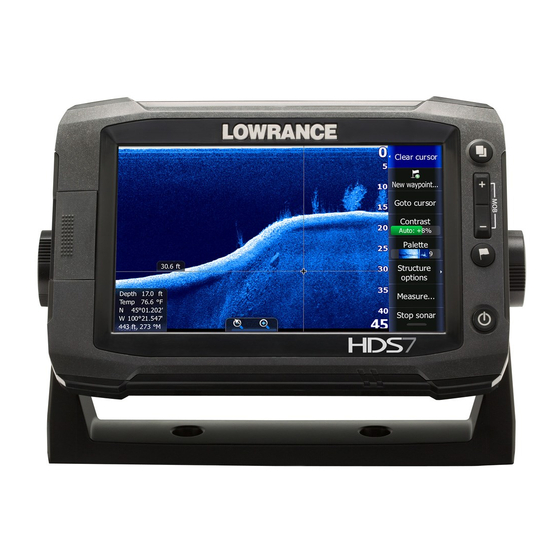
Page 9: Front - Controls
Front - controls Touchscreen Card reader door Pages key Zoom in / Zoom out key Mark / Waypoint key Power key HDS Gen2 Touch overview | HDS Gen2 Touch Installation Manual... -
Page 10: Rear - Connectors
StructureScan - connects to LSS-2 HD Transducer Power - also video for HDS-9 & 12, with optional adaptor Ethernet - two ports on HDS-9 & 12, one on 7 NMEA 2000 HDS Gen2 Touch overview | HDS Gen2 Touch Installation Manual... -
Page 11: Sd Card Slot
The card reader door should always be shut immediately after inserting or removing a card, in order to prevent possible water ingress. ¼ Note: The HDS-9 and 12 Displays have two card readers, the HDS-7 has one. HDS Gen2 Touch overview | HDS Gen2 Touch Installation Manual... -
Page 12: Check The Contents
Power cable Sun cover Fasteners - #6 x 1.5” (4x) Mounting bracket Parts Included, dependent on model 83/200 KHz transducer LSS-2 HD transducer 50/200 KHz transducer DVD - manuals 10 | Check the contents | HDS Gen2 Touch Installation Manual... -
Page 13: Display Installation
The display should be mounted so that the operator can easily use the controls and clearly see the display screen. Be sure to leave a direct path for all of the cables. Lowrance displays are high-contrast and anti-reflective, and are viewable in direct sunlight, but for best results install the display out of direct sunlight. -
Page 14: Bracket Mounting
Mount the display to the bracket using the knobs. Hand tighten only. The ratchet teeth in the bracket and display case ensure a positive grip and prevent the unit changing from the desired angle. 12 | Display Installation | HDS Gen2 Touch Installation Manual... -
Page 15: Flush Mounting
| 13 Display Installation | HDS Gen2 Touch Installation Manual... -
Page 16: Research
Best mounting location - undisturbed water flow Planing strake - avoid mounting behind here ¼ Note: Reverse the distance guides (1 & 3) from propeller where engine is of counterclockwise configuration. 14 | Display Installation | HDS Gen2 Touch Installation Manual... -
Page 17: Attaching The Transducer
Attach transducer to transom, using supplied stainless steel fasteners. Drill a 25mm (1”) hole above the waterline, large enough to pass the plug through. | 15 Display Installation | HDS Gen2 Touch Installation Manual... -
Page 18: Adjusting The Transducer
If the transducer is too high it may be seeing cavitation caused by the trailing edge of the transom. 16 | Display Installation | HDS Gen2 Touch Installation Manual... -
Page 19: Wiring
Be sure that the voltage of the power supply is compatible with the HDS Gen2 Touch display Warning: The HDS Gen2 Touch has a voltage rating of 12 V DC, it is not suited for use with 24V DC systems. Warning:... -
Page 20: Power Connection
Power connection HDS Gen2 Touch displays are designed to be powered by a 12 V DC system. They are protected against reverse polarity, under voltage and over voltage. The plug of the supplied power cable has two discrete cables exiting from it. - Page 21 The following demonstrates the power connections for a small system. HDS Displays HDS power cable Broadband radar interface SonicHub 12 V DC negative (-) 12 V DC postive (+) Accessory wake up line Vessel’s 12 V DC supply | 19 Wiring | HDS Gen2 Touch Installation Manual...
-
Page 22: Transducer Connection
Transducer connection All Combo HDS Gen2 Touch displays have internal Broadband and StructureScan sonar (chart only units require an external module for sonar). Navico transducers fitted with the 7 pin blue connector can be plugged directly into the corresponding blue socket labeled ‘Sonar’... -
Page 23: Ethernet Device Connection
5 ethernet ports. See page 31 for cable options. ¼ Note: When designing a system, take in to account the ports ‘lost’ when used for linking multiple NEP-2 modules together. | 21 Wiring | HDS Gen2 Touch Installation Manual... -
Page 24: Nmea 2000 Device Connection
NMEA 2000 device connection All HDS Gen2 Touch models are equiped with a NMEA 2000 port, which allows the receiving and sharing of a multitude of data from various sources. Essential network information • A NMEA 2000 network consists of a linear “backbone” from which “drop cables”... - Page 25 12 V DC GPS antenna HDS Display Broadband radar interface SonicHub ‘Drop’ cables (should not exceed 6m (20’) each) Power cable Micro-C T junctions Backbone Micro-C terminator (one male, one female) | 23 Wiring | HDS Gen2 Touch Installation Manual...
-
Page 26: Nmea 0183 Device Connection
Transmit: A (yellow), B (blue) Receive: A (orange), B (green) ground (shield) ¼ Note: The majority of NMEA 0183 devices communicate at 4,800 baud. AIS is a common exception, and normally transmits at 38,400 baud. 24 | Wiring | HDS Gen2 Touch Installation Manual... -
Page 27: Video In
Connecting video sources 12 V DC Video input adaptor cable RCA plug 12 V camera (3rd party) HDS power/data cable ¼ Note: Only connect NTSC and PAL video sources | 25 Wiring | HDS Gen2 Touch Installation Manual... -
Page 28: Software Setup
Enter a negative value, e.g. B) For Depth Below Transducer: no offset required. C) For Depth Below Surface (waterline): Set the distance from transducer to the surface: Enter a positive value., e.g. 26 | Software setup | HDS Gen2 Touch Installation Manual... - Page 29 Transducer type is used for selecting the transducer model that came with your unit. In some transducers with built-in temperature sensors, the temperature reading may be inaccurate if the wrong transducer is selected from the transducer type menu. | 27 Software setup | HDS Gen2 Touch Installation Manual...
-
Page 30: Touch Screen Calibration
Lowrance web site; www.lowrance.com An SD card and SD reader/writer are required for this. Detailed instructions for how to install the software are provided on the update web page. 28 | Software setup | HDS Gen2 Touch Installation Manual... -
Page 31: Dimensional Drawings
54 mm (2.13") 287 mm (11.30") 60.5 mm (2.38") HDS 12 Gen2 Touch 30.3 mm (1.19") 328.1 mm (12.92") 60.9 mm (2.4") 351.0 mm (13.82") 62 mm (2.44") 82.8 mm (3.26") | 29 Dimensional drawings | HDS Gen2 Touch Installation Manual... - Page 32 Accessories Refer to website for latest accessories: www.lowrance.com NMEA 2000 Part number Description 000-0124-69 NMEA 2000 STARTER KIT 000-0119-88 N2KEXT-2RD 2’ (0.61M) EXTENSION CABLE 000-0127-53 N2KEXT-6RD 6’ (1.82M) EXTENSION CABLE 000-0119-86 N2KEXT-15RD 15’ (4.55M) EXTENSION CABLE 000-0119-83 N2KEXT-25RD 25’ (7.58M) EXTENSION CABLE...
- Page 33 000-11032-001 HDS-12 GEN2 TOUCH SUNCOVER 000-11019-001 HDS-7 GEN2 TOUCH GIMBAL BRACKET 000-11020-001 HDS-9 GEN2 TOUCH GIMBAL BRACKET 000-11021-001 HDS-12 GEN2 TOUCH GIMBAL BRACKET 000-11050-001 HDS GEN2 TOUCH FLUSH MOUNT KIT 000-10467-001 BRACKET KNOBS PAIR – NSS/GEN2T | 31 Accessories |...
- Page 34 Part Number Description 000-0127-49 HDS POWER CABLE 000-0124-70 HDS CONNECTOR CAPS 000-0127-50 HDS FUSE & FUSE HOLDER 32 | Accessories | HDS Gen2 Touch Installation Manual...
-
Page 35: Supported Data
129540 GNSS Sats In View 129794 AIS Class A Static and Voyage Related Data 129801 AIS Addressed Safety Related Message 129802 AIS Safety Related Broadcast Message 129808 DSC Call Information | 33 Supported data | HDS Gen2 Touch Installation Manual... -
Page 36: Nmea 0183
MTW VLW VHW Compass Receive Transmit HDG Wind Receive MWV MWD Transmit MWV AIS / DSC Receive MARPA Transmit TLL ¼ Note: AIS sentences are not bridged to or from SimNet. 34 | Supported data | HDS Gen2 Touch Installation Manual... -
Page 37: Specifications
Specifications Refer to website for updates to specifications: www.lowrance.com | 35 Specifications | HDS Gen2 Touch Installation Manual... - Page 40 N2584...