Table of Contents
Advertisement
Advertisement
Table of Contents

Related Manuals for Husqvarna CRT900


Summary of Contents for Husqvarna CRT900
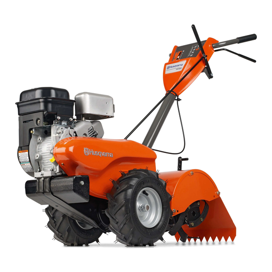
- Page 1 CRT900 Owner's Manual 532 43 95-06...
-
Page 2: Safety Rules
SAFETY RULES Safe Operation Practices for Walk-Behind Powered Ro ta ry Tillers TRAINING • Keep children and pets away. • Do not overload the machine capacity by attempting • Read the Owner’s Manual care ful ly. Be thor ough ly to till too deep at too fast a rate. -
Page 3: Table Of Contents
PRODUCT SPECIFICATIONS CUSTOMER RESPONSIBILITIES • Read and observe the safety rules. Gasoline Capacity: 3 Quarts • Follow a regular schedule in maintaining, caring for Unleaded Reg u lar (2,8L) and using your tiller. OIL (API-SG-SL): SAE 30 Above 32°F/0°C • Follow instructions under “Maintenance”... -
Page 4: Assembly
ASSEMBLY Your new tiller has been assembled at the factory with exception of those parts left unassembled for shipping purposes. To ensure safe and proper operation of your tiller all parts and hardware you assemble must be tightened securely. Use the correct tools as necessary to insure proper tightness. - Page 5 ASSEMBLY UNPACKING CARTON (See Fig. 2) • Grasp handle assembly. Hold in “up” position. Be sure handle lock remains in gearcase notch. Slide handle assembly into position. CAUTION: Be careful of exposed sta ples when handling or disposing of cartoning material. HANDLE ASSEMBLY "UP"...
- Page 6 ASSEMBLY CONNECT SHIFT ROD (See Fig. 7) ATTACH CLUTCH CABLE (See Fig. 6) • Insert end of shift rod into hole of shift lever indicator. • Hook end of clutch cable through hole in control bar bracket. • Insert hairpin clip through hole of shift rod to secure. CONTROL BAR SHIFT HAIRPIN...
-
Page 7: Product View
OPERATION KNOW YOUR TILLER READ THIS OWNER'S MANUAL AND SAFETY RULES BEFORE OPERATING YOUR TILLER. Compare the illustrations with your tiller to familiarize yourself with the location of various controls and adjustments. Save this manual for future reference. These symbols may appear on your Tiller or in literature supplied with the product. Learn and understand their meaning. -
Page 8: To Use Tiller
OPERATION The operation of any tiller can result in foreign objects thrown into the eyes, which can result in severe eye damage. Always wear safety glasses or eye shields before starting your tiller and while tilling. We recommend a wide vision safety mask for over spectacles or standard safety glasses. -
Page 9: Check Engine Oil Level
OPERATION • When you have completed your turn-around, release ADD GASOLINE the drive control bar and lower handle. Place shift • Fill fuel tank to bottom of filler neck. Do not overfill. lever in till position and move throttle control to de sired Use fresh, clean, regular un lead ed gasoline with a speed. -
Page 10: Tilling Hints
OPERATION • When engine starts, slowly move choke control to • Soil conditions are important for proper tilling. Tines will "RUN" position as engine warms up. not readily penetrate dry, hard soil which may con trib ute to excessive bounce and difficult handling of your tiller. NOTE: A warm engine requires less choking to start. -
Page 11: Maintenance Schedule
MAINTENANCE MAINTENANCE SCHEDULE FILL IN DATES AS YOU COMPLETE SERVICE DATES REGULAR SERVICE Check Engine Oil Level Change Engine Oil Oil Pivot Points Inspect Spark Arrester / Muffler Inspect Air Screen Clean or Replace Air Cleaner Cartridge Clean Engine Cylinder Fins Replace Spark Plug RH Gear Case Grease Fitting (1oz.) 1 - Change more often when operating under a heavy load or in high ambient temperatures. -
Page 12: Maintenance
MAINTENANCE Disconnect spark plug wire before performing any maintenance (except car bu re tor adjustment) to prevent accidental start ing of engine. Prevent fires! Keep the engine free of grass, leaves, spilled oil, or fuel. Re move fuel from tank before tipping unit for maintenance. - Page 13 MAINTENANCE COOLING SYSTEM (See Fig. 19) Your engine is air cooled. For proper engine performance and long life keep your engine clean. • Clean air screen frequently using a stiff-bristled brush. • Keep cylinder fins, levers, and linkage free of dirt and chaff.
-
Page 14: Service & Adjustments
SERVICE AND ADJUSTMENTS CAUTION: Disconnect spark plug wire from spark plug and place wire where it cannot come into contact with plug. TILLER TO ADJUST HANDLE HEIGHT (See Fig. 20) Select handle height best suited for your tilling conditions. Handle height will be different when tiller digs into soil. CLEVIS PIN •... -
Page 15: Service And Adjustments
SERVICE AND ADJUSTMENTS TO REPLACE GROUND DRIVE BELT GROUND DRIVE BELT ADJUSTMENT (See Fig. 23) (See Fig. 23) • Remove belt guard (See “TO REMOVE BELT GUARD” For proper belt tension, the extension spring should in this section of this manual). have about 5/8 inch stretch when drive control bar is in •... - Page 16 SERVICE AND ADJUSTMENTS TINE REPLACEMENT (See Figs. 24, 25 and • To maintain the superb tilling performance of this ma- chine the tines should be checked for sharpness, wear, and bending, particularly the tines which are next to the transmission. If the gap between the tines ex ceeds CAUTION: Tines are sharp.
-
Page 17: Service & Adjustments
SERVICE AND ADJUSTMENTS ENGINE TO AD JUST CARBURETOR The carburetor has been preset at the factory and ad just ment should not be necessary. However, engine per for mance can be affected by dif fer enc es in fuel, tem per a ture, al ti tude or load. -
Page 18: Storage
STORAGE Immediately prepare your tiller for storage at the end of the ENGINE OIL season or if the unit will not be used for 30 days or more. Drain oil (with engine warm) and replace with clean oil. (See “ENGINE” in the Maintenance section of this man ual). WARNING: Never store the tiller with gasoline in the tank inside a build ing CYLINDER(S) -
Page 19: Troubleshooting
TROUBLESHOOTING POINTS PROBLEM CAUSE CORRECTION Will not start 1. Out of fuel. 1. Fill fuel tank. 2. Engine not “CHOKED” properly. 2. See “TO START ENGINE” in Operation section. 3. Engine flooded. 3. Wait several minutes before attempting to start. 4. -
Page 20: Repair Parts-Tiller
REPAIR PARTS TILLER - - MODEL NUMBER CRT900 (96093001301), PRODUCT NUMBER 960 93 00-13 HANDLE ASSEMBLY PART PART DESCRIPTION DESCRIPTION 532 42 76-43 Grip, Handle 532 08 67-77 Screw, Hex Washer SLT#10-24 x .50 532 15 92-28 Bar Assembly, Control... - Page 21 REPAIR PARTS TILLER - - MODEL NUMBER CRT900 (96093001301), PRODUCT NUMBER 960 93 00-13 MAINFRAME, LEFT SIDE PART PART DESCRIPTION DESCRIPTION 873 22 06-00 Nut, Hex 3/8-16 532 13 28-01 Belt, V 532 43 24-20 Shield, Inner Belt Guard RT...
- Page 22 REPAIR PARTS TILLER - - MODEL NUMBER CRT900 (96093001301), PRODUCT NUMBER 960 93 00-13 MAINFRAME, RIGHT SIDE PART PART DESCRIPTION DESCRIPTION 873 97 05-00 Locknut, Hex, Flange 5/16-18 - - - - - - - - Engine, Briggs & Stratton 532 10 23-32 Bracket, Reinforcement RH Model No.
- Page 23 REPAIR PARTS TILLER - - MODEL NUMBER CRT900 (96093001301), PRODUCT NUMBER 960 93 00-13 TRANSMISSION 13 15 18 32 transmission_19.5b_r1 PART PART DESCRIPTION DESCRIPTION 532 18 85-54 Transmission Assembly 532 15 07-37 Ground Shaft Assembly (In cludes Key Nos. 2-53) 532 14 30-08 Bearing, Shaft, Ground Drive R.H.
- Page 24 REPAIR PARTS TILLER - - MODEL NUMBER CRT900 (96093001301), PRODUCT NUMBER 960 93 00-13 TINE SHIELD PART PART DESCRIPTION DESCRIPTION 873 90 05-00 Nut, Lock Hex Flange 5/16-18 532 00 44-40 Hinge 532 00 83-93 Pin, Stake, Depth 872 14 04-04 Bolt, Carriage 1/4-20 x 1/2 Gr. 5...
- Page 25 REPAIR PARTS TILLER - - MODEL NUMBER CRT900 (96093001301), PRODUCT NUMBER 960 93 00-13 TINE ASSEMBLY PART PART DESCRIPTION DESCRIPTION 532 13 27-22 Assembly, Hub and Plate, R.H. 532 00 44-59 Tine, Outer, L.H. 532 13 26-73 Clevis Pin 532 00 65-55 Tine, Inner, R.H.
- Page 26 REPAIR PARTS TILLER - - MODEL NUMBER CRT900 (96093001301), PRODUCT NUMBER 960 93 00-13 DECALS PART DESCRIPTION 532 42 91-96 Decal, Belt Guard Badge 532 43 23-62 Decal, Husqvarna, Control Panel 532 43 14-65 Decal, Control Tine 532 42 83-28 Decal, Tine Shield...
- Page 27 SERVICE NOTES...
-
Page 28: Warranty
(e.g., engines and transmissions) are excluded from coverage, and other limitations apply, as described in this document. Husqvarna will repair or replace at its discretion, any defective product or part covered by the Limited Warranty, free of charge at any authorized Husqvarna Servicing Dealer/Center using original OEM Husqvarna replacement parts, subject to the limitations and exclusions described below. - Page 29 Husqvarna unit to an authorized Husqvarna Servicing Dealer/Center and arrange for pick-up or return of your unit after the repairs have been made. If you do not know the location of your nearest authorized Husqvarna Servicing Dealer, call Husqvarna, at 1-800-487-5951 during the hours of 8:00 AM to 8:00 PM Eastern Standard Time, or visit www.husqvarna.com.
- Page 30 ** See reference 1 (b) of the warranty statement. RZ - Two (2) Year Consumer warranty, parts & labor, with Hydro-Gear Distributor network. EZ - One (1) Year Commercial warranty, parts & labor, with Husqvarna. Two (2) Year Consumer warranty, parts & labor, with Hydro-Gear Distributor network.
-
Page 31: Warranty
** See reference 1 (b) of the warranty statement. RZ - Two (2) Year Consumer warranty, parts & labor, with Hydro-Gear Distributor network. EZ - One (1) Year Commercial warranty, parts & labor, with Husqvarna. Two (2) Year Consumer warranty, parts & labor, with Hydro-Gear Distributor network. - Page 32 10.11.10 CL Printed in the U.S.A.