Table of Contents
Advertisement
Instruction manual
Please read these instructions
carefully and make sure you under-
stand them before using this machine.
Anleitungshandbuch
Bitte lesen Sie diese Anleitungen
sorgfältig durch und vergewissern Sie
sich, daß Sie diese verstehen, bevor
Sie die Maschine in Betrieb nehmen.
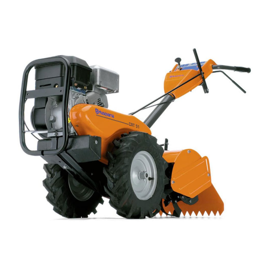
CRT51
Manuel d'instructions
S'il vous plaît lisez soigneusement et
soyez sûr de comprende ces
instructions avant d'utiliser cette
machine.
Manual de las instrucciones
Por favor lea cuidadosamente y
comprenda estas intrucciones antes
de usar esta maquina.
Manuale di istruzioni
Prima di utilizzare la macchina leggete
queste istruzioni con attenzione ed
accertatevi di averle comprese bene.
Instructieboekje
Lees deze instructies aandachtig en
zorg dat u ze begrijpt voordat u deze
machine gebruikt.
Advertisement
Table of Contents

Related Manuals for Husqvarna crt51


Summary of Contents for Husqvarna crt51
- Page 1 CRT51 Instruction manual Please read these instructions carefully and make sure you under- stand them before using this machine. Anleitungshandbuch Bitte lesen Sie diese Anleitungen sorgfältig durch und vergewissern Sie sich, daß Sie diese verstehen, bevor Sie die Maschine in Betrieb nehmen.
- Page 2 Safety rules. Sicherheitsvorschriften. Règles de sécurité. Assembly. Zusammenbau. Montage. Start and operation. Start und betrieb. Mise en marche et conduite. Maintenance. Wartung . Entretien. Repair and adjustment. Reparatur und einstellung. Réparations et réglages. Troubleshooting. Störungssuche. Recherche des pannes. Technical data. Techinische daten.
- Page 3 1. SAFETY RULES TRAINING • Read the instructions carefully. Be familiar with the controls and the proper use of the equipment; • Never allow children or people unfamiliar with these instructions to use the machine. Local regulations can restrict the age of the operator. •...
- Page 4 1. RÈGLES DE SÉCURITÉ FORMATION • Lisez soigneusement ces instructions. Familiarisez-vous avec les commandes pour apprendre a utiliser correctement voter équipement; • N'autorisez jamais que des enfants utilisent votre machine. Ne permettez pas que des adultes l'utilisent s'ils n'ont pas reçu les instructions nécessaires.
- Page 5 1. REGLAS DE SEGURIDAD ENTRENAMIENTO • Lea las instucciones cuidadosamente. Familiarícese completamente con los controles y con el uso adecuado del equipo; • Nunca permita que los niños operen el equipo. Nunca permita que los adultos operen el equipo sin los conocimientos adecuados.
- Page 6 These symbols may appear on your machine or in the literature supplied with the product. Learn and understand their meaning. Diese Symbole finden Sie auf Ihrer Maschine oder in Unterlagen, die mit dem Produkt ausgehändigt wurden. Bitte machen Sie sich mit deren Bedeutung vertraut. Ces symboles peuvent se montrer sur votre machine ou dans les publications fournies avec le produit.
- Page 7 2. Be sure handle lock remains in gearcase notch. Be careful not to stretch or kink cables. (fig. 3-inset) first, with head of bolt on L.H. side of tiller. Insert front pivot bolt. Lower the handle assembly.
- Page 8 Connect clutch cable Connect clutch cable to control bar bracket as shown (fig. 4). Tire pressure Reduce tire pressure to 20 PSI (Tires were overinflated for shipping purposes). If tire pressures are not equal, tiller will pull to one side. Inset...
- Page 9 1. Getriebegehäuse-Aussparung 2. Handgriffsperre 3. Handgriff (obere Stellung) 4. Schalthebel 5. Handgriff (untere Stellung) 6. Hangriffsperrenhebel Abb. 1 Abb. 2 Montage des Handgriffs a. Eine Handgriffsperre (mit den Zähnen nach außen) in die Aussparung des Getriebegenhäuses einpassen (Abb. 1). Die glatte Seite der Handgriffsperre mit Fett schmieren. Auf diese Weise wird die Sperre in der Aussparung gehalten, bis der Griff angebracht worden ist.
- Page 10 2 2 2 2 2 1. Schaltstange 2. Haarnadelklemme 3. Schalthebelanzeiger 4. Handgriffmontagesatz 5. Wagenbolzen und Kontermutter 6. Handgriffplatte 7. Schlitz 8. Getriebegehäuse 9. Handgriffsperre 10. Unterlegscheibe 11. Handgriffsperrenhebel 12. Gelenkbolzen Abb 3 Abb 4 Anschluß der Schaltstange a. Das Ende der Schaltstange in das Loch der Schalthebelanzeige einsetzen.
- Page 11 1. Encoche du carter de la boîte de vitesses 2. Couvercle du guidon 3. Guidon (position haute) 4. Levier de changement de vitesses 5. Guidon (position basse) 6. Levier de blocage du guidon Figure 1 Figure 2 Montage du guidon a.
- Page 12 1. Barre d'embrayage 2. Pince en épingle à cheveux 3. Assemblage du manche 4. Boulon à tête bombée et collet carré et contre-écrou 5. Boulon de véhiclue et écrou de blocage 6. Base du guidon 7. Fente 8. Carter de la boîte de vitesses 9.
- Page 13 1. Schakelkastsleuf 2. Hendelvergrendeling 3. Hendel (hoge positie) 4. Schakelhendel 5. Hendel (lage positie) 6. Hendelvergrendelingarm Figuur 1 Figuur 2 Handvat monteren a. Monteer de eerste hendelvergrendeling (met de tanden naar buiten wijzend) in de sleuf in de schakelkast (fig. 1). Breng vet aan op de galdde kant van de hendelvergrendeling.
- Page 14 1. Schakelstang 2. Splitpen 3. Schakelhendelindicator 4. Hendeleenheid 5. Slotschroef en borgmoer 6. Hendelbasis 7. Sleuf 8. Schakelkast 9. Hendelvergrendeling 10. Sluitring 11. Hendelvergrendeling hefboom 12. Zwenkbout Figuur 3 figuur 4 a. Steek het einde van de schakelstang in het gat van de b.
- Page 15 1. Muesca de caja de engranajes 2. Bloqueo del manillar 3. Manillar (posició alta) 4. Palanca de cambio 5. Manillar (posición baja) 6. Palanca de bloqueo de manillar Figura 1 Figura 2 Instalación del manillar a. Introduzca un bloqueo del manillar (con los dientes hacia afuera) en la muesca de la caja de engranajes (fig.
- Page 16 2 2 2 2 2 1. Barra de cambio 2. Chaveta hendida 3. Indicador de palanca de cambio 4. Manillar completo 5. Tornillo de carruaje y tuerca de seguridad 6. Base de manillar 7. Ranura 8. caja de engranajes 9. Bloqueo de manillar 10.
- Page 17 1. Tacca 2. Fermo del manubrio 3. Manubrio (posizione superiore) 4. Leva del cambio 5. Manubrio (posizione inferiore) 6. Leva di fermo del manubrio. Figure 1 Figure 2 Montaggio del manubrio a. Montare uno dei fermi (con i denti rivolti verso l'esterno) nella tacca (fig.
- Page 18 2 2 2 2 2 1. Asta del cambio 2. Graffa a U 3. Selettore di marcia 4. Manubrio 5. Dado e bullone di fermo 6. Base del manubrio 7. Fessura 8. Scatola 9. Fermo del manubrio 10. Rondella 11. Leva del fermo 12.
- Page 19 1. Handle Bar 2. Throttle control 3. Shift lever 4. Drive control bar 5. Tine shield 6. Engine 7. Wheel 8. Model plate 1. Handgriff 2. Gashebel 3. Schalthebel 4. Antriebshebel 5. Zinkenschutz 6. Motor 7. Räder 8. Typenschild 1. Guidon 2.
- Page 20 3. Start und Betrieb 3. Starten en rijden NOTE! Before operating your tiller for the first time, study this section and the "1. Safety instructions". Check engine oil level a. With engine level, remove engine oil filler plug (fig. 5) b.
- Page 21 1. Niveau d'huile 2. Bouchon de remplissage d'huile 3. Bouchon du réservoir d'essence 1. Oliepeil 2. Olievuldop 3. Dop benzinetank Figure 5 Figuur 5 Figure 6 Figuur 6 NOTA! Avant de conduire votre fraiseuse pour la première fois, étudiez le présent chapitre et les "1. Cosignes de sécurité". Vérifiez le niveau d'huile du moteur a.
- Page 22 1. Nivel de aceite 2. Tapón de llenado de aceite 3. Tapón de depósito de gasolina 1. Livello dell'olio 2. Tappo dell'olio 3. Tappo serbatoio carburante Figura 5 Figure 5 figura 6 Figure 6 ¡NOTA! Antes de utilizar su cultivadora por primera vez, estudie esta sección y las "1.
- Page 23 1. Starter handle 2. Choke lever 3. Spark plug wire and cover 4. Shift lever indicator 5. Drive control bar "disengaged" position 6. Drive control bar "engaged" position 7. Throttle control 8. Handle grip Figure 7 Figure 8 Starting the engine a.
- Page 24 1. Starthandgriff 2. Chokehebel 3. Zündkerzenkabel und Kerzenstecker 4. Schalthebelanzeiger 5. Antriebshebel ausgekuppelt 6. Antriebshebel eingekuppelt 7. Gashebel 8. Handgriff Abb. 7 Abb. 8 Motorstart a. Zündkerzenkabel und Kerzenstecker (Abb. 7) lösen. b. Schalthebel auf "N" (Neutralstellung) einstellen (Abb. 8). c.
- Page 25 1. Poignée du démarreur 2. Manette du starter 3. Câble et couvercle de la bougie 4. Indicateur du levier de vitesses 5. Barre de commande débrayée 6. Barre de commande embrayée 7. Accélérateur 8. Price du guidon Figure 7 Figure 8 Démarrage du moteur a.
- Page 26 3 3 3 3 3 1. Starthendel 2. Chokehendel 3. Bougiedraad en kap 4. Schakelhendel indicator 5. Stuurhendel in "ontkoppelde" positie 6. Stuurhendel in "ingeschakelde" positie 7. Gashendel 8. Handgreep Figuur 7 Figuur 8 De motor starten a. Verbind de bougiekabel en kap (fig. 7). b.
- Page 27 1. Manija de arranque 2. Palanca de estrangulación 3. Cable de bujia con cubierta 4. Indicador de palanca de cambio 5. Barra de control de propulsión en posición "desengranada" 6. Barra de control de propulsión en posición "engranada" 7. Mando de aceleración 8.
- Page 28 3 3 3 3 3 1. Maniglia di avviamento 2. Levo dello choke 3. Cavo e cappuccio della candela 4. Indicatore della marcia selezionata 5. Leva del comando di avanzamento in posizione "disinserto" 6. Levo del comando di avanzamento in posizione "inserito"...
- Page 29 Stopping tines and engine a. Tiller movement and tines will stop when drive control bar b. Move shift lever indicator (fig. 11 -inset A) to "N" (Neutral) c. To stop engine, move throttle control (fig. 10) to "STOP"...
- Page 30 "ball-up" or clump during tilling. Wait until the soil is less wet in order to achieve the best results. For easier handling of your tiller, leave about 8 inches of untilled soil between the first and second tilling passes. The third pass will be between the first then second and etc.
- Page 31 Ausschnitt A Ausschnitt B 1. Äußere Seitenabdeckung 10. Transportstellung 2. Mutter "A" 11. Flaches Oberflächen- 3. Mutter "B" 4. Antriebshebel 12. Oberflächenfräsen 5. Handgriff 13. Tieffräsen 6. Gashebel 14. Tiefes Tieffräsen 15. Höhenverstellstange 7. Schalthebelanzeiger 8. Höhenverstellstange 16. Entriegelung 9. Höhenverstellstangenstift 17.
- Page 32 3 3 3 3 3 Abb. 12 Bodenfräsen Bodenfräsen a. Den Höhenverstellstangenstift (Abb. 11 - Ausschnitt C) entriegeln. Höhenverstellstange hochziehen, um die Frästiefe zu erhöhen. Den Stift wieder in das Loch der Höhenverstellstange einsetzen und in dieser Stellung verriegeln (Abb. 11 - Ausschnitt C). b.
- Page 33 Encart A Encart B 10. Position de transport 11. Fraisage très léger 1. Protection Latérale 12. Fraisage léger 2. Écrou A 13. Fraisage très profond 3. Écrou B 14. Fraisage profond 4. Barre de commande 15. Barre de réglage en hau- 5.
- Page 34 3 3 3 3 3 Figure Fraisage Fraisage a. Desserrez la clavette de la barre de réglage en hauteur (fig. 11, encart C). Poussez la barre de réglage en hauteur vers le haut pour augmenter la profondeur de fraisage. Placez la clavette dans le trou de la barre de réglage en hauteur pour la bloquer.
- Page 35 Inzet A Inzet B 1. Äußere Seitenabdeckung 10. Transportstellung 2. Mutter "A" 11. Flaches Oberflächenfräsen 3. Mutter "B" 12. Oberflächenfräsen 4. Antriebshebel 13. Tieffräsen 5. Handgriff 14. Tiefes Tieffräsen 6. Gashebel 15. Höhenverstellstange 7. Schalthebelanzeiger 16. Entriegelung 8. Höhenverstellstange 17. Verriegelung 9.
- Page 36 3 3 3 3 3 Figuur Bewerken Bewerken a. Ontgrendel de dieptestaakpen (fig. 11 inzet c). Trek de b. Zet de schakelhendelindicator (fig. 11 - inzet A) in de "T" c. Hou de stuurhendel tegen de hendel (fig. 10) om te d.
- Page 37 Detalle A Detalle B 1. Cubierta protectora exterior 10. Posición de transporte 2. Tuerca " A" 11. Laboreo más superficial 3. Tuerca "B" 12. Laboreo superficial 4. Barra de contorl de propulsión 13. Laboreo profundo 5. Manillar 14. Laboreo más profundo 6.
- Page 38 3 3 3 3 3 Figura Laboreo a. Saque el pasador de la barra de profundidad (fig. 11 - b. Desplace el indicador de palanca de cambio (fig. 11 - c. Sujete la barra d. Mueva el control de aceleración (fig. 10) a "FAST" ¡ADVERTENCIA! Suelte siempre la barra de control de propulsión antes de desplazar al palanca de cambio a otra posición.
- Page 39 Encart A Encart B 10. Posizione di trasporto 1. Disco salvapianta 11. Aratura superficiale 2. Dado A 3. Dado B 12. Aratura poco profonda 13. Aratura intermedia 4. Leva comando avanzamento 5. Manubrio 14. Aratura profonda 15. Regolatore di profondità 6.
- Page 40 3 3 3 3 3 Figure Aratura a. Disinserire il perno del regolatore di profondità (fig. 11 b. Portare la leva del cambio (fig. 11 inserto A) su "T" c. Tenere la leva di controllo dell'avanzamento contro il d. Portare il comando del gas (fig. 10) sul "FAST" (veloce). ATTENZIONE! Prima di cambiare marcia disinserire sempre la leva di avanzamento.
- Page 41 Cultivating Cultivating is destroying the weeds between rows to prevent them from robbing nourishment and moisture from the plants. Best digging depth is 1" to 3". Lower outer side shields to protect small plants from being buried. Cultivate up and down the rows at a speed which will alow tines to uproot weeds and leave the ground in rough condi- tion, promoting no ruther growth of weeds and grass (fig.
- Page 42 Once a season, lubricate the right hand gear case grease fitting with 1 oz. of wheel bearing grease. Finish Keep tiller finish and wheels free of gasoline, oil, etc. Protect painted surfaces with automotive type wax. WARNUNG! Vor jeder Wartungsarbeit (ausgenommen Vergaserein- stellung) sind Zündkerzenkabel und Kerzenstecker zu...
- Page 43 Figure 14 Abb. 14 Storage Keep your tiller stored in a dry area. To avoid the formation of gum deposits in the fuel system it should be drained if the machine is not to be used for 30 days or longer.
- Page 44 1. Bouchon de vidange d'huile 2. Bouchon de remplissage d'hile 3. Jauge d'huile 1. Olie-aftappug 2. Olie-vuldop 3. Oliepeil Figure 14 Figuur 14 Rangement Rangez votre fraiseuse au sec. Pour éviter les dépôts de gomme dans le circuit d'essence il faut le vidanger si la machine ne doit pas être utilisée pendant 30 jours ou plus.
- Page 45 1. Tapón de vaciado de aceite 2. Tapón de llenado de aceite 3. Nivel de aceite 1. Tappo per lo scarico dell'olio 2. Tappo rifornimento olio 3. Livello dell'olio Figure 14 Figura 14 Almacenamiento Guarde su cultivadora en lugar seco. formación de depósitos en sistema de combustible, deberá...
- Page 46 4 4 4 4 4 Lubrication chart Oil pivot points 1. Wheels 2. Idler bracket 3. Throttle control Figure 15 Maintenance schedule Check engine oil level Change engine oil Oil pivot points Spark arrester muffler Inspect air screen Air cleaner Clean engine cylinder fins Replace spark plugs First 2 hours...
- Page 47 Schmierplan Schmieren der Lagerspitzen 1. Räder 2. Leerlaufarm 3. Gashebel Abb. 15 Wartungsplan Motorölstand Kontrollieren Morotöl wechseln Lagerspitzen schmieren Funkenlöschen im Auspuffrohl Luftgitter kontrollieren Luftreiniger kontrollieren Zylinderrippen des Motors reinigen Zundkerzen montieren Beim erstenmal Ver jedem Alle 5 Stunden 2 Stunden Gebrauch •...
- Page 48 4 4 4 4 4 Plan de graissage Points de friction à graisser 1. Roues 2. Support de pignon 3. Accélérateur Figure 15 Schema d'entretien Vérifier le neveau d'huile Changer l'huile Points de friction à graisser Pare-étincelles du pot d'échappement Inspection du filtre à...
- Page 49 Smeerschema Olie de draaipunten 1. Wielen 2. Steun spanrol 3. Gashendel Figuur 15 Onderhoudsschema Controleer het motoroliepeil Ververs de motorolie Olie de draaipunten Vonkdover knaldemper Controleer het luchtscherm Luchtfilter Reinig de koelribben van de moror Vervand de bougies Nade eerst Telkens voor 2 uur gebruik...
- Page 50 4 4 4 4 4 Hojo de lubricación Lubrique los puntos de giro ruedas Support de polea tensor Mando de aceleración Figura 15 Esquema de mantenimiento Control del nivel de aceite Cambio de aceite Engrase de puntos de giro Silenciador con apagachispas incorporado Inspección de filtro de aire Purificador de aire Limpieza de aletas del cilindro...
- Page 51 Schema di lubrificazione Lubrificare snodi e attacchi 1. Route 2. Braccio del folle 3. Comando del gas Figure 15 Schema manutenzione Controllo livello olio motore Cambio dell'olio Lubrificazione snodi e attacchi Candela, arresto e marmitta Ispezione prese d'aria Depuratore dell'aria Pulizia flange raffreddamento del cilindro Sostituzione della candela Dopo 2 ore...
- Page 52 16). Retighten handle lock lever. NOTE! Select handle height suitable for you and your tilling condi- tions. Handle height will change when tiller digs into the soil. WARNING! Stop the engine and remove the spark plug wire and cover from the spark plug (fig. 7) before cleaning out the tines by hand.
- Page 53 1. Handgriff (untere Einstellung) 2. Handgriff (obere Einstellung) 3. Handgriffsperrenhebel 4. Riemenführung 5. Antriebsriemenscheibe 6. Spannrolle 7. Zugfeder 8. Kraftübertragungssscheibe 9. Antriebsseil 10. Seilklemmenschraube Abb. 16 Einstellen des Handgriffs Handgriffsperrenhebel lösen (Abb. 16). Der Handgriff ist in mehreren stufen Handgriffsperrenhebel wieder festziehen. ACHTUNG! Der Handgriff sollte mit Rücksicht auf eine bequeme Arbeitsstellung eingestellt werden.
- Page 54 5 5 5 5 5 1. Guidon (position "basse") 2. Guidon (position "haute") 3. Levier de blocage du guidon 4. Guide-courroie 5. Poulie du moteur 6. Poulie du galet-tendeur 7. Ressort de traction 8. Poulie de transmission 9. Câble de commande 10.
- Page 55 1. Hendel ("lage" positie) 2. Hendel ("hoge" positie) 3. Hendelvergrendeling 4. Riemgeleider 5. Motorriemschijf 6. Riemschijf spanrol 7. Trekveer 8. Riemschijf transmissie 9. Stuurhendel kabel 10. Kabelklemschroef Figuur 16 Positie hendel Maak de hendelvergrendelingarm los (fig. 16). De hendel kan in verschillende posities tussen "hoge" en "lage" gezet worden (fig.
- Page 56 5 5 5 5 5 1. Manillar (posición baja) 2. Manillar (posición alta) 3. Palanca de bloqueo del manillar 4. Guía de correa 5. Polea del motor 6. Polea del motor 7. Muelle de extensión 8. Plea de transmisión 9. Cable de control de propulsión 10.
- Page 57 1. Manubrio (posizione abbassata) 2. Manubrio (posizione sollevata) 3. Leva di bloccaggio del manubrio 4. Guida della cinghia 5. Puleggia del motre 6. Puleggia folle 7. Molla di tensione 8. Puleggia transmissione 9. Cavo comando avanzamento 10. Vite di fermo del cavo Figure 16 Posizione del manubrio Allentare la leva di bloccaggio del manubrio (fig.
- Page 58 Remove old belt by slipping from idler pulley (fig. 17) first. e. Place new belt in groove to transmission pulley (large A badly worn tine causes your tiller to work harder and dig shallower. Most important, worn tines can not chop and shred organic matter as effectively nor bury it as deeply as good tines.
- Page 59 1. Riemenabdeckung 2. Schrauben 3. Schrauben 4. Haarnadelklemme und Sicherungsstift 5. Sechskantmutter (hinter dem Seil) 6. Neue Zinke 7. Verschlissene Zinke 8. Geschärfte Schneide 9. Haarnadelklemme 10. Sicherungsstift Abb. 18 Abb. 19 Abb. 20 Tine a. Haarnadelklemme und Sicherungsstift (Abb. 18 von der b.
- Page 60 5 5 5 5 5 1. Protége-courroie 2. Vis 3. Vis 4. Pince en épingle à cheveux et clavette de retenue 5. Écrou hexagonal (placé derrière le pneu 6. Dent neuve 7. Dent usée 8. Tranchant 9. Pince en épingle à cheveux 10.
- Page 61 1. Riembeveiliging 2. Schroef 3. Schroef 4. Splitpen en opsluitstift 5. Zeshoekige moer (achter de band gemotnteerd) 6. Nieuwe tand 7. Versleten tand 8. Scherpe snede 9. Splitpen 10. Opsluitstift Figuur 18 Figuur 19 Figuur 20 Tand a. Verwijder de splitpen en de opsluitstift (fig. 18) van de b.
- Page 62 5 5 5 5 5 1. Cubierta de la correa 2. Tornillo 3. Tornillo 4. Chaveta hendida y pasador de seguridad 5. Tuerca hexagonal (situado detrás del neumático) 6. Diente nuevo 7. Diente gastado 8. Borde afilado 9. Chaveta hendida 10.
- Page 63 1. Copricinghia 2. Vite 3. Vite 4. Graffa a U e perno di fermo 5. Dado esagonale (posto dietro la ruota) 6. Nuova lama 7. Lama danneggiata 8. Bordo affilato 9. Graffa a U 10. Perno di fermo Figure 18 Figure 19 Figure 20 Tine...
- Page 64 6. Troubleshooting 6. Búsqueda de averías 6. Ricerca guasti Will not start or hard to start • No gasoline in fuel tank Fill tank with gasoline. • Throttle control not set properly Place throttle control in "FAST" position. • Choked improperly, flooded engine Move choke control to "RUN"...
- Page 65 Ne veut pas démarrer ou est difficile à démarrer • Pas d'essence dans le réservoir Remplissez le réservoir d'essence • L'accélérateur n'est pas dans la bonne position Placez l'accélérateur en position rapide "FAST" • Le starter du moteur n'est pas utilisé correctement, le moteur est noyé...
- Page 66 6 6 6 6 6 No arranca o difícil de arrancar • Depósito de gasolina vacio Llene el depósito con gasolina Mando de aceleración no ajustado debidamente • Ponga el mando de aceleración en la posición “FAST” (acelerada) • Uso incorrecto de estrangulador, motor ahogado Desplace el mando del estrangulador a la posición “RUN”...
- Page 67 TECHNICAL DATA Type: CRT51 Rear-mounted Cultivator Rear drive: Drag action (friction) of the rotor blades in the soil. Clutch controls on the handlebar. Single forward speed. Automatic safety cutout (dead man's control). Weight: 80 kg Transport wheels: (supporting wheels) Diameter 40 cm (16") Mounted in the front of arrester bar.
- Page 68 ESPECIFICACIONES TECNICAS Type: CRT51 Cultivador impulsado por motor. Avance: El cultivador avanza con la fricción de las cuchillas contra la tierra. Mando de embrague y desmbrague en el manillar. 1 velocidad hacia adelante. Dispositivo de hombre muerto. Peso: 80 kg...
- Page 72 532175641 Rev. 1 11.10.00 TR Printed in U.S.A.