Table of Contents
Advertisement
Quick Links
Advertisement
Table of Contents

Related Manuals for GE GEK 106168E


Summary of Contents for GE GEK 106168E
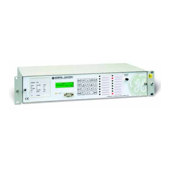
- Page 1 ÿ GE Power Management Digital Breaker Failure Protection Digital Breaker Failure Protection Digital Breaker Failure Protection Digital Breaker Failure Protection Instructions Instructions Instructions Instructions GEK 106168E GEK 106168E GEK 106168E GEK 106168E...
- Page 2 $Q\WKLQJ \RX FDQ·W ILQG" $Q\WKLQJ QRW FOHDU HQRXJK"...
-
Page 4: Table Of Contents
5.1.3. Internal Construction ... 25 5.2. O ... 27 PERATING HEORY 5.2.1. Magnetic Module ... 27 5.2.2. CPU Board ... 27 5.2.3 Power Supply ... 28 5.2.4 Keyboard and Display ... 28 ACCEPTANCE TESTS... 29 6.1. C ONNECTIONS AND ECESSARY 6.2. V ... - Page 5 6.9.5 Neutral Overcurrent Unit Test... 35 6.10. R ELAY EASUREMENT ESTS 6.10.1. Current Measurement... 37 6.10.2. Timing Measurement ... 37 INSTALLATION AND MAINTENANCE ... 39 7.1. I ... 39 NSTALLATION 7.2. C ONNECTION ROUND AND 7.3. M ... 39 AINTENANCE KEYBOARD AND DISPLAY...
-
Page 6: List Of Figures
LIST OF FIGURES LIST OF FIGURES Figure 1. Breaker Failure Logic (189C4114 Sheet 2) Figure 2. External Connections (189C4114 Sheet 1) Figure 3. Front View (226B7412 Sheet 9) Figure 4. Rear View (226B7412 Sheet 10) Figure 5. Dimensions Diagram (226B6086 sheet 10) Figure 6. - Page 7 LIST OF FIGURES DBF Breaker Failure Protection GEK-106168E...
-
Page 8: General Description And Application
1. 1. 1. 1. 1.1. GENERAL DESCRIPTION The DBF system is a microprocessor based breaker failure protection, control and measurement unit that has different algorithms to allow its use on a wide range of applications in power systems. The functions and information management of the unit can be performed remotely (computer connected to the serial port RS232, fiber-optic or modem) or locally using the man-machine interface (HMI), which includes a 20 keys keypad, and a two line liquid crystal display (LCD) on the front of the relay. - Page 9 GE-INTRO configuration software (for inputs, outputs, LEDs configuration) and GE-LOCAL communications software (for relay monitoring, settings change, stored data retrieve, etc). Both are part of the GE-NESIS software package (General Electric Network Substation Integrated System). DBF Breaker Failure Protection...
-
Page 10: Operation Logic
2. 2. 2. 2. (See figure 1 at the end of the Instruction Manual) 2.1. PROTECTION FUNCTIONS The DBF system incorporates the following overcurrent detectors: Three Single Phase Low-Level Overcurrent Detectors (Used by the 50BF 1P function.) Three Single Phase High-Level Overcurrent Detectors. (Used by the 50BF 3P function.) One Ground Overcurrent Detector. - Page 11 2. OPERATION LOGIC OR5 to the bottom input of AND4. Any pair of single BF initiation signals placed at AND5, AND6, or AND7 will activate the top input of AND4. This input to AND4 can also be ON if there is a 3P BF Initiation and Severe Fault 3P setting is set to ‘permitted’.
-
Page 12: Monitoring And Recording Functions
16 user configurable red LEDs. These configurable LEDs are arranged in two columns of 8 LEDs each. The configuration is done using the GE-INTRO software, and it consists on assigning an internal event (or an AND gate of internal events) to an LED. The LED can be configured to have memory (if Vdc is removed or the event causing the operation of the LED gets deactivated) or not and to blink or to be steady. - Page 13 2. OPERATION LOGIC Group Input Nº 7 Input Nº 8 2.10 Input Nº 9 2.11 Input Nº 10 2.12 Input Nº 11 2.13 Input Nº 12 2.14 Input Nº 13 2.15 Input Nº 14 Breaker Failure Logic Hi-Set A Pickup Hi-Set B Pickup Hi-Set C Pickup 50BF Pole A Initiate...
- Page 14 Group 5.10 5.11 5.12 5.13 5.14 5.15 Parallel EEPROM Alarm Serial EEPROM Alarm Out-of-Service Default General Settings Default Table 1 Settings Default Table 2 Settings Default Table 3 Settings 6.10 6.11 52 A Maintenance Alarm 6.12 52 B Maintenance Alarm 6.13 52 C Maintenance Alarm 6.14...
- Page 15 2. OPERATION LOGIC Group 8.10 8.11 8.12 8.13 8,14 8.15 9.10 9.11 9.12 9.13 9.14 9.15 10.0 AND1 10.1 AND2 10.2 AND3 10.3 AND4 10.4 AND5 10.5 AND6 10.6 AND7 10.7 AND8 10.8 AND9 10.9 AND10 10.10 AND11 10.11 AND12 10.12 AND13 10.13...
-
Page 16: Circuit Breaker Breaking Capacity Monitoring
The value I t is accumulated and stored independently for each phase. These values can be accessed either by the local HMI or by the GE-LOCAL communications software. The function has an Integration Time Selector setting (kI opening time (given by another setting (kI tripping signal of the main feeder protection and the change of the status contacts of the circuit breaker (52/b). -
Page 17: Built-In Self-Checking Unit
Two built-in self-checking functions are performed, one when the unit is started up and the other during normal operation. Internal tests are provided for power supply, program memory (ROM), working memory (RAM), oscillography memory (RAM), and settings and calibration memory (EEPROM). - Page 18 The user can select from the following list which signals may trigger the oscillography: The oscillography records are retrieved from the relay to the computer in COMTRADE international standard format using the GE_LOCAL communications program. To draw the waveforms, digital flags, phasors and post- fault analysis in general, it is suggested to use the GE_OSC oscillography program or any other that accepts COMTRADE international format (IEEE-C37.111-1991).
-
Page 19: Control
SELECT 0" and "ACTIVE TABLE SELECT 1" which allow up to 4 combinations from 0 to 3. To do this it is necessary to configure (using GE-INTRO software) two inputs to have these meanings. For applications which require less tables (up to 2) it is possible to use only one input. -
Page 20: Time Synchronization
The DBF system has 6 digital inputs (two groups of 3 inputs with one common in each group). The inputs can be configured by the user by means of the GE-INTRO configuration program. Using the optional expansion board it is possible to increase the number of inputs up to a total of 14 (2 groups of 3 inputs with one common in each group and 4 groups of 2 inputs with one common in each group). - Page 21 2. OPERATION LOGIC 2.4.3.2 Outputs The basic DBF system has 10 outputs as follows: 2 tripping contacts (A12-B12 and C1-D1) 1 Breaker failure pickup signaling (A11-B11) 1 Internal arc detection (C2-D2) 1 Equipment alarm (C3-D3) 5 configurable contacts (C4-D4 to C8-D8) The optional expansion board for the DBF provides 6 additional latched contacts (E1-F1 to E6-F6).
-
Page 22: Man-Machine Interface (Hmi)
2.5. MAN-MACHINE INTERFACE (HMI) The DBF system includes as standard a 20 key keyboard and a 2-line liquid crystal display (LCD) with 16 characters per line. This display has highly reliable LED diode back lighting (the screen brightness can be adjusted on the rear of the front board). -
Page 23: Remote Communications
Gate 1 (PORT 1 and PORT 2 connectors) and 2 (PORT 3 connector) are independent and the unit can serve them simultaneously. The communications protocol is the same used for the rest of the GE digital protection systems and requires the use of the GE-LOCAL software. PORT 3 protocol can be chosen between M-LINK and ModBus RTU. The protocol is highly reliable and allows communication with different protection systems. -
Page 24: Settings
(could be DB-9 or DB-25) Connect the cable between the relay (or modem) and the serial port of your computer. Run the GE-LOCAL software. For more details on the installation and use of the GE-LOCAL software see instruction book GEK-105568. - Page 25 3. SETTINGS Common to all tables Prefault Cycles Arc Detection Pickup Stage trip Stage Trip 50BF A Trip 50BF B Trip 50BF C Trip 50BF 3P Trip External Trigger Communications Trigger Hi-Set A Pickup Hi-Set B Pickup Hi-Set C Pickup 50BF A Init.
- Page 26 COMMENTS ON SETTINGS: 1. The Identification setting allows the user to input a name for the unit (for example the name of the line or feeder) with a maximum of 20 ASCII characters. 2. The Active Table setting allows selecting the table to be active during normal operation among the three tables available on the DBF.
- Page 27 3. SETTINGS DBF Breaker Failure Protection GEK-106168E...
-
Page 28: Technical Characteristics
1-12 A GROUND The input voltage of the standard model corresponds to the Power Supply voltage. The following models have been developed to allow the selection of an input voltage independently of the Power Supply. The following codes should be placed as two last digits before A in the ordering code for selecting the desired... -
Page 29: Technical Characteristics
Rear connection for wiring: 4 blocks, 12 terminals each (6 blocks when optional expansion board) Dimensions: 437 x 164 x 88 mm Weight: Net 6 kg. Shipping 7 kg. ELECTRICAL Frequency: Rated current: DC Power Supply Operational range Digital Input Voltage Thermal Capacity Current circuits - Permanent... - Page 30 SMA type connector STANDARDS The DBF system complies with the following standards, which include the GE insulation and electromagnetic compatibility standard and the standards required by Community Directive 89/336 for the EC market, in line with European standards. It also complies with the European directive requirements for low voltage, and the environmental and operating requirements established in ANSI standards C37.90, IEC 60255-5, IEC 60255-6 and...
- Page 31 4. TECHNICAL CHARACTERISTICS DBF Breaker Failure Protection GEK-106168E...
-
Page 32: Hardware Description
Internally the DBF unit is divided into 2 trays and a case. The case with the blocks of terminals is described above. The lower tray carries the magnetic module and a printed circuit board which contains the power supply, the digital inputs and also the trip outputs and auxiliary outputs on the basic version (model without expansion board). - Page 33 5. HARDWARE DESCRIPTION The communications connectors are situated on left-hand side of the front and on the right-hand side of the rear of the case. The front port is PORT 1 and the rear ports are PORT 2 and PORT3. The IRIG-B connection is made using a block of two additional terminals.
-
Page 34: Operating Theory
The DBF functionality is related to the following modules: - Magnetic module - CPU board - Power supply - Keyboard and display The magnetic module performs two essential functions: galvanic insulation and scaling analog input signals. In the case of current transformers the input current for the primary winding is converted into a scaled voltage in the secondary winding. -
Page 35: Power Supply
5.2.3 POWER SUPPLY The DBF power supply can be 48-125 VDC or 110-250 VDC rated. The operating margin of the power supply is + 20%, and is galvanically isolated from the rest of the relay's circuits. The power supply provides... -
Page 36: Acceptance Tests
6. 6. 6. 6. 6.1. CONNECTIONS AND NECESSARY EQUIPMENT Necessary equipment: One current source One DC voltage source Precision timer for testing timed events One AC/DC voltmeter/ammeter Connect the relay as indicated in the external connections diagram, Figure 2. For safety reasons, the external protection earth should be securely grounded. Apply dc rated voltage to terminals A10-B10 6.2. -
Page 37: Relay Setting
The specific settings required for each test are indicated; other settings do not affect the tests. 6.5. INDICATORS Check that pressing the TARGET RESET button (with relay fed with rated dc power supply) all target LEDs light 6.6. POWER SUPPLY The relay operates with a dc power supply within the front of the relay lights up showing green color. -
Page 38: Communications
Remote stop bit: Local stop bit: By using GE_Local communications software establish the connection and check that the relay communicates through the three communication ports. Repeat this test with different baud rates and different power supply voltages. GEK-106168E DC Battery (mA) -
Page 39: Inputs
6. ACCEPTANCE TESTS 6.8. INPUTS Log into the relay using the GE_LOCAL software and press INPUTS / OUTPUTS button on the first general screen. Check that applying dc rated voltage between terminals: their corresponding status windows turn red while the applied voltage remains present. If the relay has the optional expansion board, check the same for the following contact converter inputs: Connect the output of an IRIG-B unit with decoded output to the IRIG-B input at the rear of the DBF. -
Page 40: Functions
6.9. FUNCTIONS 1. Change setpoint GENERAL/FUNCTION PERMIT/50BF 1P FUNCTION to PER. 2. Change setpoint GENERAL/FUNCTION PERMIT/50BF 3P FUNCTION to NO PER. 3. Change setpoint TABLE 1/FUNCTION PERMIT/3P No INT FUNCT to NO PER. 4. Change setpoint 50BF SETTINGS/Nº OUTPUT STAGES to 2. 5. -
Page 41: 50Bf 3P Unit Test
6. ACCEPTANCE TESTS The DBF relay outputs are factory set with the default settings shown in the external connections drawing (Figure 1. Change setpoint GENERAL/FUNCTION PERMIT/50BF 1P FUNCTION to NO PER. 2. Change setpoint GENERAL/FUNCTION PERMIT/50BF 3P FUNCTION to PER. 3. -
Page 42: Internal Arc Test
1. Change setpoint GENERAL/FUNCTION PERMIT/50BF 3P FUNCTION to NO PER. 2. Change setpoint TABLE 1/INTERNAL ARC SETTINGS/INT ARC TIMER to 2s. 3. Energize digital input CC4 52/b A 4. Apply 2A to terminals A1-A2 (phase A). 5. Check that after INT ARC TIMER time delay, contact C2-D2 is closed. 6. - Page 43 6. ACCEPTANCE TESTS 8. Check that after 3P NO I TIMER T3 (2s), the following contacts are closed: 9. If the relay is provided with an expansion board, check that also the following contacts are closed: A12-B12 C1-D1 C4-D4 C6-D6 C5-D5 C7-D7 E1-F1...
-
Page 44: Relay Measurement Tests
6.10. RELAY MEASUREMENT TESTS 1. Change setpoint GENERAL/FUNCTION PERMIT/50BF 1P FUNCTION to PER. 2. Change setpoint GENERAL/FUNCTION PERMIT/50BF 3P FUNCTION to NO PER. 3. Change setpoint GENERAL/FUNCTION PERMIT/3P No INT FUNCT to NO PER. 4. Change setpoint TABLE 1/50BF SETTINGS/PH LOSET PICKUP to 5A (1A in relays with 1A nominal current). 5. - Page 45 6. ACCEPTANCE TESTS DBF Breaker Failure Protection GEK-106168E...
-
Page 46: Installation And Maintenance
7. 7. 7. 7. 7.1. INSTALLATION The relay should be installed in a clean, dry and dust-free place, with no vibrations. The DBF system is supplied in a 19’’ rack case 2 units high. Figure 5 shows the dimension diagram. The relay should be mounted on a vertical surface. - Page 47 7. INSTALLATION AND MAINTENANCE DBF Breaker Failure Protection GEK-106168E...
-
Page 48: Keyboard And Display
8. 8. 8. 8. The DBF has a 20 key keyboard and a liquid crystal DISPLAY with 32 characters, divided into two rows of 16 each. The following diagram shows the appearance of the DBF Keyboard: The keyboard program uses menus to access the different relay functions. These functions are divided into five large groups, each of which is accessed using a different key. -
Page 49: Menu Tree
8. KEYBOARD AND DISPLAY 8.1. MENU TREE. The DBF has different menus divided into levels. The Level 0 is the steady state screen. The Level 1 of the different menus is accessed by pressing the corresponding group key (SET, INF, etc.). The scrolling within a given level is done by using the UP and DOWN arrows. -
Page 50: Settings Group (Set Key)
8.2. SETTINGS GROUP (SET KEY) This group allows to see and modify the DBF settings. It is accessed by pressing the SET key when the DBF is in steady state. When the SET key is pressed the following message appears on the screen: When the UP/DOWN arrows are pressed the message changes to: And the last UP/DOWN action gives: For the above windows, the menu tree is shown in the following tables. - Page 51 8. KEYBOARD AND DISPLAY Level 1 Level 2 FUNCTION PERMIT 50BF SETTINGS T1 50 BF SETTINGS T2 50 BF SETTINGS T3 INTERNAL ARC SET T1 INTERNAL ARC SET T2 INTERNAL ARC SET T 3 To change any setting the procedure is as follows: Press the SET key.
- Page 52 If the setting entered is outside the limits of the valid range, the relay will not accept the change and will show the following message: Some settings do not accepts numeric values; instead of that, different possibilities will be shown by pressing left/right arrow keys.
-
Page 53: Information Group (Inf Key)
8. KEYBOARD AND DISPLAY 8.3. INFORMATION GROUP (INF KEY) On the steady-state(no communications request), the LCD display at the front of the relay shows the following: By pressing the INF key, the next screen will show: This group provides information about the DBF. Press the ENT key to access this group. The information displayed is: Model of DBF relay Data Base Number... -
Page 54: Control Group (Act Key)
8.4. CONTROL GROUP (ACT KEY) Being on the steady-state screen of LCD at the front of the relay, by Pressing ACT key, the following will prompt: Pressing ENT key the system allows to set the date and time by entering the year, month, day hour, minutes and seconds in this sequence. -
Page 55: Single Key Menu
8. KEYBOARD AND DISPLAY 8.5. SINGLE KEY MENU Being on the steady-state screen of LCD at the front of the relay, by Pressing ENT key, the “single key menu” will be accessed. Then, the information displayed while step by step pressing ENT key is: Phase A Current Neutral Current t Phase A Counter... -
Page 56: Configuration Menu
This code is 7169, chosen to coincide with the ASCII code for the initials GE. After pressing 7169 at the front keyboard, and scrolling with the arrow keys, the following information will appear: •... - Page 57 8. KEYBOARD AND DISPLAY DBF Breaker Failure Protection GEK-106168E...
-
Page 58: Figures
GEK-106168E DBF Breaker Failure Protection FIGURES FIGURES FIGURES FIGURES FIGURES... -
Page 59: Gek-106168E
FIGURES FIGURE 1 BREAKER FAILURE LOGIC (189C4114 SHEET 2) DBF Breaker Failure Protection GEK-106168E... -
Page 60: Figure 2. External Connections (189C4114 Sheet 1)
FIGURES FIGURE 2. EXTERNAL CONNECTIONS (189C4114 SHEET 1) GEK-106168E DBF Breaker Failure Protection... - Page 61 FIGURES FIGURE 3. FRONT VIEW (226B7412 H9) DBF Breaker Failure Protection GEK-106168E...
- Page 62 FIGURES FIGURE 4 REAR VIEW (226B7412H10) GEK-106168E DBF Breaker Failure Protection...
- Page 63 FIGURES FIGURE 5 DIMENSIONS DIAGRAM (226B6086H10) DBF Breaker Failure Protection GEK-106168E...
-
Page 64: Figure 6 Panel Drilling (226B6086H10)
FIGURES FIGURE 6 PANEL DRILLING (226B6086H10) GEK-106168E DBF Breaker Failure Protection... -
Page 65: Figure 7 Rs232 Connection (Dbf Relay To Pc)
FIGURES Label DB-9 Male Connector FIGURE 7 RS232 CONNECTION (DBF RELAY TO PC) Label DB-9 Male Connector FIGURE 8 RS232 CONNECTION (DBF RELAY TO MODEM) DBF Breaker Failure Protection DB-9 Female Connector NOTE Leave shield unconnected at both ends DB-9 Male Connector NOTE: Leave shield unconnected...