HP 6125G Installation Manual
Hp 6125 blade switch series
Hide thumbs
Also See for 6125G:
- Command reference manual (426 pages) ,
- Configuration manual (379 pages) ,
- Release note (60 pages)

Related Manuals for HP 6125G


Summary of Contents for HP 6125G
-
Page 1: Installation Guide
HP 6125 Blade Switch Series Installation Guide Part number: 5998-3151 Document version: 6W100-20120907... - Page 2 HEWLETT-PACKARD COMPANY MAKES NO WARRANTY OF ANY KIND WITH REGARD TO THIS MATERIAL, INCLUDING, BUT NOT LIMITED TO, THE IMPLIED WARRANTIES OF MERCHANTABILITY AND FITNESS FOR A PARTICULAR PURPOSE. Hewlett-Packard shall not be liable for errors contained herein or for incidental or consequential damages in connection with the furnishing, performance, or use of this material.
-
Page 3: Table Of Contents
Contents Product overview ·························································································································································· 1 Panel views ········································································································································································ 1 Installing the blade switch ··········································································································································· 3 Preparing for installation ·················································································································································· 3 Installing and removing the blade switch ······················································································································· 3 Installing the blade switch ······································································································································· 3 Removing the blade switch ······································································································································... - Page 4 Related information ························································································································································ 22 Documents ······························································································································································ 22 Websites ································································································································································· 22 Conventions ···································································································································································· 23 Appendix A Technical specifications ························································································································ 25 Appendix B Ports and LEDs ······································································································································· 26 Ports ················································································································································································· 26 Console port ·························································································································································· 26 ...
-
Page 5: Product Overview
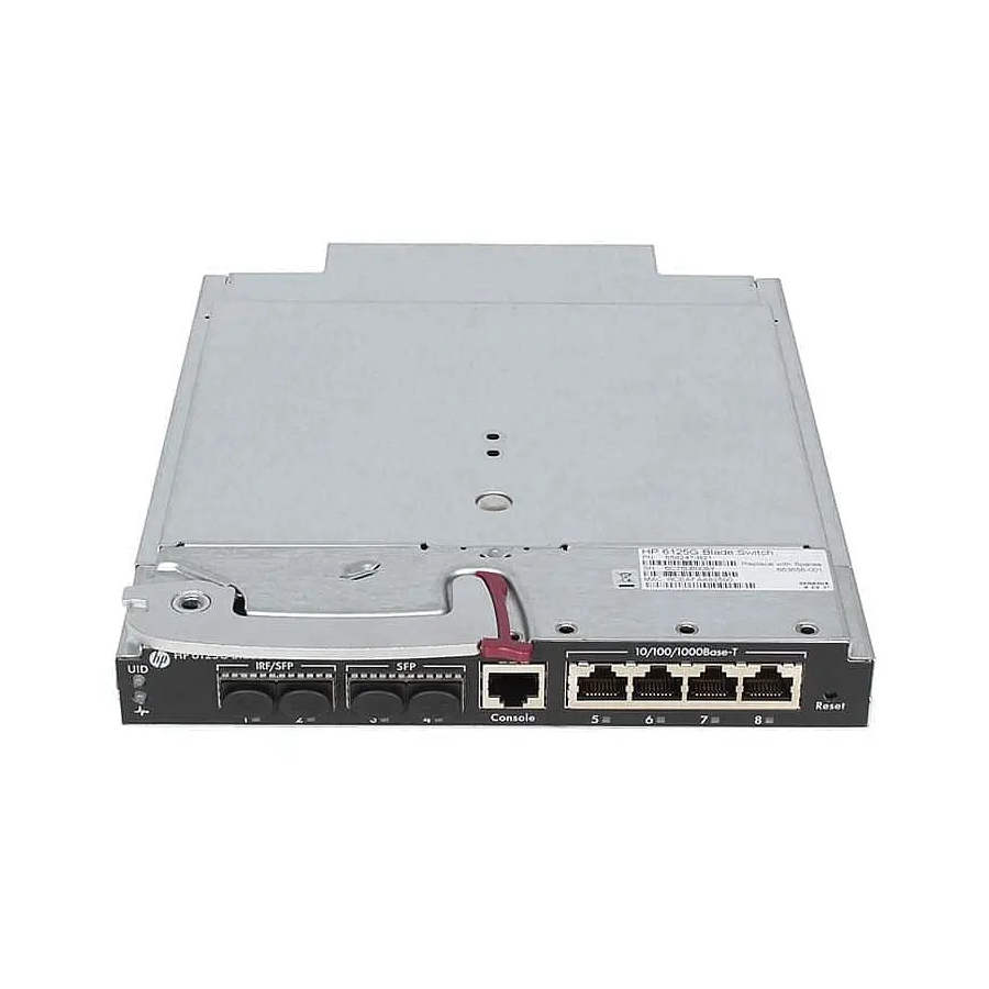
For regulatory identification purposes, the HP 6125 Blade Switch Series are assigned Regulatory Model Numbers (RMN). These regulatory numbers should not be confused with the marketing name HP 6125. Panel views Figure 1 Front panel of the HP 6125G (1) Health LED (2) Unit ID (UID) LED... - Page 6 Figure 2 Front panel of the HP 6125G/XG (1) Health LED (2) Unit ID (UID) LED (3) Ejector lever (4) SFP+ port (5) Release tab (6) 10/100/1000Base-T auto-sensing Ethernet port (7) Reset button (8) 10/100/1000Base-T auto-sensing Ethernet port LED (9) Console port...
-
Page 7: Installing The Blade Switch
Installing the blade switch The HP 6125 switches can be installed into the HP BladeSystem c3000 and c7000 enclosures. The installation position in the enclosure in this document is only for illustration. For more information, see HP BladeSystem Enclosure Setup and Installation Guide . Preparing for installation WARNING! The blade switches are Class 1 laser devices. - Page 8 Figure 3 Opening the ejector lever Slide the blade switch into the interconnect bay (see callout 1 in Figure 4) until it touches the backplane. Push the ejector lever to the closed position. (See callout 2 in Figure Figure 4 Sliding the blade switch into the interconnect bay Verify that the Health LED is green after the blade switch starts up.
-
Page 9: Removing The Blade Switch
Removing the blade switch Wear an ESD-preventive wrist strap and make sure it makes good skin contact and is well grounded. Press the release tab to open the ejector lever. Pull the ejector lever outwards slowly to take out the blade switch. Connecting the blade switch to the network Connecting the blade switch to the network through twisted pair cables... -
Page 10: Testing Connectivity
Figure 5 Using LC optical fiber connectors to connect transceiver modules LC plug SFP module Testing connectivity After you connect the blade switch to the network, use the ping or tracert command to test network connectivity. For more information about these two commands, see HP 6125 Blade Switch Series Network Management and Monitoring Command Reference. -
Page 11: Accessing The Blade Switch For The First Time
Accessing the blade switch for the first time Logging in through the console port The first time you access the blade switch you must use a console cable (see Figure 6) to connect a console terminal, for example, a PC, to the console port on the blade switch. A console cable is an 8-core shielded cable, with a crimped RJ-45 connector at one end for connecting to the console port of the blade switch, and a DB-9 female connector at the other end for connecting to the serial port on the console terminal. -
Page 12: Setting Terminal Parameters
Setting terminal parameters To configure and manage the blade switch, you must run a terminal emulator program on the console terminal, for example, a PC. This section uses Windows XP HyperTerminal as an example. The following are the required terminal settings: •... - Page 13 Figure 9 Setting the serial port used by the HyperTerminal connection Set Bits per second to 9600, Data bits to 8, Parity to None, Stop bits to 1, and Flow control to None, and click OK. Figure 10 Setting the serial port parameters Select File >...
- Page 14 Figure 11 HyperTerminal window On the Settings tab, set the emulation to VT100, and click OK. Figure 12 Setting terminal emulation in Switch Properties dialog box...
-
Page 15: Logging In Through The Oa Module
Press Enter at the prompt. When the command line prompt appears, you can configure the switch. For more information about the configuration, see "Configuring the blade switch." Logging in through the OA module To log in to the blade switch through the HP BladeSystem Onboard Administrator (OA) module: Use a serial cable to connect the terminal (for example, a PC) to the serial port of the OA module. -
Page 16: Configuring The Basic Network Settings
Authentication Characteristics Application scenarios method Username Complex to configure, secure, providing Environments where multiple operators password hierarchical user management cooperate to manage the switch Configuring the basic network settings An HP 6125 blade switch without any configuration can perform basic data forwarding immediately after connecting to a network. - Page 17 # Assign GigabitEthernet 1/1/5 to VLAN 10. [Sysname-vlan10] port gigabitethernet 1/1/5 [Sysname-vlan10] quit...
-
Page 18: Setting Up An Irf Fabric
SFP+ ports to an IRF port for increased bandwidth and availability. When two 6125G or 6125G/XG switches are plugged into adjacent (side-by-side) interconnect bays of the c7000 or c3000, the internal 10-GE cross connect ports between those adjacent 6125G or 6125G/XG can be used for an IRF connection as well. -
Page 19: Identifying Physical Irf Ports On The Member Switches
• available. • Any or all of the four SFP+ ports on the 6125G/XG can be used either for IRF or data connections. Figure 13 IRF fabric in daisy chain topology Figure 14 IRF fabric in ring topology Identifying physical IRF ports on the member switches Identify the physical IRF ports on the member switches according to your topology and connection scheme. -
Page 20: Planning The Cabling Scheme
Planning the cabling scheme Use SFP+ cables or SFP+ transceiver modules and fibers to connect the IRF member switches. SFP+ cables—Reliable and suitable for IRF connection over a relatively short distance. • SFP+ transceiver modules and fibers—More flexible and suitable for IRF connection over a long •... - Page 21 Task Command Display topology information about the IRF display irf topology fabric NOTE: To avoid IP address collision and network problems, configure at least one multi-active detection (MAD) mechanism to detect the presence of multiple identical IRF fabrics and handle collisions. For more HP 6125 Blade Switch Series IRF Configuration Guide information about MAD detection, see...
-
Page 22: Troubleshooting
Troubleshooting Troubleshooting methods When your HP 6125 blade switch fails, you can use the following methods to troubleshoot the blade switch: At the CLI, use the related commands to display the system running information, and locate the • failures. Locate the failures according to the LED status on the blade switch. For more information, see •... -
Page 23: Configuration Problems
Emulation—VT100 • When you modify the settings for the console port of the switch, configure the same settings for the console terminal. Configuration problems At the CLI, you can use related commands to display the blade switch information and locate the failures. When you detect configuration errors, re-configure the blade switch or restore the factory settings for the blade switch. -
Page 24: Bootware Password Loss
NOTE: After rebooted, the blade switch runs with the initial configuration. To restore to the saved configuration, use the display saved-configuration command to display the configuration, and then copy and execute the configuration. BootWare password loss If you forget the BootWare password, contact HP Support. To change the BootWare password, access the Boot menu, enter 5, and change the password as promoted: please input old password: ******... -
Page 25: Hardware Failures
Hardware failures When your blade switch is operating properly, the Health LED is green. If the LED is in other state, failures have occurred. To troubleshoot the failures: Verify that the enclosure is operating properly. Verify that the blade switch is correctly installed. If not, pull out the blade switch and install it again. Press the Reset button on the front panel of the blade switch. -
Page 26: Support And Other Resources
Support and other resources Contacting HP For worldwide technical support information, see the HP support website: http://www.hp.com/support Before contacting HP, collect the following information: Product model names and numbers • • Technical support registration number (if applicable) Product serial numbers •... -
Page 27: Conventions
Conventions This section describes the conventions used in this documentation set. Command conventions Convention Description Boldface Bold text represents commands and keywords that you enter literally as shown. Italic Italic text represents arguments that you replace with actual values. Square brackets enclose syntax choices (keywords or arguments) that are optional. Braces enclose a set of required syntax choices separated by vertical bars, from which { x | y | ... - Page 28 Network topology icons Represents a generic network device, such as a router, switch, or firewall. Represents a routing-capable device, such as a router or Layer 3 switch. Represents a generic switch, such as a Layer 2 or Layer 3 switch, or a router that supports Layer 2 forwarding and other Layer 2 features.
-
Page 29: Appendix A Technical Specifications
Appendix A Technical specifications Table 5 Technical specifications Item HP 6125G HP 6125G/XG Dimensions (H × W × 27.9 × 92.8 × 267.7 mm (1.1 × 3.65 × 27.9 × 92.8 × 267.7 mm (1.1 × 3.65 × 10.54 in) 10.54 in) -
Page 30: Appendix B Ports And Leds
IRF/SFP port and SFP port An HP 6125G has up to four SFP ports. The IRF/SFP ports can be configured for IRF operation, in which case they will operate as SFP+ ports that will accept supported SFP+ modules or cables (see... -
Page 31: Sfp+ Port
SFP+ port An HP 6125G/XG has four SFP+ ports. The SFP+ ports can be configured for IRF operation, in which case they accept supported SFP+ modules or cables. If they are not used for IRF, they accept supported SFP transceiver modules (with the exception of HP X120 1G SFP RJ45 T transceiver), SFP+ modules, or SFP+ cables. - Page 32 Table 9 10 Gbps SFP+ transceiver modules available for the SFP+ ports Multimode Central Fiber fiber modal Product Maximum transmission wavelength Description diameter bandwidth code distance (μm) (nm) (MHz × km) 2000 300 m (984.25 ft) 50/125 82 m (269.03 ft) HP X130 10G JD092B SFP+ LC SR...
-
Page 33: Leds
Figure 15 SFP+ cable (1) Connector (2) Pull latch LEDs Unit ID LED Table 11 Unit ID LED description LED mark Status Description Blue Switch ID selected. Switch ID not selected. Health LED Table 12 Health LED description LED mark Status Description Green... -
Page 34: Sfp Port Led
SFP port LED Table 14 SFP port LED description Port LED status Description The port is operating properly. The port LED fast flashes when the port is sending Steady green or receiving data. No link is present on the port. SFP+ port LED Table 15 SFP+ port LED description Port LED status... -
Page 35: Index
Index A C H I L P R S T Logging in through the console port,7 Logging in through the OA module,1 1 Accessing the IRF fabric to verify the configuration,16 Panel views,1 Configuring basic IRF settings,16 Password loss,19 Configuring the blade switch,1 1 Planning IRF fabric setup,14...