Hoshizaki KML-250MAH Instruction Manual
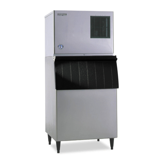
Low-profile modular crescent cuber
Hide thumbs
Also See for KML-250MAH:
- Parts list (33 pages) ,
- Instruction manual (22 pages) ,
- Specification sheet (2 pages)

Related Manuals for Hoshizaki KML-250MAH


Summary of Contents for Hoshizaki KML-250MAH
- Page 1 Hoshizaki Hoshizaki America, Inc. Low-Profile Modular Crescent Cuber Models KML-250MAH, MWH KML-351MAH, MWH KML-451MAH, MWH KML-631MAH, MWH, MRH INSTRUCTION MANUAL “A Superior Degree of Reliability” www.hoshizaki.com Issued: 8-19-2013...
- Page 2 Should the reader have any questions or concerns which have not been satisfactorily addressed, please call, send an e-mail message, or write to the Hoshizaki Technical Support Department for assistance. Phone: 1-800-233-1940; (770) 487-2331 Fax: 1-800-843-1056;...
-
Page 3: Table Of Contents
IMPORTANT This manual should be read carefully before the appliance is installed and operated. Read the warnings and guidelines contained in this manual carefully as they provide essential information for the continued safe use and maintenance of the appliance. Retain this manual for any further reference that may be necessary. CONTENTS Important Safety Information .................... -
Page 4: Important Safety Information
Important Safety Information Throughout this manual, notices appear to bring your attention to situations which could result in death, serious injury, damage to the appliance, or damage to property. WARNING Indicates a hazardous situation which could result in death or serious injury. - Page 5 WARNING, continued • Children should be properly supervised around the appliance. • Do not climb, stand, or hang on the appliance or allow children or animals to do so. Serious injury could occur or the appliance could be damaged. • Do not use combustible spray or place volatile or flammable substances near the appliance.
-
Page 6: Specifications
I. Specifications A. Electrical and Refrigerant Data The rating label and nameplate provide electrical and refrigerant data. The rating label can be seen by removing the front panel. The nameplate is located on the rear panel. For certification marks, see the nameplate. We reserve the right to make changes in specifications and design without prior notice. -
Page 7: Kml-451M_H
20 AMPS 20 AMPS 20 AMPS Ampacity Design Pressure HI-467PSI LO-230PSI HI-427PSI LO-230PSI HI-467PSI LO-230PSI Refrigerant 404A 2 LB. 10.3 OZ. 404A 1 LB. 6.0 OZ. 404A Total Refrigerant Charge with Hoshizaki Remote Condenser Unit URC-9F: 11 LB. 7.4 OZ. -
Page 8: Dimensions/Connections
B. Dimensions/Connections Units: mm [in.] 1. Air-Cooled Models (MAH) Rear Side Model Shown: KML-451MAH KML-250MAH KML-631MAH KML-351MAH Model Shown: KML-451MAH KML-451MAH A 559 [22] 659 [26] Bottom B 515 [20-1/4] 615 [24-1/4] C 505 [19-7/8] 605 [23-7/8] Model Shown: KML-451MAH NOTICE •... -
Page 9: Water-Cooled Models (Mwh)
2. Water-Cooled Models (MWH) Units: mm [in.] Rear Side KML-250/351/451/MWH Model Shown: KML-451MWH KML-250MWH KML-631MWH KML-351MWH Model Shown: KML-451MWH KML-451MWH A 559 [22] 659 [26] Rear KML-631MWH B 515 [20-1/4] 615 [24-1/4] C 505 [19-7/8] 605 [23-7/8] D 403 [15-7/8] 504 [19-7/8] E 55 [2-1/8] NOTICE... -
Page 10: Remote Models (Mrh)
3. Remote Models (MRH) Units: mm [in.] Rear Side Model Shown: KML-631MRH KML-631MRH Model Shown: KML-631MRH A 659 [26] B 615 [24-1/4] Bottom C 605 [23-7/8] D 448 [17-5/8] E 41 [1-5/8] F 63 [2-1/2] G 75 [3] NOTICE Model Shown: KML-631MRH •... -
Page 11: Remote Condenser Unit Urc-9F (Use With Kml-631Mrh)
4. Remote Condenser Unit URC-9F (use with KML-631MRH) Units: mm [in.] NOTICE Allow 24" (61 cm) clearance at front and rear for proper air circulation and ease of maintenance and/or service should they be required. Rear URC-9F Heat of Rejection Icemaker AT 90°F (32°C) Model WT 70°F (21°C) -
Page 12: Installation And Operating Instructions
II. Installation and Operating Instructions WARNING • The appliance must be installed in accordance with applicable national, state, and local codes and regulations. • Failure to install, operate, and maintain the appliance in accordance with this manual will adversely affect safety, performance, component life, and warranty coverage and may result in costly water damage. -
Page 13: How To Remove Panels
• NOTICE! Remote model must be connected to an appropriate remote condenser unit. The remote condenser unit listed below is recommended. Connection to a different remote condenser unit will void the warranty unless Hoshizaki approves a different remote condenser unit for your specific application. For further details, contact your local Hoshizaki distributor. -
Page 14: Setup
(bin accessory) to the bottom of the ice storage bin. 2) Position the dispenser unit/ice storage bin in its permanent location. 3) If required, install an adapter kit or top kit. Contact your local Hoshizaki distributor for recommendations. 4) Level the dispenser unit/ice storage bin in both the left-to-right and front-to-rear directions. - Page 15 Intentionally Left Blank...
-
Page 16: Electrical Connection
E. Electrical Connection WARNING For All Models • Electrical connection must be hard-wired and must meet national, state, and local electrical code requirements. Failure to meet these code requirements could result in death, electric shock, serious injury, fire, or damage. •... - Page 17 KML-250M_H KML-351M_H KML-631M_H KML-451M_H WARNING ELECTRICAL CONNECTION THIS UNIT MUST BE GROUNDED Failure to properly ground or wire this unit could result in death, serious injury, or severe damage to the icemaker. The white lead must be connected to the neutral conductor of the power source. See diagram below.
-
Page 18: Water Supply And Drain Connections
• External filters, strainers, or softeners may be required depending on water quality. Contact your local Hoshizaki Certified Service Representative or local Hoshizaki distributor for recommendations. • A plumbing permit and services of a licensed plumber may be required in some areas. -
Page 19: Icemaker
1. Icemaker Icemaker Water Minimum Icemaker Icemaker Drain Minimum Icemaker Supply Inlet Water Supply Line Size Outlet Drain Line Size 1/2" Female Pipe 1/4" Nominal ID 3/4" Female Pipe 3/4" Nominal Thread (FPT) Copper Water Tubing or Thread (FPT) ID Hard Pipe or Equivalent Equivalent •... -
Page 20: Water-Cooled Condenser
2. Water-Cooled Condenser a) KML-250/351/451MWH (1) Connection to an Open Drain System Condenser Water Minimum Condenser Condenser Drain Minimum Condenser Supply Inlet Water Supply Line Size Outlet Drain Line Size 1/2" Female Pipe 1/4" Nominal ID Copper 3/8" Female Pipe 1/4"... - Page 21 (2) Connection to a Closed Loop System Condenser Water Minimum Condenser Condenser Minimum Condenser Supply Inlet Water Supply Line Size Return Outlet Return Line Size 1/2" Female Pipe 1/4" Nominal ID Copper 3/8" Female Pipe 1/4" Nominal ID Copper Thread (FPT) Water Tubing or Equivalent Thread (FPT) Water Tubing or Equivalent...
-
Page 22: B) Kml-631Mwh
b) KML-631MWH (1) Connection to an Open Drain System Condenser Water Minimum Condenser Condenser Drain Minimum Condenser Supply Inlet Water Supply Line Size Outlet Drain Line Size 1/2" Female Pipe 1/4" Nominal ID Copper 3/8" Female Pipe 1/4" Nominal ID Hard Pipe Thread (FPT) Water Tubing or Equivalent Thread (FPT) - Page 23 (2) Connection to a Closed Loop System Condenser Water Minimum Condenser Condenser Minimum Condenser Supply Inlet Water Supply Line Size Return Outlet Return Line Size 1/2" Female Pipe 1/4" Nominal ID Copper 3/8" Female Pipe 1/4" Nominal ID Copper Thread (FPT) Water Tubing or Equivalent Thread (FPT) Water Tubing or Equivalent...
-
Page 24: Installation Of Remote Condenser Unit
G. Installation of Remote Condenser Unit WARNING • Installation of remote condenser unit must be performed by properly trained and EPA-certified service personnel. • The remote condenser unit must be installed in accordance with applicable national, state, and local codes and regulations. •... -
Page 25: Checks Before Installation
Mixing of refrigerants will result in improper operation and possible damage to the refrigeration system. Line Set Size and Refrigerant Charge Line Set Line Set Greater than 66 Feet (20 m) Hoshizaki Up to 66 Feet (20 m) Maximum 100 Feet (30.5 m) Remote Hoshizaki Condenser... -
Page 26: Line Set Installation
5. Line Set Installation Precharged factory line sets, available as optional equipment from Hoshizaki America, are recommended. For details, see "II.G.5.a) Factory Line Set Installation." Field fabricated line sets are allowed. For details, see "II.G.5.b) Field Fabricated Line Set Installation."... - Page 27 2) Insulate the two copper tubes separately. 3) Install Parker quick connect couplings on each end. OS-QUICK, a universal quick connect coupling kit available as optional equipment from Hoshizaki America, is recommended. NOTICE! Before brazing, remove the Schrader valve core from the access port.
- Page 28 Remote Condenser Unit Icemaker Male Fitting Female Coupling Fig. 12 Discharge Line (Insulated) See "II.G.4 Line Set Size and Refrigerant Charge" for details. Liquid Line (Insulated) See "II.G.4 Line Set Size and Refrigerant Charge" for details. Service Loop DO NOT USE Male Fitting THREAD SEALANT Brush...
-
Page 29: Electrical Connection
6. Electrical Connection WARNING • Electrical connection must meet national, state, and local electrical code requirements. Failure to meet these code requirements could result in death, electric shock, serious injury, fire, or damage. • To reduce the risk of electric shock, make all remote condenser unit connections before connecting the icemaker power supply. -
Page 30: Stacking Remote Condenser Unit
3) Install a ground wire from the icemaker fan motor junction box to the remote condenser unit junction box. Use wire of an appropriate gage and outdoor rating. 4) Install line and neutral wires from the fan motor leads in the icemaker fan motor junction box to the leads in the remote condenser unit junction box. -
Page 31: Final Checklist
H. Final Checklist WARNING CHOKING HAZARD: Ensure all components, fasteners, and thumbscrews are securely in place after installation. Make sure that none have fallen into the dispenser unit/ice storage bin. 1) Is the icemaker level? 2) Is the icemaker in a site where the ambient temperature is within 45°F to 100°F (7°C to 38°C) and the water temperature within 45°F to 90°F (7°C to 32°C) all year around? 3) Is there at least 6"... -
Page 32: Startup
I. Startup WARNING All parts are factory-adjusted. Improper adjustments may adversely affect safety, performance, component life, and warranty coverage. NOTICE • If the icemaker is turned off, wait for at least 3 minutes before restarting the icemaker to prevent damage to the compressor. •... -
Page 33: Maintenance
III. Maintenance The appliance must be maintained in accordance with the instruction manual and labels provided. Consult with your local Hoshizaki Certified Service Representative about maintenance service. WARNING • Only qualified service technicians should service the appliance. • To reduce the risk of electric shock, do not touch the control switch or service switch with damp hands. -
Page 34: Cleaning And Sanitizing Instructions
To prevent damage to the water pump, do not leave the control switch in the "SERVICE" position for extended periods when the water tank is empty. 1. Cleaning Procedure 1) Dilute Hoshizaki "Scale Away" with warm water. Refer to the table. Model Scale Away... -
Page 35: Sanitizing Procedure - Following Cleaning Procedure
9) Pour the cleaning solution into the water tank. 10) Move the service switch to the "WASH" position. 11) Replace the front insulation panel and the front panel in their correct positions. 12) Turn on the power supply to start the washing process. 13) Turn off the power supply after 30 minutes. - Page 36 4) Move the service switch to the "WASH" position. 5) Replace the front insulation panel and the front panel in their correct positions. 6) Turn on the power supply to start the sanitizing process. 7) Turn off the power supply after 15 minutes. 8) Remove the front panel.
-
Page 37: Preparing The Icemaker For Periods Of Non-Use
IV. Preparing the Icemaker for Periods of Non-Use NOTICE • When storing the icemaker for an extended time or in sub-freezing temperatures, follow the instructions below to prevent damage. • To prevent damage to the water pump, do not leave the control switch in the "SERVICE"... - Page 38 3) Open the condenser water supply line drain valve. If connected to a closed loop system, also open the condenser return line drain valve. 4) Attach a compressed air or carbon dioxide supply to the condenser water supply line drain valve. 5) Open the water regulating valve by using a screwdriver to pry up on the spring retainer underneath the spring.
-
Page 39: Disposal
V. Disposal The appliance contains refrigerant and must be disposed of in accordance with applicable national, state, and local codes and regulations. Refrigerant must be recovered by properly certified service personnel. - Page 40 HOSHIZAKI AMERICA, INC. 618 Hwy. 74 S., Peachtree City, GA 30269 USA TEL (770) 487-2331 FAX (770) 487-3360 www.hoshizaki.com 1A3085-010...