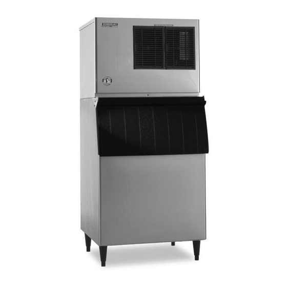
Hoshizaki KML-451MAH Service Manual
Low-profile modular crescent cuber
Hide thumbs
Also See for KML-451MAH:
- Parts list (26 pages) ,
- Instruction manual (24 pages) ,
- Specifications (2 pages)

Related Manuals for Hoshizaki KML-451MAH


Summary of Contents for Hoshizaki KML-451MAH
- Page 1 Hoshizaki Hoshizaki America, Inc. Low-Profile Modular Crescent Cuber Models KML-451MAH KML-451MWH SERVICE MANUAL “A Superior Degree of Reliability” www.hoshizaki.com ™ Number: 73143 Issued: 3-1-2007...
- Page 2 HOSHIZAKI provides this manual primarily to assist qualified service technicians in the service and maintenance of the unit. Should the reader have any questions or concerns which have not been satisfactorily addressed, please call, write or send an e-mail message to the HOSHIZAKI Technical Support Department for assistance. HOSHIZAKI AMERICA, INC.
-
Page 3: Table Of Contents
This manual should be made available to the technician prior to service or maintenance. CONTENTS I. Specifications ........................5 A. Icemaker ........................5 1. KML-451MAH (air-cooled) ..................5 2. KML-451MWH (water-cooled) ................. 6 II. General Information ......................7 A. Construction ........................7 1. KML-451MAH (air-cooled) ..................7 2. - Page 4 A. Water Circuit and Refrigeration Circuit ................ 20 1. KML-451MAH (air-cooled) ..................20 2. KML-451MWH (water-cooled) ................21 B. Wiring Diagrams ......................22 1. KML-451MAH (air-cooled) and KML-451MWH (water-cooled) ......22 C. Performance Data ....................... 23 1. KML-451MAH (air-cooled) ..................23 2. KML-451MWH (water-cooled) ................24 IV.
-
Page 5: Specifications
I. Specifications A. Icemaker 1. KML-451MAH (air-cooled) AC SUPPLY VOLTAGE 115/60/1 AMPERAGE 10.3 A ( 5 Min. Freeze AT 104°F / WT 80°F) MINIMUM CIRCUIT AMPACITY 20 A MAXIMUM FUSE SIZE 20 A APPROXIMATE ICE PRODUCTION Ambient WATER TEMP. (°F) PER 24 HR. -
Page 6: Kml-451Mwh (Water-Cooled)
2. KML-451MWH (water-cooled) AC SUPPLY VOLTAGE 115/60/1 AMPERAGE 8.9 A ( 5 Min. Freeze AT 104°F / WT 80°F) MINIMUM CIRCUIT AMPACITY 20 A MAXIMUM FUSE SIZE 20 A APPROXIMATE ICE PRODUCTION Ambient WATER TEMP. (°F) PER 24 HR. Temp.(°F) lbs./day ( kg/day ) *404 (183) 402 (182) -
Page 7: General Information
II. General Information A. Construction 1. KML-451MAH (air-cooled) Water Supply Condenser Inlet Fan Motor Spray Tubes Drain Valve Wash Valve Junction Box Inlet Water Valve Condenser Control Box Water Pump Drier Float Switch Expansion Valve Hot Gas Valve Control Compressor... -
Page 8: Kml-451Mwh (Water-Cooled)
2. KML-451MWH (water-cooled) Water Supply Inlet Water Spray Tubes Regulator Drain Valve Wash Valve Junction Box Inlet Water Valve Condenser Water Pump Control Box Drier Float Switch Expansion Valve Hot Gas Valve Control Compressor Switches Bin Control Thermostat... -
Page 9: Sequence Of Operation
B. Sequence of Operation The steps in the sequence are as outlined below. When power is supplied, a 5 second delay occurs at startup. Note that the order of the LEDs from the outer edge of the board is 1, 4, 3, 2. 1. -
Page 11: Control Board
C. Control Board • A HOSHIZAKI exclusive solid-state control is employed in KML-451MAH and KML-451MWH Modular Crescent Cubers. • All models are pretested and factory-adjusted. CAUTION 1. Fragile, handle very carefully. 2. A control board contains integrated circuits, which are susceptible to failure due to static discharge. -
Page 12: Control Board Layout
1. Control Board Layout Control Products "E" Control Board Output Test Switch (used to test relays on board) Dip Switch Alarm Reset Switch Backup Freeze Timer LED Connector K3 Harvest Control (thermistor) Backup Harvest Connector K4 Timer LED Open (not connected) Alarm Buzzer Microprocessor Power LED... -
Page 13: Features
2. Features a) Maximum Water Supply Period – 6 minutes Inlet water valve opening, in the harvest cycle, is limited by the harvest timer. The water valve cannot remain open longer than the maximum period. The water valve can close in less than six minutes if the harvest cycle is completed. -
Page 14: F) Led Lights And Audible Alarm Safeties
f) LED Lights and Audible Alarm Safeties The red LED indicates proper control voltage and will remain on unless a control voltage problem occurs. At startup a 5 second delay occurs while the board conducts an internal timer check. A short beep occurs when the power switch is turned OFF. The green LEDs 1 through 4 energize and sequence from initial startup as listed in the table below. -
Page 15: Controls And Adjustments
However, a setting longer than the factory setting may be advised in cases where the flush provided at harvest needs to be prolonged for extra cleaning. Before changing this setting, call the HOSHIZAKI Technical Support Department at 1-800-233-1940 for recommendations. Keep in mind that setting the harvest timer to a longer setting will decrease 24 hour production. -
Page 16: C) Pump-Out Timer (Dip Switch 3 & 4)
c) Pump-Out Timer (dip switch 3 & 4) When a freeze cycle is completed, the pump motor stops, and the icemaker resumes operation in 2 seconds. Then, during cycles when a pump out is called for, the pump motor drains the water tank for the time determined by the pump-out timer. The pump- out timer also acts in place of the harvest timer during cycles with a pump out. -
Page 17: E) Freeze Timer (Dip Switch 9 & 10)
e) Freeze Timer (dip switch 9 & 10) CAUTION Adjust to proper specification, or the unit may not operate correctly. The freeze timer setting determines the maximum allowed freeze time to prevent possible freeze-up issues. Upon termination of freeze timer, machine initiates the harvest cycle. -
Page 18: Harvest Control - Thermistor
D. Harvest Control – Thermistor A thermistor (semiconductor) is used for a harvest control sensor. The resistance varies depending on the suction line temperatures. The thermistor detects the temperature of the evaporator outlet to start the harvest timer. No adjustment is required. If necessary, check for resistance between thermistor leads, and visually check the thermistor mounting, located on the suction line next to the evaporator outlet. -
Page 19: Service Switch
2. Service Switch When the control switch is in the "SERVICE" position, the control switch supplies power to the service switch and the machine is in service mode. The service switch has three positions: "DRAIN," "CIRCULATE," and "WASH." See the information below for details of each function. -
Page 20: Technical Information
III. Technical Information A. Water Circuit and Refrigeration Circuit 1. KML-451MAH (air-cooled) -
Page 21: Kml-451Mwh (Water-Cooled)
2. KML-451MWH (water-cooled) -
Page 22: Wiring Diagrams
B. Wiring Diagrams 1. KML-451MAH (air-cooled) and KML-451MWH (water-cooled) -
Page 23: Performance Data
C. Performance Data 1. KML-451MAH (air-cooled) APPROXIMATE ICE WATER TEMP. (ºF/ºC) AMBIENT TEMP. PRODUCTION PER 24 HR. (ºF/ºC) 50/10 70/21 90/32 70/21 80/27 90/32 lbs./day kg./day 100/38 APPROXIMATE ELECTRIC 70/21 CONSUMPTION 80/27 90/32 watts 100/38 1020 APPROXIMATE WATER 70/21 0.43 0.38... -
Page 24: Kml-451Mwh (Water-Cooled)
2. KML-451MWH (water-cooled) APPROXIMATE ICE WATER TEMP. (ºF/ºC) AMBIENT TEMP. PRODUCTION PER 24 HR. (ºF/ºC) 50/10 70/21 90/32 70/21 80/27 90/32 lbs./day kg./day 100/38 APPROXIMATE ELECTRIC 70/21 CONSUMPTION 80/27 90/32 watts 100/38 APPROXIMATE WATER 70/21 1.68 1.88 2.80 CONSUMPTION PER 24 HR. 80/27 1.84 2.15... -
Page 25: Service Diagnosis
IV. Service Diagnosis A. 10-Minute Diagnostic Procedure The 10 minute check out procedure is basically a sequence check which can be used at unit start-up or for system diagnosis. Using this check out procedure will allow you to diagnose electrical system and component failures in approximately 10 minutes under normal operating conditions of 70°F or warmer air and 50°F or warmer water temperatures. -
Page 26: Diagnostic Charts
the board. Note: Normal freeze cycle will last 20 to 40 minutes depending on model and conditions. Cycle times and pressures should follow performance data provided in this manual. 6) Pump-Out Cycle (10/20 second pump out) – the compressor remains energized, the hot gas valve energizes, the fan motor de-energizes, the pump motor stops for 2 seconds. - Page 27 Problem Possible Cause Remedy [1] The icemaker will not e) High Pressure Control 3. Ambient or condenser 3. Reduce temperature. start. (continued) (continued) water temperature too warm. 4. Refrigerant 4. Recharge. overcharged. 5. Fan not operating. 5. See chart 1.[6] (except water-cooled model) 6.
- Page 28 Problem Possible Cause Remedy [1] The icemaker will not m)Control Switch 1. SERVICE position. 1. Move to ICE position. start. (continued) 2. Bad contacts. 2. Check and replace. [2] Water continues to a) Float Switch 1. Connector 1. Place in position. be supplied, and the disconnected.
- Page 29 Problem Possible Cause Remedy [5] No water comes from d) Pump Motor 3. Wiring to pump motor. 3. Check for loose spray tubes. Water (continued) connection or open, and pump will not start, or replace. freeze cycle time is 4. Defective capacitor. 4.
-
Page 30: Evaporator Is Frozen Up
2. Evaporator is Frozen Up Problem Possible Cause Remedy [1]Freeze cycle time is a) Float Switch 1. Leads short-circuit or 1. Check and replace. too long. defective switch. 2. Float does not move 2. Clean or replace. freely. b) Inlet Water Valve 1. -
Page 31: Low Ice Production
Problem Possible Cause Remedy [3]Other (continued) g) Water Supply Line 1. Too small; requires 1. Increase water line size. 3/8" OD line dedicated per machine. h) Water Filter 1. Flow rate too small. 1. Replace with filter that has larger flow rate. 3. - Page 32 Problem Possible Cause Remedy [2] Abnormal noise. c) Compressor 2. Mounting pad out of 2. Reinstall. (continued) (continued) position. d) Refrigerant Lines 1. Rub or touch other 1. Replace. lines or surfaces. [3] Ice in storage bin a) Drain Line(s) 1.
-
Page 33: Removal And Replacement Of Components
V. Removal and Replacement of Components IMPORTANT 1. Ensure all components, fasteners and thumbscrews are securely in place after the equipment is serviced. 2. The Polyol Ester (POE) oils used in R-404A units can absorb moisture quickly. Therefore it is important to prevent moisture from entering the system when replacing or servicing parts. -
Page 34: Evacuation And Recharge (R-404A)
Remember to loosen the connection, and purge the air from the hose. For air- cooled and water-cooled models, see the nameplate for the required refrigerant charge. For remote air-cooled models, see the rating label inside the icemaker. Hoshizaki recommends only virgin refrigerant or reclaimed refrigerant which meets ARI Standard No. -
Page 35: Removal And Replacement Of Compressor
B. Removal and Replacement of Compressor IMPORTANT Always install a new drier every time the sealed refrigeration system is opened. Do not replace the drier until after all other repair or replacement has been made. Note: When replacing a compressor with a defective winding, be sure to install the new start capacitor and start relay supplied with the replacement compressor. -
Page 36: Removal And Replacement Of Expansion Valve
C. Removal and Replacement of Expansion Valve IMPORTANT Sometimes moisture in the refrigeration circuit exceeds the drier capacity and freezes up at the expansion valve. Always install a new drier every time the sealed refrigeration system is opened. Do not replace the drier until after all other repair or replacement has been made. -
Page 37: Removal And Replacement Of Evaporator
1) Turn off the power supply. 2) Remove the panels. 3) Recover the refrigerant and store it in an approved container. 4) Remove the screw and the solenoid. 5) Disconnect the valve. If replacing the hot gas valve, also remove the strainer. 6) Place the new valve and strainer, if applicable, in position. -
Page 38: Removal And Replacement Of Water Regulating Valve - Water Cooled Model Only
8) Remove the drier, then place the new drier in position. 9) Braze all fittings while purging with nitrogen gas flowing at a pressure of 3 to 4 PSIG. 10) Check for leaks using nitrogen gas (140 PSIG) and soap bubbles. 11) Evacuate the system, and charge it with refrigerant. -
Page 39: Adjustment Of Water Regulating Valve - Water-Cooled Model Only
G. Adjustment of Water Regulating Valve - Water-Cooled Model Only The water regulating valve (also called "water regulator") is factory-adjusted. No adjustment is required under normal use. Adjust the water regulator, if necessary, using the following procedures. 1) Prepare a thermometer to check the condenser drain temperature. Attach a pressure gauge to the high-side line of the system. -
Page 40: Removal And Replacement Of Thermistor
7) Braze the fittings while purging with nitrogen gas flowing at a pressure of 3 to 4 PSIG. CAUTION Always protect the headmaster body by using a damp cloth to prevent it from overheating. Do not braze with the headmaster body exceeding 250°F (121°C). 8) Remove the drier in the icemaker, then place the new drier in position. -
Page 41: Removal And Replacement Of Fan Motor
9) Attach the new thermistor to the suction pipe in the same position as the previous thermistor. Be very careful to prevent damage to the leads. Secure it using the thermistor holder and recommended foam insulation. 10) Secure the insulation using the plastic cable ties. 11) Connect the thermistor leads through the bushing of the control box to the K3 connector on the control board. -
Page 42: Removal And Replacement Of Pump Motor
L. Removal and Replacement of Pump Motor 1) Turn off the power supply. 2) Remove the front panel. 3) Remove the three screws and the float switch assembly. 4) Remove the wiring connectors from the pump motor leads. 5) Disconnect the hoses attached to the pump motor assembly. 6) Remove the four screws and the pump motor. -
Page 43: Cleaning And Maintenance Instructions
1. Cleaning Procedure 1) Dilute approximately 10.5 fl. oz. (310 ml) of Hoshizaki "Scale Away" with 2 gallons (7.6 l) of warm water. 2) Remove all ice from the evaporator and the storage bin. -
Page 44: Sanitizing Procedure - Following Cleaning Procedure
15) Move the service switch to the "DRAIN" position. 16) Replace the front panel in its correct position and turn on the power supply for 2 minutes. 17) Turn off the power supply and remove the front panel. 18) Move the control switch to the "ICE" position. 19) Replace the front panel in its correct position. -
Page 45: Maintenance
12) Remove the front panel. 13) Repeat steps 18 through 31 in "1. Cleaning Procedure" two times to rinse thoroughly. 14) Move the control switch to the "ICE" position. 15) Replace the front panel in its correct position. 16) Clean the storage bin with water. 17) Turn on the power supply, and start the automatic icemaking process. - Page 46 1. On water-cooled model only, first remove the water from the water-cooled condenser: 1) Turn off the power supply. 2) Remove the front panel. 3) Move the control switch on the control box to the "OFF" position. 4) Wait 3 minutes. 5) Move the control switch to the "ICE"...
- Page 47 V-1 and Later OFF OFF OFF OFF OFF OFF ON OFF OFF ON KML-351MWH ON OFF ON ON OFF OFF OFF OFF OFF ON KML-451MAH B-1 and Later OFF OFF OFF OFF OFF OFF OFF OFF OFF ON KML-451MWH B-1 and Later...
- Page 48 B. Wiring Diagram 1. KML-451MAH and KML-451MWH B-1 and Later...