
Related Manuals for GE GSS20 Series


Summary of Contents for GE GSS20 Series
- Page 1 GE Consumer Home Services Training TECHNICAL SERVICE GUIDE General Electric Side-by-Side Knob Control/Metal Liner Refrigerator MODEL SERIES: GSS20 GSS22 GSS25 ESS22 ESS25 HSS22 HSS25 SSS25 PUB # 31-9071 02/01...
- Page 2 If grounding wires, screws, straps, clips, nuts, or washers used to complete a path to ground are removed for service, they must be returned to their original position and properly fastened. GE Consumer Home Services Training Technical Service Guide Copyright © 2001 All rights reserved.
-
Page 3: Table Of Contents
T T T T T able of Contents able of Contents able of Contents able of Contents able of Contents Introduction Introduction Introduction Introduction Introduction ........ -
Page 4: Introduction
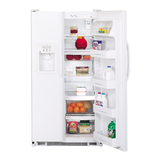
Introduction 2001 Energy SxS models are being introduced in The freezer has adjustable shelves, slide-out Spillproof shelf, QuickSpace shelf, and deep door response to the requirement for more energy- efficient refrigerators by mid year 2001, along with shelves, based on model. The fresh food section having feature and operation enhancements. -
Page 5: Installation
Installation ATTENTION INSTALLER: FOR A QUALITY INSTALLATION, FOLLOW THESE INSTRUCTIONS. RAISE DO NOT 9 IS COLDEST ROLLERS @@@@@ PPPPP @@@@@ PPPPP @@@@@ PPPPP @@@@@ PPPPP @@@@@ PPPPP @@@@@ PPPPP @@@@@ PPPPP @@@@@ PPPPP @@@@@ PPPPP @@@@@ PPPPP @@@@@ PPPPP @@@@@ PPPPP @@@@@ PPPPP... -
Page 6: Specifications
Specifications – 4 –... -
Page 7: Nomenclature
H = HOTPOINT T = TROPICAL D = DELUXE WIRE D = CUBED ICE / WATER AA = ALMOND/ALMOND P = PROFILE (GE) G = GLOBAL I = DELUXE GLASS E = CUBED & CRUSHED ICE / WATER BB = BLACK/BLACK... - Page 8 Warranty Information Sales slip or cancelled check is required as proof of original purchase date to obtain service under warranty. Note: Water filter cartridge warranty is 30 days. All warranty service is provided by our Factory Service Centers or an authorized Customer Care® technician.
- Page 9 Operating Characteristics Table of Contents Normal Operating Characteristics That Are Different from Previous Models . . Abnormal Operating Characteristics (Incorrect Operation) ....Adaptive Defrost ..........Cooling Operation (Adaptive Defrost) .
-
Page 10: Normal Operating Characteristics That Are Different From Previous Models
Normal Operating Characteristics That Are • Length of time the compressor has run since Different from Previous Models the last defrost cycle. • Amount of time the defrost heaters were on in • Icemaker auger rotates clockwise. the last defrost cycle. •... -
Page 11: Defrost Heater Operation (Adaptive Defrost)
into a continuous cool mode (pre-chill). During pre- Liner Protection Mode chill, the freezer temperature may be driven below The liner protection mode will activate if either of the set point. However, the fresh food temperature the doors have been open for 3 minutes. This will be regulated by the damper. -
Page 12: Dispenser Lock
Dispenser Lock Hinge System and Door Closure When the dispenser system is locked, no dispenser command will be accepted. This includes the dispenser cradle and will prevent accidental dispensing that may be caused by children or pets. If a pad is pressed with the system locked, it will be acknowledged with 3 Cam with pulses of the LOCK LED accompanied by an... -
Page 13: Airflow (Cabinet Interior)
Airflow (Cabinet Interior) “Jelly Roll” Condenser The freezer compartment is designed so that when the evaporator fan is operating, air is drawn into the bottom of the air tunnel and through the evaporator. The cold air is then pushed out into the top of the freezer. -
Page 14: Main Control Board
Main Control Board THERMISTOR MODEL DAMPER ENCODER COMMUNICATION COILS SELECT INPUTS INPUTS INPUT/OUTPUT INPUTS ACCUMULATED FF AND FRZ DOOR OPENINGS (MINUTES) FAN OUTPUTS COMPRESSOR RUN TIME (MINUTES) DEFROST HEATER ON TIME (MINUTES) PROCESSING UNIT OUTPUTS COOLING PRE-CHILL DEFROST COMPRESSOR DOOR DEFROST SWITCH OUTPUTS... -
Page 15: General Locator Views
General Locator Views Temperature Temperature Tech Data Sheet Tech Data Sheet Controls Controls Location Location Freezer Light Freezer Light Switch Switch Fresh Food Fresh Food Light Switch Light Switch Damper Damper Fresh Food Fresh Food Evaporator Evaporator Thermistor Thermistor Evaporator Evaporator Thermistor Thermistor... - Page 16 Main Main Control Control Board Board Condenser Condenser Jelly Roll Jelly Roll Condenser Condenser Compressor Compressor Water Water Water Solenoids Solenoids GEA00917 Capacitor Capacitor Overload Overload Overload and Relay and Relay (under cover) (under cover) – 14 –...
-
Page 17: Mechanical Disassembly
Mechanical Disassembly Table of Contents Door Gasket ............17 Door Handles . - Page 18 Fresh Food Thermistor ..........24 Door Dispenser Control Panel .
-
Page 19: Door Gasket
Door Gasket The rear flange of the gasket is positioned between the inner and outer door panels. The screws under the gasket flap must be loosened. 1. Remove the door bins. 2. Loosen 40 screws located under the door gasket. 3. -
Page 20: Fresh Food Door Adjustment
Cam with Thimble Screw Cam Riser Hinge Adjustment Hinge GEA00909 3. Remove the base grille. 9. Remove the screw, hinge cam, and thimble 4. Disconnect the water supply tube. To from the bottom of the door. disconnect the tube, push in the white collar on 10. -
Page 21: Fresh Food Light
2. Disconnect the connectors for the door light switch and temperature control switches. Connectors Connectors Encoder Encoder Board Board Freezer Door Light Switch GEA00870 The freezer door light switch is located on the left 3. Disconnect the connectors for the light and of the freezer compartment. -
Page 22: Shelves
2. On models without a replacement LED, apply The QuickSpace shelf splits in half and slides the year and month sticker to the new under itself to allow for storage of tall items on the cartridge. shelf below. To adjust this shelf: 3. -
Page 23: Door Shelf Extenders
Freezer Light The freezer light is attached to the evaporator fan housing. 1. Remove the light cover by lifting it off the tabs. 2. Replace the appliance light bulb. GEA00874 Icemaker The icemaker is located in the rear of the freezer compartment. -
Page 24: Ice Dispenser Drive
Ice Dispenser Drive Mounting Screws Mounting Screws Mounting Screws The ice dispenser drive turns the ice dispenser auger in either crushed or cube mode. 1. Remove 2 Phillips screws from the ice dispenser drive. 2. Slide the dispenser out until the cable connector is visible. -
Page 25: Defrost Heater And Freezer Thermistor
4. Remove 4 Phillips screws from the evaporator Defrost Heater and Freezer Thermistor cover. The defrost heater warms the evaporator during 5. Remove the evaporator cover. the defrost mode of operation. The freezer thermistor, located at the bottom left side of the 6. -
Page 26: Overtemperature Thermostat And Evaporator Thermistor
Overtemperature Thermostat and Door Dispenser Control Panel Evaporator Thermistor The door dispenser control panel allows the consumer to select water, crushed ice, or ice The main control board monitors the resistance of cubes. It is an interface to the main control board. the evaporator thermistor. -
Page 27: Ice Crusher
3. Turn over the ice bucket and ice dispenser cover. Remove the Phillips screw. 4. Remove the cover. 5. Remove the Phillips screw for the ice cube control linkage and slide the linkage to the rear of the ice bucket. 4. -
Page 28: Ice Cube Solenoid
2. Remove 2 Phillips mounting screws. 6. Disconnect the wire connectors. 3. Pull out the motor. 4. Disconnect the wire connectors. Solenoid Solenoid Solenoid 5. Remove the drive fork and nut. Solenoid Mounting Screws Solenoid Mounting Screws Motor Motor Ground Ground Ground Mounting... -
Page 29: Condenser Fan
4. Remove 2 screws from the condenser fan cover. Screws Screws 5. Pull out the fan until the electrical connector is exposed. 6. Disconnect the electrical connector. GEA00894 5. With a file, score the capillary tube just above the soldered section. Break off the soldered section of the capillary tube. -
Page 30: Main Control Board
IMPORTANT: To ensure proper door closure, the Main Control Board refrigerator rollers must be adjusted to level the The main control board is located in the back of refrigerator. This is different from previous models. the unit. This board controls the operation of the unit. -
Page 31: Fresh Food Air Damper
Cable Cable Connector Connector GEA00900 4. Remove 2 Phillips screws from the solenoid connection. 5. Disconnect the water tube and remove the solenoid. Fresh Food Air Damper The fresh food air damper is located in the upper left corner of the fresh food compartment. The damper opens to allow cold air to circulate from the freezer to the fresh food compartment. - Page 32 Notes – 30 –...
- Page 33 Notes – 31 –...
-
Page 34: Diagnostics
Diagnostics Table of Contents Efficient Use of Diagnostics ......... 32 Failure Causes (Table 1) . -
Page 35: Failure Causes (Table 1)
t s i t s i t s i u l i u l i u l i c t i u l i y t l c t i u l i y t l y t l y t l u l i ) t i ) t i... -
Page 36: Main Control Board (Low-Voltage Side)
Main Control Board (Low-Voltage Side) (Sample only, check schematic shipped with product) 1 - Tan 1 - Not Used 2 - 13VDC Red 2 - Yel / Blu Band 3 - Blk-DC Common 3 - Wht / Blu Band 4 - Violet 4 - Brn 5 - Wht 5 - 5VDC Blu / Wht... -
Page 37: Main Control Board (120 Vac Side)
Main Control Board (120 VAC Side) PROCESSING UNIT OUTPUTS COOLING PRE-CHILL DEFROST COMPRESSOR DOOR DEFROST SWITCH OUTPUTS INPUTS 1 - Blk / Wht 2 - Violet / Blk 3 - Yel 4 - Gry 5 - Not Used 6 - Violet 7 - Red 8 - Blk 9 - Orn... -
Page 38: Main Control Board Locator Table (Low-Voltage Side)
– 36 –... - Page 39 – 37 –...
-
Page 40: Main Control Board Locator Table (120 Vac Side)
* When activated – 38 –... -
Page 41: Fresh Food Warm - Freezer Warm (Diagnostic Chart)
Fresh Food Warm - Freezer Warm – 39 –... -
Page 42: Freezer Warm - Fresh Food Normal (Diagnostic Chart)
Freezer Warm - Fresh Food Normal – 40 –... -
Page 43: Fresh Food Warm - Freezer Normal (Diagnostic Chart)
Fresh Food Warm - Freezer Normal – 41 –... -
Page 44: Fresh Food Too Cold - Freezer Normal (Diagnostic Chart)
Fresh Food Too Cold - Freezer Normal – 42 –... -
Page 45: Refrigerator Dead - No Sound, No Cooling (Diagnostic Chart)
Refrigerator Dead, No Sound, No Cooling – 43 –... -
Page 46: Evaporator Fan Not Running (Diagnostic Chart)
Evaporator Fan Not Running – 44 –... -
Page 47: Condenser Fan Not Running (Diagnostic Chart)
Condenser Fan Not Running – 45 –... -
Page 48: Damper Door Not Operating (Diagnostic Chart)
Damper Door Not Operating – 46 –... -
Page 49: Compressor Not Running (Diagnostic Chart)
Compressor Not Running – 47 –... -
Page 50: Heavy Frost On Evaporator (Diagnostic Chart)
Heavy Frost on Evaporator – 48 –... - Page 51 NOTE: The thermistor’s resistance has a negative coefficient. As the temperature increases, the thermistor’s resistance decreases. – 49 –...
-
Page 52: Component And Connector Locator Views
Component and Connector Locator Views Evaporator Evaporator Light Light Evaporator Evaporator Defrost Defrost Thermistor Thermistor Thermistor Thermostat Thermostat Thermostat Evaporator Evaporator Defrost Defrost Heater Heater Freezer Freezer Thermistor Thermistor Thermistor GEA00916 – 50 –... - Page 53 Fresh Food Fresh Food Light Switch Light Switch Damper Damper Fresh Food Fresh Food Thermistor Thermistor Fresh Food Fresh Food Lights Lights GEA00913 – 51 –...
- Page 54 Main Main Control Control Board Board Condenser Condenser Jelly Roll Jelly Roll Condenser Condenser Compressor Compressor Water Water Water Solenoids Solenoids GEA00917 Capacitor Capacitor Overload Overload Overload and Relay and Relay (under cover) (under cover) – 52 –...
- Page 55 Main Control Board (120 VAC Side) PROCESSING UNIT OUTPUTS COOLING PRE-CHILL DEFROST COMPRESSOR DOOR DEFROST SWITCH OUTPUTS INPUTS 1 - Blk / Wht 2 - Violet / Blk 3 - Yel 4 - Gry 5 - Not Used 6 - Violet 7 - Red 8 - Blk 9 - Orn...
-
Page 56: Schematics
Schematics FREEZER DOOR Ω Ω Ω Ω Ω Ω Ω Ω Ω Ω – 54 –... - Page 57 – 55 –...
- Page 58 Low Voltage DC 120 VAC – 56 –...
- Page 59 Notes – 57 –...
-
Page 60: Illustrated Parts Catalog
Illustrated Parts Catalog – 58 –... - Page 61 – 59 –...
- Page 62 – 60 –...
- Page 63 – 61 –...
- Page 64 – 62 –...
- Page 65 – 63 –...
- Page 66 – 64 –...
- Page 67 – 65 –...
- Page 68 – 66 –...
- Page 69 – 67 –...
- Page 70 – 68 –...