Table of Contents
Advertisement
Quick Links
Advertisement
Table of Contents

Related Manuals for Bosch LTC 4600 Series


Summary of Contents for Bosch LTC 4600 Series
- Page 1 LTC 4600 Series Instruction Manual Fiber Optic Transmission System...
-
Page 2: Important Safeguards
EN | 2 LTC 4600 Series | Instruction Manual | Important Safeguards 10. Power d d isconnect - Units with or without Important Safeguards ON/OFF switches have power supplied to the unit whenever the power cord is inserted into Read, follow, and retain for future reference all of the power source;... -
Page 3: Safety Precautions
EN | 3 LTC 4600 Series | Instruction Manual | Safety Precautions 15. Safety c c heck - Safety checks should be disconnect device for switching off the voltage to performed upon completion of service or repairs the unit. to the unit to ensure proper operating condition. - Page 4 EN | 4 LTC 4600 Series | Instruction Manual | FCC & ICES Information Your Bosch product was developed and Moving - Disconnect the power before moving manufactured with high-quality material the unit. Move the unit with care. Excessive and components that can be recycled and force or shock may damage the unit and the reused.
-
Page 5: Fcc Information
EN | 5 LTC 4600 Series | Instruction Manual | Safety Precautions Disclaimer NOTICE! This device is intended for use in Underwriter Laboratories Inc. (“UL ”) has not tested the public areas only. U.S. federal law strictly performance or reliability of the security or signaling prohibits surreptitious recording of oral aspects of this product. -
Page 6: Table Of Contents
LTC 4671 Series Modules for System4/Allegiantfi Keyboard Transmission ....14 LTC 4651 Series Modules for Bosch Biphase Control Code or RS-232 Transmission ..15 LTC 4637 Series Rack-mount Card Cage . -
Page 7: Unpacking
A list of available models is shown below. Complete The shipping carton is the safest container in which the specifications can be found on the LTC 4600 Series unit may be transported. Save it for possible future use. Data Sheet that can be downloaded from www.boschsecuritysystems.com. -
Page 8: Installation
EN | 8 LTC 4600 Series | Instruction Manual | Installation 4.2 Installing Stand-alone Modules INSTALLATION 1. Choose an appropriate flat surface where the 4.1 Installing Rack-mount Modules stand-alone module can be conveniently mounted, 1. Install the LTC 4637 Series card cage unit as then mark the locations of the keyhole slots on the described in a later section of this document. -
Page 9: Ltc 4641, Ltc 4642 Series Modules For Video Transmission
EN | 9 LTC 4600 Series | Instruction Manual | Installation 4.3 LTC 4641, LTC 4642 Series Modules for Video Transmission 4.3.1 Indicators / Operation 1. The POWER LED illuminates when AC power is applied to the unit. 2. LTC 4642/60 and LTC 4642/50 units: The Video Out / AGC LED illuminates GREEN when a video signal is being received, or RED if a video signal is not present. -
Page 10: Ltc 4744, Ltc 4745 Series Modules For Simultaneous 4-Channel Video Transmission
EN | 10 LTC 4600 Series | Instruction Manual | Installation 4.4 LTC 4744, LTC 4745 Series Modules 3. LTC 4744/60, LTC 4744/50, and LTC 4744/00 units: The respective CAMERA ON LED for Simultaneous 4-Channel Video illuminates when a video signal is connected to its Transmission input. -
Page 11: Ltc 4630, Ltc 4631 Series Modules For Bilinx
EN | 11 LTC 4600 Series | Instruction Manual | Installation 4.5 LTC 4630, LTC 4631, Series Modules 4.5.2 Indicators / Operation 1. The POWER LED illuminates when AC power for Bilinx Video/Data Transmissions is applied to the unit. 4.5.1 Important Considerations 2. -
Page 12: Ltc 4628, Ltc 4629 Series Modules For Video + Bosch Biphase Control Code Transmission
EN | 12 LTC 4600 Series | Instruction Manual | Installation 4.6 LTC 4628, LTC 4629 Series Modules for Video + Bosch Biphase Control Code Transmission 4.6.1 Indicators / Operation 1. The POWER LED illuminates when AC power is applied to the unit. - Page 13 EN | 13 LTC 4600 Series | Instruction Manual | Chapter Bosch Security Systems | 10 October 2003...
-
Page 14: Ltc 4671 Series Modules For System4/Allegiantfi Keyboard Transmission
EN | 14 LTC 4600 Series | Instruction Manual | Installation LTC 4671 Series Modules for A termination resistor is typically NOT required when a module is connected to the following controller System4 / Allegiant Keyboard devices: Transmission Allegiant LTC 8500 Series main CPU bays •... -
Page 15: Ltc 4651 Series Modules For Bosch Biphase Control Code Or Rs-232 Transmission
EN | 15 LTC 4600 Series | Instruction Manual | Installation 4.8 LTC 4651 Series Modules for Bosch Biphase Control Code or RS-232 Transmission 4.8.1 Indicators / Operation 1. The POWER LED will light when AC power is applied to the unit. -
Page 16: Ltc 4637 Series Rack-Mount Card Cage
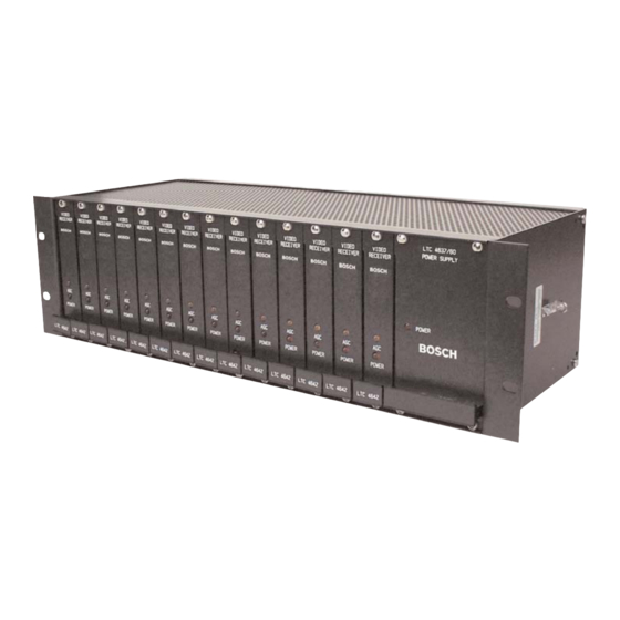
EN | 16 LTC 4600 Series | Instruction Manual | Replacement Parts LTC 4637 Series Rack-mount 4.9.3 LTC 4637 Maintenance / Service Information Card Cage 1. The power supply is fused with a 1A slow blow 4.9.1 Installation fuse. To replace the fuse, remove the AC power 1. -
Page 17: Troubleshooting
EN | 17 LTC 4600 Series | Instruction Manual | Troubleshooting TROUBLESHOOTING Video Links: Video Problems Verify that a valid video signal is being applied to the transmitter module. Verify the integrity of the coax connections between devices and fiber modules. -
Page 18: Dimensional Outlines
EN | 18 LTC 4600 Series | Instruction Manual | Dimensional Outlines DIMENSIONAL OUTLINES LTC 4641 VIDEO TX +9-12VDC 25.4 1.19 Figure 12 Stand-alone Modules: LTC 4641/60, LTC 4641/50 3.06 Figure 13 Stand-alone Modules: LTC 4642/50, LTC 4642/60, LTC 4651/60, LTC 4651/50... - Page 19 EN | 19 LTC 4600 Series | Instruction Manual | Dimensional Outlines 4.45 LTC 4xxx 1 LTC 4637 Rack Width Figure 14 Stand-alone Modules: LTC 4744/50, Figure 16 Rack-mount Modules: LTC 4600/00, LTC 4744/60, LTC 4671/60, LTC 4671/50, LTC 4642/00, LTC 4651/00, LTC 4671/00,...
- Page 20 Telephone+1 888-289-0096 Fax: +31 40 2577 330 Fax: +65 6319 3499 +1 585-223-9180 emea.securitysystems@bosch.com apr.securitysystems@bosch.com Email: security.sales@us.bosch.com www.boschsecurity.com www.boschsecurity.com www.boschsecurity.us © 2008 Bosch Security Systems, Inc. F01U087540 08-28 | Updated July 08, 2008 | Data subject to change without notice.