Table of Contents

Related Manuals for Ariston ACO 32 RFFI SYSTEM


Summary of Contents for Ariston ACO 32 RFFI SYSTEM
-
Page 1: Installation And Servicing
Installation and Servicing Instructions SERIES Type C Boilers ACO 27 MFFI G.C.N: 47-116-34 ACO 32 MFFI G.C.N: 47-116-35 ACO 27 RFFI G.C.N: 41-116-09 ACO 32 RFFI G.C.N: 41-116-10 LEAVE THESE INSTRUCTIONS WITH THE END USER Country of destination: GB/IE... -
Page 2: Table Of Contents
TABLE OF CONTENTS GENERAL INFORMATION MAINTENANCE 1.1. 6.1. ENERAL NFORMATION ENERAL EMARKS 1.2. 6.2. ECHNICAL NFORMATION LEANING THE RIMARY XCHANGER 1.3. 6.3. VERALL LEANING THE ONDENSATE 6.4. PERATIONAL INSTALLATION SERVICING INSTRUCTIONS 2.1. EFERENCE TANDARDS 2.2. 7.1. ITING THE PPLIANCE EPLACEMENT OF ARTS 2.3. -
Page 3: General Information
1. GENERAL INFORMATION 1.1. ENERAL NFORMATION This manual is an integral and essential part of the product. It Read the instructions and recommendations in these Installation should be kept with the appliance so that it can be consulted by and Servicing Instructions carefully to ensure proper installation, the user and our authorised personnel. -
Page 4: Technical
1.2. ECHNICAL NFORMATION Name ACO 27 MFFI (COMBI) ACO 27 RFFI (SYSTEM) CE Certification 0085BP0229 0085BP0229 Flue Type Heat Input max (Domestic Hot Water) 30.0 ----------- Heat Input max/min (Central Heating) 25.5 / 8.9 25.5 / 8.9 Heat Output max (Domestic Hot Water) 27.0... - Page 5 Name ACO 32 MFFI (COMBI) ACO 32 RFFI (SYSTEM) CE Certification 0085BP0229 0085BP0229 Flue Type Heat Input max (Domestic Hot Water) 32.0 ----------- Heat Input max/min (Central Heating) 31.6 /10.5 31.6 /10.5 Heat Output max (Domestic Hot Water) 32.0 ----------- Heat Output max/min (Central Heating) 28 / 9.5 28 / 9.5...
-
Page 6: Overall View
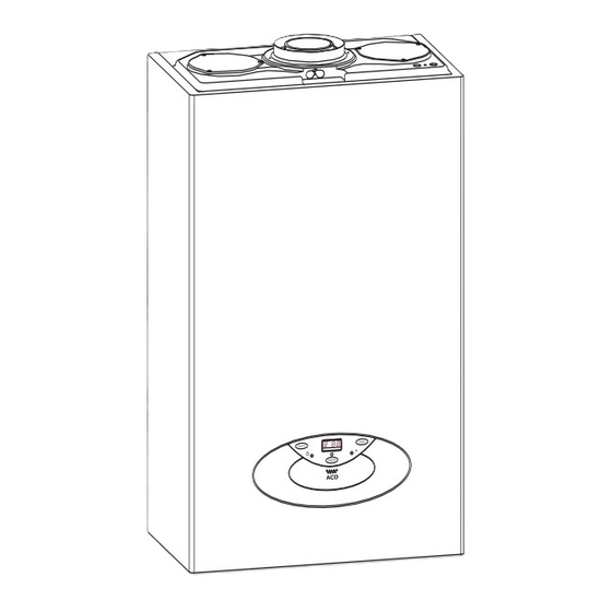
1.3. VERALL 27/32 RFFI (SYSTEM) 27/32 MFFI (COMBI) 14 15 12 13 14 15 . 1.0 EGEND Flue connector Mixer Spark generator Burner Ignition and detection electrode Air release valve Main heat exchanger (aluminium) Central Heating flow temperature probe 10. Automatic by-pass 11. -
Page 7: Installation
2. INSTALLATION 2.2. ITING THE PPLIANCE The appliance may be installed in any room or indoor area, although particular attention is drawn to the requirements of the 2.1. EFERENCE TANDARDS current I.E.E. Wiring Regulations, and in Scotland, the electrical provisions of the Building Regulations applicable in Scotland, with respect to the installation of the combined appliance in a The technical information and instructions provided herein below room containing a bath or shower, the location of the boiler in a... -
Page 8: Overall
2.3. VERALL IMENSIONS 27/32 RFFI (SYSTEM) . 2.1 . 2.0 2.4. MINIMUM CLEARANCES EGEND A = Central Heating Flow (3/4”) (22mm Copper Tail) B = Domestic Hot Water Outlet (1/2”) (15 mm Copper Tail) In order to allow access to the interior of the boiler for maintenance C = Gas Inlet (3/4”) ( 22mm Copper Tail) purposes, the boiler must be installed in compliance with the clearance requirements indicated in the diagram below. -
Page 9: Mounting The 2.6. Electrical
2.5. M Note: The diagrams for the electrical system are indicated in OUNTING THE PPLIANCE Sections 2.12 and 2.13. After removing the boiler from its packaging, remove the Warning, this appliance must be earthed. template from the separate box containing the connection kit. : Pay particular attention to any test water that may spill External wiring to the appliance must be carried out by a from the appliance. - Page 10 2.8. ATER ONNECTIONS IEW OF THE OILER ONNECTIONS Legend: 27/32 MFFI (COMBI) A = Central Heating Flow B = Domestic Hot Water Outlet C = Gas Inlet D = Domestic Cold Water Inlet E = Central Heating Return H = Condensate discharge I = Safety valve discharge J = Drain valve Central Heating...
- Page 11 The discharge pipe must be terminated in a suitable position: must be used for pipe work carrying drinking water, a scale i) Connecting in to an internal soil stack (at least 450 mm reducer should also be used to reduce the risk of scale above the invert of the stack).
- Page 12 2. External termination of condensate drainage pipe via ATER REATMENT internal discharge branch (e.g. sink waste) and condensate The boiler is equipped with an aluminium alloy main heat siphon exchanger. The detailed recommendations for water treatment are given in BS 7593:1992 (Treatment of water in domestic hot water central heating systems);...
- Page 13 2.9. YSTEM ONNECTING THE The provision for satisfactory flue termination must be made as described in BS 5440-1. The appliance must be installed so that the flue terminal is MPORTANT exposed to outdoor air. BEFORE CONNECTING THE FLUE ENSURE THAT LITRE OF The terminal must not discharge into another room or space WATER HAS BEEN POURED INTO THE EXHAUST CONNECTION TO...
-
Page 14: Orizontal )
Warning Important The exhaust gas ducts must not be in contact with or close to Ensure that the flue is not blocked. inflammable material and must not pass through building Ensure that the flue is supported and structures or walls made of inflammable material. assembled in accordance with these When replacing an old appliance, the flue system must be instructions. -
Page 15: (Ø 80 / 125 Horizontal/Vertical)
Clamp Screws Seal Fig. 2.12 Should the flue require extending, the flue connections are push fit, however, one flue bracket should be used to secure each metre of flue. 2.9.2 F 5” F ITTING THE (Ø 80 / 125 H EE PAGE FOR MAXIMUM AND MINIMUM FLUE RUNS ORIZONTAL... -
Page 16: Ertical )
EE PAGE FOR MAXIMUM AND MINIMUM FLUE RUNS 2.9.3. F ITTING THE OAXIAL (Ø 60 / 100 V ERTICAL ONTENTS (60mm) ILICONE (60/100mm) ONICAL DAPTOR (80/125mm) ERTICAL CREWS The vertical flue kit is supplied with a specially designed weather proof terminal fitted, it can be used either with a flat roof or a pitched roof. -
Page 17: (Ø80 / 80)
EE PAGE FOR MAXIMUM AND MINIMUM FLUE RUNS 2.9.4. F (Ø80 / 80) ITTING THE Where it is not possible to terminate the flue within the distance permitted for coaxial flues, the twin flue pipe can be used by fitting a special adaptor to the flue connector and using the aperture for the air intake located on top of the combustion chamber. - Page 18 Fig. 2.18 In the event that the air intake and exhaust are run to the left, it will be necessary to reduce the height of the air intake by cutting 20mm from the base of the air intake elbow (see Fig. 2.18) In the event that twin flue pipes are used, and the boiler has a side clearance of less than 60mm from the wall, it is necessary to cut a larger diameter hole for the flue...
- Page 19 For coaxial systems, the maximum development value, mentioned in the table below also takes into account an elbow. For twin flue systems the maximum development value, mentioned in the table includes the exhaust gas/air intake terminal. Type 5 outlets should respect the following instructions: 1- Use the same ø...
-
Page 20: Control Panel
Fig. 2.21 RAWINGS ARE INDICATIVE OF FLUEING OPTIONS ONLY 2.10. ITTING THE ECHANICAL IGITAL LOCK The ACO MFFI (Combi) boiler is supplied with a factory fitted mechanical time clock. There is a digital clock available as an optional extra (code: 706348). To fit the digital clock it is necessary to proceed as follows:- 1. - Page 21 The ACO RFFI (System) boiler is not supplied with a clock, however a mechanical and digital clock is available as an optional extra (mechanical - code: 706349 and digital - code: 706348) To fit the clock it is necessary to proceed as follows:- 1.
-
Page 22: Clock
2.11. ETTING THE ECHANICAL LOCK 1. General layout The mechanical clock covers a 24 hour period. Each tappet represents 15 minutes A (Fig. 2.30). An override switch is located on the clock B (Fig 2.30). 2. To set the time To set the time of day, grasp the outer edge of the dial and turn slowly clockwise until the correct time is lined up with the arrow C (Fig. - Page 23 Changing the programmed switching times Press the “Prog” key repeatedly until the switching time you want Automatic Manual Continuous Operation Operation Operation to change is displayed. You can now enter the new data. See point “Entering the switching times”. = ON = ON = Continuously ON Notes on storing switching times:...
-
Page 24: Onnection
2.12. CCESSORY ONNECTION IMPORTANT!! Before carrying out any repairs to the appliance always ensure that the external power supply has been isolated. The boiler will remain live even when the ON/OFF knob is in the “O”(off) position. In order to gain access to the external control connections, it is first necessary to remove the casing (as shown in Section 3.2) then proceed as follows: 1. - Page 25 FITTING THE EXTERNAL SENSOR The exter nal sensor is supplied with the interface PCB (Fig. 2.33). The external sensor should be sited no more than 50 m from the boiler and on an external north facing wall, between 2 and 2.5 metres above the ground.
- Page 26 2.13. The P.C.B. is fitted with 2 fuses, on the live and the LECTRICAL IAGRAM neutral. The fuse holder contains: - 5 x 20mm “3.15A Slow” glass fuses TIMER FUSE FUSE . 2.31...
- Page 27 Legend: CN1 = Start of coil (black) End of coil (brown) - ON/OFF button “Hall” sensor power supply 12V (red) - Green LED (Indicates burner on) “Hall” sensor input (white) - COMFORT button “Hall” sensor neutral (blue) - Programming key + Not used - Central Heating temperature adjustment - Menu button...
-
Page 28: Ircuit Diagram
2.14. W ATER IRCUIT IAGRAM 27/32 MFFI (Combi) . 2.32 EGEND 14 - Domestic hot water flow switch Burner 15 - Motorised valve Ignition/detection electrode 16 - Automatic By-pass Air release valve 17 - Circulation pump with automatic Main heat exchanger air release valve Central heating flow temperature probe 18 -... - Page 29 27/32 RFFI (System) . 2.33 14 - Expansion vessel EGEND 15 - Central heating return temperature probe Burner 16 - Air pressure switch Ignition/detection electrode Air release valve Central Heating Flow Main heat exchanger Gas Inlet Central heating flow temperature probe Central Heating Return Condensate Trap Gas valve...
- Page 30 3. COMMISSIONING 3.1. NITIAL REPARATION MTS (GB) Limited support the initiative. In Sections 11 and 12 of this manual you will find the commissioning checklist (page 78) and the service interval record (Page 79), It is important the commissioning checklist is completed in the presence of your customer, they are shown how to use it, and it is signed by them.
- Page 31 off and flush through cold, fill the central heating system again, add a flushing detergent, we highly recommend the use of a flushing detergent appropriate for the metals used in the aluminium alloy circuit. These include (Fernox Superfloc, BetzDearborn Sentinel X300 or X400), whose function is to dissolve any foreign matter that may be in the system, and run the boiler on central heating until it reaches its operating temperature, flush the system as instructed by the...
-
Page 32: Asing
3.2. To remove the front casing panel, follow these steps: EMOVING THE ASING Remove the screws “A” (F 3.1); Remove the four screws from case hooks (two at the top and two at the bottom) and rotate anti-clockwise (F 3.2); Lift and unhook the case panel (F 3.3). - Page 33 3.3. ONTROL ANEL 27/32 MFFI (Combi) . 3.4 Description Button Description Green LED ON/OFF Switch (illuminated = burner on) “COMFORT” Function Push-button Time clock Reset Button/ Selector knob for Summer/Winter Flue Test**/ scroll through Functions Menu Central Heating Temperature Adjustment Knob Menu Switch Control Panel Cover Programming “+”...
- Page 34 27/32 RFFI (System) . 3.4 Description Button Description Green LED ON/OFF Switch (illuminated = burner on) Not used Time clock (Optional Extra) Reset Button/ Central Heating Temperature Adjustment Knob Flue Test**/ scroll through Functions Menu Menu Switch Control Panel Cover Programming “+”...
- Page 35 3.4. 1. Make sure that: NITIAL TART the cap of the automatic air release valve is loosened; the system pressure is at least 1 bar on the pressure gauge “F” (Fig. 3.4); the gas cock is closed (Fig. 3.7); the electrical connection has been carried out in the correct manner.
-
Page 36: Shown During
3.5. During operation of the boiler, while it is carrying out its normal ISPLAY ESSAGES HOWN URING operations, the left-hand display shows a series of characters that ORMAL PERATION refer to the operations indicated below: No request for heat Heating Pump overrun for heating Domestic hot water Pump overrun for domestic hot water... -
Page 37: Arameters
6 6 0 0 (ACO 27 MFFI - RFFI ) Soft light from 0 0 to 9 9 9 9 4 4 3 3 (ACO 32 MFFI - RFFI ) as % of maximum Heating Power (NG) - Page 38 left-hand display right-hand display Function factory setting 0 0 1 1 Standard selects low temperature systems from 0 0 0 0 to 0 0 1 1 0 0 0 0 Low Temperature or standard systems Temperature regulation controlled by from 9 9 0 0 to 9 9 1 1 9 9 0 0 external sensor p p 6 6...
- Page 39 Maximum Heating Power adjustment 2 2 The maximum heating power can be adjusted between the maximum power allowed by the boiler (22.5kW - ACO 27 and 28kW - ACO 32) and the minimum recommended power (10kW - ACO 27 and 13kW - ACO 32) indicated in the graph below (Parameter 2 = 20%).
- Page 40 Boiler types Factory setting: 00 - ACO 27 / 32 MFFI (COMBI) 02 - ACO 27 / 32 RFFI (SYSTEM) HIS PARAMETER MUST NEVER BE ADJUSTED Secondary outlet Function E E (This parameter can be modified only with the interface PCB connected) With the interface PCB connected, it is possible to set the boiler to operate with one of the following accessories, (see Section 2.12 for further information).
- Page 41 ETTING THE EMPERATURE IELD Using the programming keys it is possible to make the following adjustments: “0 0 0 0 ” signifies that the flow temperature (which may be set by means of the knob on the front control panel) may be regulated from 20 to 75°C.
- Page 42 P P 5 5 ETTING THE URVE NCLINE (Only enabled when an outdoor sensor is installed) When using an outdoor sensor, the microprocessor-controlled P.C.B. calculates the most suitable flow temperature, taking into account the exter nal temperature and the type of system. The microprocessor is capable of doing this because it is possible to establish a link between the external temperature and the flow temperature of the Central Heating system water.
- Page 43 to press the keys together, two dashes appear at the top of the right-hand display (see Fig. 3.29). This function is disabled by pressing the reset key . b - by pressing the key, the boiler is forced to operate at minimum power, two dashes appear at the bottom of the right- hand display (Fig.
-
Page 44: Gas Regulation Check
3.6.3 G Supply pressure check AS REGULATION CHECK 1. Loosen screw “1” (Fig. 3.33) and connect the pressure gauge connection pipe into the test point. 2. Turn the boiler on at maximum power, enabling the “flue sweep” function (press the key for 5 seconds and then press the programming keys together ensuring the dashes are... -
Page 45: Adjustment
(normally the bath tap), adjust the cold water inlet valve until the correct temperature rise is achieved at the stated flow rate (ACO 27 MFFI - D T=35°C @ 10.8 l/min and ACO 32 MFFI - D T=35°C @ 13.1 l/min. -
Page 46: Systems
3.10 The boiler is protected from malfunctioning by means of internal OILER AFETY YSTEMS checks by the P.C.B., which brings the boiler to a stop if necessary. In the event of the boiler being shut off in this manner, a code appears on the display which refers to the type of shut-off and the reason behind it. -
Page 47: C Ompletion
AILY In order to prevent sticking components, the boiler carries out a self- diagnosing test every 21 hours: the pump runs for 15 seconds and the diverter valve moves once. FROST EVICE The anti-frost function acts on the central heating flow temperature probe, independently from other regulations, when the electrical supply is turned on. - Page 48 4. ZONE VALVES The boiler can be connected to a central heating system that uses two zone valves allow connection to an indirect storage cylinder. There are two possible types of wiring diagram, one for the connection to an Unvented Cylinder (Diagram. A, page 49) and one for connection to an open vented cylinder (Diagram B, page 50).
- Page 49 IRING IAGRAM FOR ONNECTION TO AN RISTON NVENTED YLINDER IAGRAM...
- Page 50 IRING IAGRAM FOR ONNECTION TO AN ENTED YLINDER IAGRAM...
-
Page 51: Central Heating Mode
5. SEQUENCE OF OPERATION ENTRAL EATING MODE Activation of the time clock and/or room thermostat starts the boiler. The letter C is shown in the display followed by the flow temperature. With the boiler in rest, the diverter valve is in the domestic hot water position, activation of the central heating changes the position of the motorised valve head, moving the diverter valve into the central heating position. -
Page 52: Maintenance
6. MAINTENANCE To ensure the validity of the 5 Year Guarantee, the boiler must be serviced annually by a CORGI registered gas engineer. 6.1. ENERAL EMARKS Provided the boiler was registered within the terms stated on the guarantee card, MTS (GB) Limited will write to the householder as IMPORTANT!! the boiler becomes due for it’s annual service. -
Page 53: Servicing Instructions
To ensure efficient safe operation, the boiler must be serviced SERVICING INSTRUCTIONS annually by a competent person. Before starting any servicing work, ensure both the gas and electrical supplies to the boiler are isolated and the boiler is cool. Before and after servicing, a combustion analysis should be made via the flue sampling point (please refer to 3.6.3). -
Page 54: Access To Thec
7.3. . 7.4 CCESS TO THE OMBUSTION HAMBER 7.3.1. R EMOVING THE 1. Disconnect the electrical connector “C” (F . 7.5); 2. Disconnect the compensation tube “D” (F . 7.5); 3. Remove the clip “E” (F . 7.6). 4. Unscrew the four screws “F” (F . -
Page 55: Air
7.3.2. R 7.3.3. R EMOVING THE RESSURE WITCH EMOVING THE URNER 1. Disconnect the electrical connector “G” (F . 7.9); With the fan removed (see Section 7.3.1); 2. Disconnect the compensation tube “H” (F . 7.9); 1. Remove the four allen screws “J” (F . -
Page 56: Heat
7.3.4. R 7.3.5. R EMOVING THE LECTRODES EMOVING THE XCHANGER 1. Remove the two allen screws “K”, pulling off the ignition IMPORTANT!! cable (F . 7.14); Every time that the combustion chamber cover or the 3. Extract the electrodes (F . - Page 57 . 7.18 . 7.22 . 7.23 . 7.19 . 7.20 . 7.24 . 7.21...
-
Page 58: Trap ( Tube )
7.3.6. R 7.3.7. R EMOVING THE ONDENSATE TUBE EMOVING THE ONDENSATE 1. Open the clamp “Q” and remove the condensate trap 1. Remove the condensate trap tube (see section 7.3.6); connection pipe (F . 7.25); 2. Unscrew the screw “S” (F . -
Page 59: Alve
7.4.1. R EMOVING THE ALVE CCESS TO THE ALVE 1. Disconnect the electrical connection “V” from the gas 1. Remove the casing and lower the control panel as valve (F . 7.31); instructed in Section 7.1. 2. Release the top nut “W” (F . -
Page 60: Water
7.4.2. R EMOVING THE SPARK GENERATOR CCESS TO THE ATER IRCUIT 1. Disconnect the electrical connection “Y” from the spark Important! Before any component is removed, the boiler generator (F . 7.34); must be drained of all water. 2. Remove the screws “Z” from the bottom of the spark generator (F . -
Page 61: Safety
7.5.2. R 7.5.3. R EMOVING THE AFETY ALVE EMOVING THE UTOMATIC 1. Remove the U-clip “A2” (Fig. 7.39); 1. Remove the U-clip “A3” (F . 7.41); 2. Remove the valve (Fig. 7.40). 2. Unscrew valve (F . 7.42); 3. Remove (F . -
Page 62: Actuator
7.5.4. R EMOVING THE IVERTER ALVE CTUATOR 1. Unplug the electrical connector “A4” (F . 7.44); 2. Release the retaining clip “A5” and remove the diverter valve actuator (F . 7.45). . 7.47 7.5.6. R EMOVING THE 1. Unplug the electrical connection “A7” (F . -
Page 63: Ressure Gauge
7.5.7. R EMOVING THE RESSURE AUGE 1. Release U-clip “B1” (F . 7.51 - 7.52); 2. Ease the pressure gauge through the control panel from the rear; 3. Remove the pressure gauge. (F 7.53). . 7.50 . 7.51 . 7.52 . -
Page 64: Xpansion Vessel
7.5.8. R EMOVING THE XPANSION ESSEL 1. Unscrew the screws “B2” (F . 7.54); 2. Loosen nut “B3” (F . 7.55); 3. Unscrew the screw “B4” (F . 7.56); 3. Remove the expansion vessel (F . 7.57). . 7.54 . 7.57 7.5.9 R D.H.W. -
Page 65: (N.t.c.)
7.5.10. Removing the C.H. Flow Temperature 7.5.11. R C.H. R EMOVING THE ETURN EMPERATURE Probe (N.T.C.) (N.T.C.) ROBE 1. Unscrew the two screws “B7” (Fig. 7.60); 1. Unscrew the two screws “B8” (Fig. 7.62); 2. Remove the electrical connection from the C.H. flow 2. - Page 66 7.6.2. R P.C.B. EMOVING THE CCESS TO THE ONTROL YSTEM 1. Remove the inspection cover of the PCB box (F 7.6.1. C HECKING THE USES 7.66); 2. Unplug all the electrical connections (F . 7.67); 1. Remove the inspection cover of the PCB box (F 3.
-
Page 67: Clock
7.6.3. R EMOVING THE LOCK 1. Open the control panel (see the paragraph “Removing the P.C.B.s”); 2. Unplug the electrical connection from the time clock and unscrew the four screws (F . 7.73); 3. Remove the time clock (F . 7.74). . - Page 68 FAULT FINDING 8.1. It is possible to detect and correct defects by using the standard fault finding AULT INDING UIDE diagrams described in this chapter. CHARTS HESE CHECKS ARE NOT EXHAUSTIVE Model 27/32 MFFI...
- Page 69 Model 27/32 RFFI SYSTEM...
- Page 72 27/32 (MFFI) SHORT SPARE PART LIST 61 60 58 57 56 55 RESET ON/OFF CONFOR cod. 65102191 RESET ON/OFF CONFOR...
- Page 73 G.C. part ARISTON Description Part. No. Flue restrictor 65102197 Spark generator 65102177 Main P.C.B. 65102236 Secondary heat exchanger (27 kW) 990685 Secondary heat exchanger (32 kW) 6510356 Temperature probe (DHW) 998458 Safety valve (3bar) 65103222 Pressure gauge 65102220 Gas valve...
- Page 74 27/32 RFFI (SYSTEM) 59 58 56 55 54 53 RESET ON/OFF code 65102299 RESET ON/OFF...
- Page 75 G.C. part ARISTON Description Part. No. Flue restrictor 65102196 Spark generator 65102177 Main P.C.B. 65102236 Safety valve (3bar) 65103222 Pressure gauge 65102220 Gas valve 65102247 Pump 65102902 Automatic air vent 995865 Expansion vessel 995940 Air pressure switch 65102232 Hose clip...
- Page 76 ANNUAL MAINTENANCE CHECKLIST To ensure that the five year guarantee applies, the following checks must be carried out once a year and the service history completed in the Service Interval Record (Section 12, page 79) by a CORGI registered engineer: Visually check the appliance for correct installation;...
- Page 78 BENCHMARK COMMISSIONING CHECKLIST...
- Page 79 SERVICE INTERVAL RECORD...
- Page 80 ERMS AND ONDITIONS OF UARANTEE Please read these terms and conditions which are in manufacturer’s guarantee has been withdrawn. addition to any terms and conditions detailed in this book On the 12 month anniversar y of the appliance or any registration card supplied with your appliance. installation, you must have it serviced to continue any guarantee offered into the following year.