Table of Contents
Advertisement
Quick Links
SAFETY CONSIDERATIONS
Read and follow manufacturer instructions carefully. Fol-
low all local electrical codes during installation. All wiring
must conform to local and national electrical codes. Improper
wiring or installation may damage thermostat.
Recognize safety information. This is the safety alert sym-
bol
. When the safety alert symbol is present on equipment
or in the instruction manual, be alert to the potential for person-
al injury.
Understand the signal words DANGER, WARNING, and
CAUTION. These words are used with the safety alert symbol.
DANGER identifies the most serious hazards which will result
in severe personal injury or death. WARNING signifies a haz-
ard which could result in personal injury or death. CAUTION
is used to identify unsafe practices which would result in minor
personal injury or property damage.
GENERAL
The fan coil programmable thermostats are wall-mounted
or unit-mounted, low-voltage thermostats which maintain
room temperature by controlling the operation of a fan coil
unit. Separate heating and cooling set points, auto-changeover
capability, 2 or 4-pipe configurability, and single or dual set
point options allow for greater flexibility.
All thermostats allow up to 4 time/temperature settings to
be programmed per 24-hour period. Each thermostat stores
programs for 7 independent days. Batteries are not required.
During power interruption the internal NEVERLOST™ mem-
ory stores configuration settings for an unlimited time while
the clock continues to run for at least 48 hours.
The thermostat can be configured to accept several different
equipment configurations, including 2 or 4 pipe operation.
The temperature display range of the thermostat is 35 to
99 F (2 to 36 C).
NOTE: The thermostat is factory-configured for use in 4-pipe
applications. The advanced setup must be performed to config-
ure the thermostat for use with 2-pipe applications.
OPERATION
Thermostat Display —
ed in the center of the thermostat. See Fig. 1. The following
information can be displayed on the screen:
• time
• day of week
• mode (OFF, HEAT, COOL, Program On, or AUTO)
• fan setting (auto, low, medium, or high)
• room temperature
• desired temperature
• setup indicator
• lock indicator
• programming indicators
• schedule indicators
• outside sensor indicator
Manufacturer reserves the right to discontinue, or change at any time, specifications or designs without notice and without incurring obligations.
PC 111
Book 1
4
Tab
11a 13a
Owner's Manual
Part Number 33CSSP2-FC
The thermostat display is locat-
Catalog No. 533-30004
Printed in U.S.A.
Programmable Thermostat
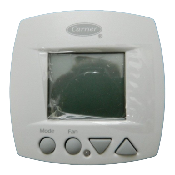
Heat or Cool Indicator —
located on the bottom middle cover of the thermostat. See
Fig. 2. The light will be red if the thermostat is in Heating
mode. The light will be green if the thermostat is in Cooling
mode.
Thermostat Front Panel Buttons —
stat has buttons on the front cover which are used to raise or
lower the desired set point and change the current mode. See
Fig. 2.
SET POINT BUTTONS — The UP ARROW and DOWN
ARROW buttons will raise or lower the current desired tem-
perature set point.
Fig. 1 — Thermostat Display
Mo
BACK LIT
LIQUID
CRYSTAL
DISPLAY
FAN
MODE
HEAT/COOL INDICATOR
BUTTON
BUTTON
RED = HEAT
GREEN = COOL
Fig. 2 — Thermostat Front Panel Buttons
Form 33CS-18SO
Pg 1
33CS
Fan Coil
A Heat or Cool indicator is
The thermo-
Am
COOL
AUTO
HEAT
UP AND DOWN
ARROW BUTTONS
6-03
Replaces: 33CS-15SO
Advertisement
Table of Contents

Related Manuals for Carrier 33CSSP2-FC


Summary of Contents for Carrier 33CSSP2-FC
-
Page 1: Programmable Thermostat
33CS Fan Coil Programmable Thermostat Owner’s Manual Part Number 33CSSP2-FC SAFETY CONSIDERATIONS Heat or Cool Indicator — A Heat or Cool indicator is located on the bottom middle cover of the thermostat. See Read and follow manufacturer instructions carefully. Fol- Fig. - Page 2 FAN BUTTON — The fan button determines fan operation. Press the DOWN ARROW button again to display OF. The fan can be set to Auto, Off, Low, Medium, or High. Press the Mode button to continue. MODE BUTTON — The Mode button selects the operating 5.
- Page 3 Table 1 — Daily Schedule Planner SCHEDULE OF THE Occupied 1 Occupied 2 Occupied 3 Unoccupied WEEK Start / Stop / Heat / Cool Start / Stop / Heat / Cool Start / Stop / Heat / Cool Heat / Cool Monday Tuesday Wednesday...
- Page 4 Single Set Point Operation — Heating to Cooling mode and Cooling to Heating mode when When the thermostat required. The thermostat will automatically switch to maintain is configured for single set point operation, the display on the the desired temperature setting. The thermostat does not need thermostat will change.
- Page 8 Copyright 2003 Carrier Corporation Manufacturer reserves the right to discontinue, or change at any time, specifications or designs without notice and without incurring obligations. Book 1 PC 111 Catalog No. 533-30004 Printed in U.S.A. Form 33CS-18SO Pg 8 6-03 Replaces: 33CS-15SO...