
Related Manuals for Garmin PERSONAL NAVIGATOR GPS 95 XL


Summary of Contents for Garmin PERSONAL NAVIGATOR GPS 95 XL
- Page 1 GPS 95 XL PERSONAL NAVIGATOR OWNER'S MANUAL KMCI TYGER STAT AUTO YZ-- KCOU...
- Page 4 Afterwards, try a trip of your own to realize the value of the GPS 95 as your Personal Navigator our Product Support Department is eager to serve you at 1-800-800-1020 or 913-599-1515. GARMIN is fully committed to your satisfaction as a customer. PREFACE . If you have any questions or comments,...
- Page 5 Consult the dealer or an experience radio/TV technician for help. This device contains no user-serviceable parts. Repairs should only be performed by an authorized GARMIN service center. Unauthorized repairs or modifications to this device could void your warranty and your authority to operate this device under Part 15 regulations.
-
Page 6: Table Of Contents
TABLE OF CONTENTS CHAPTER INTRODUCING THE GARMIN GPS 95 1.1 Capabilities 1.2 Aviation Database 1.3 Basic Package 1.4 Optional Accessories 1.5 Operational Mode GETTING STARTED 2.1 Front Panel 2.2 Softkey Operation 2.3 Cursor and Fields 2.4 Keypad Operation 2.5 Entering Data 2.6 Viewing Messages... - Page 7 GETTING THERE FAST - GOTO NAVIGATION INFORMATION 5.1 Navigation Summary Page 5.2 Map Display 5.3 Map Configuration 5.4 Present Position 5.5 Sample Trip ROUTES 6.1 Route Definition 6.2 Creating and Copying Routes 6.3 Activating and Inverting Routes 6.4 Editing Routes 6.5 Deleting Routes 6.6 Active Route 6.7 Route List...
- Page 8 8.15 Density Altitude / True Airspeed / Winds Aloft 8.16 Trip and Fuel Planning 8.17 Date/Time Settings 8.18 Sunrise/Sunset Planning 8.19 Vertical Navigation Planning SAMPLE TRIP USING ROUTES SUA FEATURES EXPLAINED! 10.1 Flying Toward and Entering an SUA 10.2 Flying Near an SUA's Boundary 10.3 Sectorized Airspace - Near versus Ahead 10.4 Multiple SUAs MESSAGES...
-
Page 9: Introducing The Garmin Gps 95
INTRODUCING THE GARMIN GPS 95 1.1 CAPABILITIES The GPS 95 provides a host of powerful capabilities which were previously found only in much larger systems: · Performance: satellites with high sensitivity, fast first fix, and continuous navigation updates. · Portability: Goes anywhere - air, sea or land. Built-in simulator for trip planning or practicing navigation skills anywhere. -
Page 10: Aviation Database
· Alarms: An alarm clock and timer allow the GPS 95 to watch the clock for you. Arrival, CDI and special-use/controlled airspace alerts help you safely navigate your aircraft. · Interfaces: Interface with PC-based moving map programs using NMEA 0183 output, with Differential GPS (DGPS) beacon receivers using RTCM (SC-104 version 2.0) input, or with marine autopilots and graphic plotters using NMEA 0180/0182/0183 outputs. -
Page 11: Basic Package
International Database covers Europe, Africa, Asia, Australia and Greenland. (Hawaii is contained within both database versions.) Updates for the GPS 95 database, available every 28 days, may be purchased from GARMIN on a one-time basis or by subscription service. When ordering your first update, a cable is also required for connection to a PC-compatible computer. - Page 12 In order to track GPS satellites, the unit must be situated with the antenna pointed straight up and should not be blocked by objects or people. (Signal reception through thin fabric, such as canvas, may be adequate but degraded). When using the GPS 95 inside the cockpit it may be desirable to use the remote antenna cable for better satellite visibility.
-
Page 13: Optional Accessories
1.4 OPTIONAL ACCESSORIES The following optional accessories are available for your specific needs: · Rechargeable NiCad Battery Kit · PC Database Update Kit · PCX5AVD Software Kit Rechargeable NiCad Battery Kit: A rechargeable NiCad battery kit is available for use with the GPS 95. This kit includes a rechargeable NiCad battery, an AC adaptor and a drop-in charger base. -
Page 14: Operational Mode
1.5 OPERATIONAL MODES While using your GPS 95, you may select from one of four operational modes: Normal or Battery Saver modes for actual navigation, Simulator mode for practicing/trip planning, or AutoLocate™ mode to determine your new position when travelling several hundred miles between uses. In Normal and Battery Saver modes, typical time to first fix is less than 2.5 minutes. -
Page 15: Getting Started
2.1 FRONT PANEL Page Options Message Annunciator The front panel consists of a 20-key keypad with a 85 x 64-pixel LCD display. Both the display and keypad may be illuminated for nighttime operation. 2.2 SOFTKEY OPERATION Information displayed on the LCD is referred to as a “page.” The GPS 95 works with “softkey”... -
Page 16: Cursor And Fields
CURSOR AND FIELDS Confirmation Field Cyclic Field The area of the page which is highlighted in reverse video is called the cursor. The cursor may be moved to locations on the page called fields which allow you to enter data or change options. You will encounter five types of fields. - Page 17 Pressing GOTO allows you to instantly define a destination waypoint and plot a course from present position to that destination. (See Chapter 4.) Pressing AUTOSTOre allows you to capture your present position instantaneously. (See Chapter 7.) Pressing NAV allows you to view position and navigation information as well as the Map Display.
-
Page 18: Entering Data
2.5 ENTERING DATA You may enter data such as waypoint identifiers and user waypoint coordinates on certain pages. To enter data you must first move the cursor to the desired field by pressing the right or left arrow key. A data entry operation is completed by pressing the ENT key. -
Page 19: Viewing Messages
2.6 VIEWING MESSAGES From time to time, the GPS 95 will use a message to tell you of conditions needing attention. When the GPS 95 has a new message, the MSG annunciator will flash. When this occurs, press PWR/STAT to view the new message(s). - Page 20 Following completion of the tests, the Database Page will display the effective date, cycle and expiration date of the database. The GPS 95 will still function with an expired database; however, you must exercise extreme caution and always verify that the database information is correct before use.
-
Page 21: Turning The Gps 95 Off
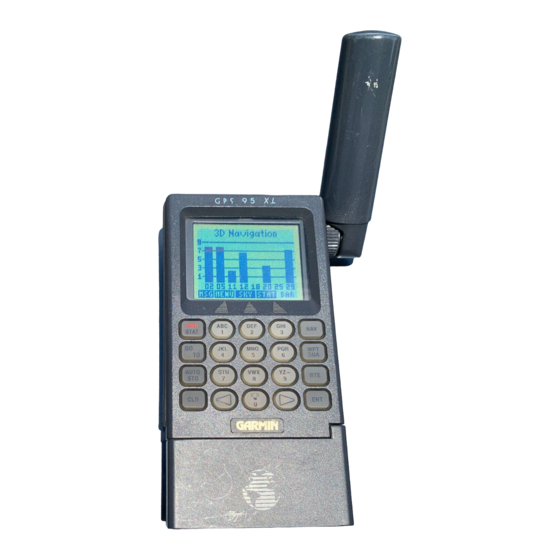
When four or more satellites with good geometry are available, the GPS 95 will automatically operate in the 3D mode in which latitude, longitude and altitude are computed. If only three satellites are available, the unit will operate in 2D mode in which only latitude and longitude are computed. When operating in the 2D mode, the unit will use the last computed altitude or your last entered altitude. -
Page 22: Learning To Use The Gps
2.9 LEARNING TO USE THE GPS 95 If you are using the GPS 95 for the first time, you are encouraged to read Chapter 3 which introduces the GPS 95's waypoint, airspace and database features, Chapter 4 on the use of the GOTO key, and Chapter 5 for navigating to a waypoint. -
Page 23: Waypoints And Airspaces
WAYPOINTS AND AIRSPACES The GPS 95 features a Jeppesen database providing Americas or International navigation information. (Refer to Section 1.2 for a specific description of information provided in the database.) The database contains information about waypoints and airspaces. A basic waypoint consists of an identifier (up to six letters and/or numbers) and its location. -
Page 24: Waypoint Categories
3.1 WAYPOINT CATEGORIES Airport Ident The GPS 95 organizes waypoints into one of five different categories: airports, VORs, NDBs, intersections and user waypoints. This organization is much like that of a file cabinet in which each drawer represents a different type of information. -
Page 25: Airport Information
3.2 AIRPORT INFORMATION The GPS 95 features extensive information on airports: · Identifier, facility name, city and state · Position and elevation · Fuel Services · Communication frequencies · Runway information with graphic configuration The airport information pages may be displayed from the Waypoint Definition Page. - Page 26 · Press the right arrow key to move the cursor to the right of “APT”. · Enter the identifier of the desired airport using the alphanumeric and arrow keys. Press ENT. (Note: The airport identifiers in the GPS 95 database follow the standards set by the International Civil Aviation Organization [ICAO].) ·...
- Page 27 Airport Communication Information The airport communication information includes identifier (selectable), ATIS, ground, tower and unicom (or multicom) frequencies for the selected airport. Up to five communication frequencies may be displayed at a time. Additional frequencies may be viewed by scrolling. To scroll through available frequencies...
-
Page 28: Vor Information
Runway surface · hard · turf · sealed · gravel · dirt · soft · unkwn · water 5) Lighting · no lights · pc lights · pt lights · ft lights · unknown 6) Graphic runway configuration, if available The graphic runway configuration will display the layout of available runways. -
Page 29: Ndb Information
The GPS 95 also features considerable information on VORs: 1) Identifier (selectable) 2) Facility name 3) City/state 4) Frequency 5) DME indication, if applicable, for co-located DME or TACAN 6) Location (latitude/longitude or grid system) You may select the desired VOR by its two-to-three-character identifier, facility name or city/state. -
Page 30: Intersection Information
The GPS 95 displays the following information on NDBs: 1) Identifier (selectable) 2) Facility name 3) City/state 4) Frequency 5) Location (latitude/longitude or grid system) You may select an NDB by its one-to-three-character identifier, facility name or city/state. (See Section 3.10 for information on selecting NDBs by facility name or city/state.) To select an NDB by identifier... -
Page 31: User Waypoint Information
Intersections are only selected by identifier. Once an intersection is selected, the identifier of, bearing from, and distance from the nearest VOR will be displayed. (NOTE: The VOR is simply the nearest facility and is not necessarily the VOR used to define the intersection.) To select an Intersection... -
Page 32: Creating User Waypoints
User waypoints are only selected by the identifier that you assign. To select a user waypoint... · Press WPT/SUA and, if needed, the WPT softkey to display the Waypoint Definition Page. · If “USR”, for user waypoint, is not currently displayed in the upper left corner: press the right arrow key to place the cursor on the cyclic field, then press CLR (repeatedly) until “USR”... - Page 33 · Enter the identifier of the new waypoint using the alphanumeric and arrow keys. Press ENT when complete. The cursor will move to the position coordinates. · Enter the position of the new waypoint. Press ENT after data is entered into each field.
-
Page 34: Waypoint List
Once the waypoint location is created, the user comment field will automatically be filled with the date and time the waypoint was created. You may enter a different user comment by placing the cursor over this field and entering the new comment with the alphanumeric and arrow keys, followed by ENT when complete. -
Page 35: Using Waypoints
NOTE: If you attempt to delete a GOTO or route waypoint, a message will be displayed. You must cancel the GOTO or delete the route before you can delete the waypoint. (See Chapter 4 and Section 6.5.) The Waypoint List Page also gives you the option of deleting all user waypoints at one time. -
Page 36: Using Waypoints By Scanning
The waypoint identifier and number of duplicates are displayed on the first line of the Duplicate Waypoint Page. On the following lines, the waypoint type and region for each duplicate waypoint is displayed, sorted by distance from present position. From this list you may select the desired waypoint by placing the cursor on the desired waypoint, using the arrow keys, and pressing ENT. - Page 37 · Press WPT/SUA to begin scanning. · Press the right arrow key to sequence through the available waypoints. If you pass the desired waypoint, you may press the left arrow key to scan backwards through the list. · Once the desired waypoint is selected, press ENT to accept the waypoint and complete the scan.
-
Page 38: Reviewing Waypoints
· Select the desired waypoint category (airport, VOR or NDB only) by pressing CLR (repeatedly). · Press the right arrow key twice to place the cursor on the facility name. · Enter the starting letter, or letters, of the facility name. You may limit the scan to the desired level by designating the number of starting letters (as described previously when scanning by identifier). -
Page 39: Nearest Waypoints
· If the waypoint is an airport, a second cyclic field will appear in the upper right corner of the page. You may select between location (Locn), communication (Comm) or runway (Rnwy) information by highlighting this cyclic field and pressing CLR until the desired information is displayed. -
Page 40: Sua Page And Messages
The nearest waypoint feature can be used in conjunction with the GOTO key to provide instantaneous navigation information to a nearby waypoint. Simply place the cursor over the desired nearest waypoint identifier and press GOTO, followed by ENT. The GPS 95 will immediately plot a course from your present position to the nearby waypoint. - Page 41 You may view additional information for each SUA / controlled airspace for which a message is provided by utilizing the SUA Page. The SUA page lists any SUA you are within, near or that lies ahead (less than ten minutes away). For SUAs that lie ahead of you, the estimated time en route (ETE) before entry may also be displayed.
-
Page 42: Getting There Fast - Goto
GETTING THERE FAST - GOTO The GOTO function allows you to quickly set a course from your position to any waypoint. To activate the GOTO function... · Press GOTO. The GOTO Page will be displayed with the cursor on the GOTO waypoint field. If the GPS 95 is currently navigating to a waypoint, that waypoint will be offered as the default GOTO waypoint. - Page 43 You may cancel the GOTO function at any time. To cancel the GOTO function... · Press GOTO. The GOTO Page will be displayed. · Press CLR. The GOTO waypoint name will become blank. · Press ENT. The GPS 95 will start to navigate using the active route, if it has been programmed.
-
Page 44: Navigation Information
NAVIGATION INFORMATION The GPS 95 features four navigation pages. You may select the desired page by pressing NAV and, if needed, the appropriate softkey. Navigation Summary Page Map Display 5.1 NAVIGATION SUMMARY PAGE GOTO or Active Leg Field #1 Field #3 CHAPTER 5 Present Position Page Map Configuration Page... - Page 45 The Navigation Summary Page displays direction, distance and speed information to guide you along a route or to a GOTO destination. Included is a graphic course deviation indicator (CDI), at the bottom of the page, which illustrates your position relative to the course. The current CDI scale setting is shown at each end of the CDI scale.
-
Page 46: Map Display
Notice that the Navigation Summary Page has four cyclic fields. With these cyclic fields you may configure your GPS 95 to display navigation information according to your preferences. (See Appendix B for a description of navigation terms.) The field options are as follows: Field #1 (top left) ·... - Page 47 The GPS 95 also features a Map Display which shows a graphic top view of your location. The current ground speed is indicated at the top right corner of the display. The top left corner defines the orientation of the Map Display: “North up”, “Track up”, or “Desired track up.”...
-
Page 48: Map Configuration
To set the Map Display scale... · With the cursor on the scale setting number, press CLR to sequence through the available scale settings. (HINT: The scale setting may also be selected by pressing the alphanumeric key that corresponds to the desired scale.) 5.3 MAP CONFIGURATION The Map Configuration Page allows you to tailor the GPS 95’s Map Display to your preferences. -
Page 49: Present Position
An auto zoom feature is provided for automatic scaling of the Map Display. With this feature on, the scale setting will automatically adjust as you approach your destination. Starting at 80 nautical miles during en route flight, the Map Display will zoom in progressively, stopping at a one nautical mile scale as you arrive at your destination. -
Page 50: Sample Trip
When the GPS 95 is performing 2D navigation, the last known altitude will be used to calculate a present position. If the altitude is not accurate within a few hundred feet you should manually enter your altitude. To enter the altitude (2D only)... ·... - Page 51 Since this is a simulated trip, you will select the simulator mode and indicate a starting location for the trip. Your simulated trip will begin at an intersection called LENEX in Lenexa, Kansas. (NOTE: This sample trip assumes that the Americas database is used. If you are using the International database follow the general steps outlined in this sample trip, but substitute waypoints from your area of interest.) To select simulator mode and define a starting location...
- Page 52 The Operating Mode Page is displayed showing the current operational mode. Place the cursor on the operational mode field using the right arrow key. Press CLR until “Simulator?” is selected. *Repeat until desired mode is selected Press ENT to accept simulator mode. The cursor is now on the reference waypoint identifier.
- Page 53 *Plus POSN softkey if needed From your starting location at the “LENEX” intersection you may plot a course and navigate to a nearby airport. For this sample trip you will fly to KCOU, Columbia Regional Airport. To select a destination waypoint... 5-10 The cursor is over the reference bearing.
- Page 54 *Press the alphanumeric and arrow keys as needed to select desired identifier The GPS 95's simulator mode allows you to enter a ground speed which is used to animate the navigation displays. To enter a simulated speed... *Press the alphanumeric keys as needed to enter ground speed Press the “4”...
- Page 55 Additional information is available from the Navigation Summary Page. You may recall from Section 5.1 that this information is viewed by highlighting one of the four cyclic fields and pressing CLR. Let's take a look at one of those fields now. To view additional navigation information...
- Page 56 The GPS 95's Map Display is also useful to help “orient” yourself. The Map Display can show area airports, NAVAIDS, and intersections as points of reference. To view the Map Display... *Continue pressing CLR until desired scale is selected The simulated trip has demonstrated only a small portion of the GPS 95's many features.
-
Page 57: Routes
CHAPTER 6 ROUTES KSTL (Active from waypoint) (Active to waypoint) Active Leg KTUL The GPS 95 offers a route navigation feature for you to navigate along a pre- defined sequence of waypoints. The GPS 95 route capability allows you to create and store twenty routes, numbered 0 through 19, containing up to 30 waypoints each. -
Page 58: Route Definition
There are 3 route pages. You may select the desired page by pressing RTE and, if needed, the appropriate softkey. Route Definition Page 6.1 ROUTE DEFINITION The Route Definition page allows you to create, change, review, copy, and activate routes. Remember that route 0 is always the active route. If you create a route in route 0, you should copy it into an empty storage route (1- 19). -
Page 59: Creating And Copying Routes
On the route number field, you may choose between routes 0 through 19 with CLR. Next to this is a route action field which allows you to activate the route, clear the route, copy the route to another location, or invert the order of the waypoints in a route and activate it. -
Page 60: Activating And Inverting Routes
6.3 ACTIVATING AND INVERTING ROUTES Routes are also activated on the Route Definition Page. You may activate any route in the displayed order, or in reverse order. (NOTE: Remember, when a new route is activated, the previous contents of route 0 will be overwritten. -
Page 61: Deleting Routes
· If you attempt to add a waypoint to a route that already contains 30 waypoints, you will be informed with the message, “Route is Full”. NOTE: You may also edit a route from the Active Route Page. (See Section 6.6.) 6.5 DELETING ROUTES You may delete an unwanted route from the Route Definition Page. -
Page 62: Route List
The waypoint list displays route waypoints starting with the “active to” waypoint. For each waypoint, additional information is available. The first column displays Distance (DIS). The second column is a cyclic field that displays Estimated Time Enroute (ETE, in hours/minutes or minutes/seconds, as appropriate), Estimated Time of Arrival (ETA), or Desired Track (DTK). -
Page 63: Autostore
CHAPTER 7 AUTOSTORE The AutoStore function allows you to capture your position at the touch of a button for future reference. This function saves your current position as a waypoint. Additionally, you may record your navigation path by inserting the captured waypoints directly into a route. -
Page 64: Building Routes With Autostore
You may capture and save your position as a waypoint, without adding it to a route, by leaving the route storage number field blank. To capture present position ... · Press AUTOSTO. The pre-assigned waypoint identifier and captured position are displayed. (NOTE: The AutoStore location is captured as soon as you press AUTOSTO. - Page 65 · From the starting location, press AUTOSTO to capture the position. (NOTE: The unit must be in 2D or 3D navigation mode when capturing your starting position. If the unit is still acquiring satellites, and you press AUTOSTO, the last known position will be captured and saved.) ·...
-
Page 66: Gps Status And Menu Pages
CHAPTER 8 GPS STATUS AND MENU PAGES The GPS 95 contains a vast array of functions, many of which you may custom tailor to your preferences. Additionally, the unit can provide current status information regarding the satellites being received and display messages relevant to your current operations. -
Page 67: Bar Graph Page
8.1 BAR GRAPH PAGE signal strength for that satellite. If a satellite is visible, but not being received, the signal strength will be blank. The receiver status is also shown at the top of the page. In this example, the unit is acquiring satellites. -
Page 68: Satellite Status Page
“Not Usable” page. There are two additional receiver status messages available when using an RTCM input: “2D Nav - Diff” “3D Nav - Diff” 8.2 SATELLITE STATUS PAGE be used as absolute measures of accuracy. (See Appendix B for definitions of these terms.) The GPS 95 is unusable (possibly due to incorrect initialization data or abnormal satellite... -
Page 69: Satellite Skyview Page
8.3 SATELLITE SKYVIEW PAGE mountains, or other obstructions. Satellite elevation is indicated by the distance (of a given satellite) from the center of the display. The center represents directly overhead, or 90° elevation. The inner ring represents 45° elevation and the outer ring is the horizon, or 0° elevation. If a satellite is not currently being received, it will be highlighted on the display. -
Page 70: Operating Mode/Nearest Airport Search
Once an item is selected PREV, MENU, and NEXT page options will be displayed. The softkeys allow changing to the previous (PREV) and next (NEXT) pages for that category. The MENU softkey takes you back to the sub-menu page. (HINT: The PREV and NEXT softkeys will only select the pages within that category. -
Page 71: Units/Heading Setup
The Operating Mode/Nearest Airport Search Page also allows you to select the characteristics of the GPS 95's nearest airport function. Pilots of large, high-performance aircraft may direct the nearest airport function to ignore those airports at which it would be difficult, if not impossible, to land their aircraft. -
Page 72: Map Datum Selection
Select the desired distance, speed and altitude units by highlighting the “NAV” field and pressing CLR. You may choose between nautical (nautical miles/knots/feet), statute ( miles/miles per hour/feet), or metric (kilometers/ kilometers per hour/meters) units. (NOTE: The NAV units setting also defines the pressure, temperature and vertical speed units that will be used for E6-B calculations.) Heading information can be displayed referencing magnetic north... -
Page 73: Audio And Display Setup
To change the pre-defined datum... · Highlight the “Change?” field and press ENT. · With the arrow keys, find the desired datum and highlight it. · Press ENT. The new datum is selected. map datums. If the pre-defined map datums do not correspond to the chart you are using and you are unsure of the correct entries required to correspond to that chart, contact the chart manufacturer. -
Page 74: Track Log Setup
To turn audio tones on/off... · Highlight the tone option field. · Press CLR to select the desired option. You may also adjust the contrast of the GPS 95 display to your preferences. To change the display contrast... · Highlight “Change Contrast?” and press ENT. ·... - Page 75 needed, it may be cleared by highlighting “Clear Track Log?” and pressing ENT. If the “fill” option is selected, a “memory full” message will be displayed when all available memory has been used and you must clear the track log to store additional track information.
-
Page 76: Sua Alarms
8.10 SUA ALARMS (ALARMS) NOTE: The GPS 95 always provides alerts for Prohibited areas. No selection is provided for this feature. To turn an SUA alarm on or off... · Using the arrow keys, highlight the on/off cyclic field beside the desired airspace type. -
Page 77: Arrival Alarm / Cdi Setup
8.11 ARRIVAL ALARM / CDI SETUP (ALARMS) The CDI alarm will notify you with an alarm tone and the message “CDI Alarm” if you have deviated off course beyond the limit that you set. (This can be useful while flying on an airway or navigating a narrow corridor.) To set the CDI alarm... - Page 78 The GPS 95 also features an alarm clock which can provide an alarm tone and the message “Alarm Clock” at a time that you specify. To set the alarm clock... · Highlight the alarm clock time and enter the desired alarm time. NOTE: The alarm time may be either UTC or local time depending on the setting on the Date/Time Page.
-
Page 79: Input/Output Setup
(NONE/NMEA), RTCM input/NMEA output (RTCM/NMEA) or RTCM input (RTCM/NONE). A second cyclic field also appears when the GARMIN input/output is selected. The GARMIN option allows you to exchange data such as waypoints, routes, track logs and satellite almanac data with another GPS 95 or with a PC-compatible computer. - Page 80 To select GARMIN input/output... · Place the cursor on the input/output format field. · Press CLR until the GARMIN input/output option is selected. · Press the right arrow key. · Select “HOST”, “REQUEST”, or “SEND” by pressing CLR. (NOTE: You should select the “HOST” option when using the GPS 95 with a PC.
-
Page 81: Beacon Receiver Setup
Also, the “Distance” field will show the distance to the beacon being received. 8-16 The Beacon Receiver Setup Page allows the GPS 95 to control GARMIN's GBR 21 differential beacon receiver. In order to use the beacon receiver, the “RTCM/NMEA” and “NMEA 0183”... -
Page 82: Messages
The most recently tuned frequency is at the top of the list. If the tuned frequency, station identifier and position were available when the frequency was last tuned, the list will also display the “Stn ID” number and the distance to the transmitting beacon. -
Page 83: Trip And Fuel Planning
To calculate density altitude and true airspeed... · Place the cursor on the indicated altitude (IAlt) field. · Enter the indicated altitude from your altimeter and press ENT. · Enter your calibrated airspeed (CAS) and press ENT. If you do not know your calibrated airspeed, use indicated airspeed instead. - Page 84 The final step is to enter speed and fuel flow rates. The GPS 95 will then calculate the desired track (DTK), fuel requirements (REQ), distance (DIS), and estimated time enroute (ETE). To perform a trip and fuel plan, waypoint to waypoint... ·...
-
Page 85: Date/Time Settings
8.17 DATE/TIME SETTINGS (E6-B) The cyclic field for “Display” options determines which time, UTC or Local, will be displayed on all other GPS 95 pages. To display UTC or local time... · Highlight the time display field. · Press CLR to select the desired time reference. The timer field can be selected as “count up”... -
Page 86: Sunrise/Sunset Planning
To set the count down timer... · Place the cursor on the timer option field. · Press CLR to select “count down”. · Press the right arrow key. · Enter the number of hours to count down from and press ENT. ·... -
Page 87: Vertical Navigation Planning
8.19 VERTICAL NAVIGATION PLANNING (E6-B) Pilots will find the GPS 95's vertical navigation (VNAV) function useful for calculating vertical speed requirements. In order to use the VNAV feature, aircraft ground speed must be greater than 35 knots. To calculate vertical speed requirements... ·... - Page 88 To activate the VNAV function... · Review the calculated vertical speed. If you wish to change the vertical speed: place the cursor on the vertical speed (At) field, enter the desired vertical speed and press ENT. · Place the cursor over the “VN” field. ·...
-
Page 89: Sample Trip Using Routes
SAMPLE TRIP USING ROUTES Now that you have gained a basic understanding for your GPS 95, you are ready to explore the route capabilities of this unit. The sample illustrations in this chapter assume that the factory default settings have not been changed. - Page 90 Setting the simulator mode and initial position... The welcome screen is displayed and the GPS 95 performs several self tests. After about five seconds the Database Page is displayed. Review the page to see if the database is current and press ENT to confirm the page.
- Page 91 The Operational Setup sub-menu is displayed with “Operation Mode” highlighted. Press ENT to select “Operation Mode”. The Operating Mode Page is displayed showing the current operational mode. Press the right arrow to place the cursor on the operational mode field. Press CLR (repeatedly) until “Simulator?”...
- Page 92 *Continue pressing the alphanumeric and arrow keys, if needed, to enter the waypoint identifier Before you begin the trip, all waypoints used along the route should be in memory. If you are using the Americas Database, only the location for the Whitewater Bay area needs to be entered into memory.
- Page 93 Creating the “WWBAY” user waypoint... *Plus WPT softkey, if needed *Press repeatedly until “USR” is displayed Press WPT and the WPT softkey, if needed, to select the Waypoint Definition Page. Press the right arrow key to place the cursor on the waypoint category field. Press CLR (repeatedly) until “USR”...
- Page 94 *Continue pressing the alphanumeric and arrow keys, if needed, to select waypoint identifier *If needed to select proper hemisphere *Continue pressing the alphanumeric keys to enter the latitude minutes Continue pressing the alphanumeric and, if needed, arrow keys until the waypoint identifier has been entered.
- Page 95 *Enter the longitude using the same steps shown above This trip will take you to an intermediate destination (Whitewater Bay) and then a final destination (Key West). You could go to each destination using the GOTO function as described in Chapter 4. (Select GOTO WWBAY, then, upon reaching WWBAY, select GOTO KEYW.) However, for this sample trip, the route capabilities of the GPS 95 will be utilized.
- Page 96 *Continue pressing the alphanumeric and arrow keys, if needed, to enter the waypoint identifier that the route is empty; it does not contain any waypoints. (If route 1 is not empty, select a different route.) Press the right arrow key twice to place the cursor on the first waypoint identifier field.
- Page 97 *Enter the next waypoint identifier using the alphanumeric keys *Enter the last waypoint identifier using the alphanumeric and arrow keys As you can see, you have just created a route that will take you from Fort Myers, over Whitewater Bay and on to Key West. Once activated, the GPS 95 will calculate navigation data based on the route.
- Page 98 Before you take off, you may want to view communications frequencies and runway layout for Fort Myers - Southwest Florida International. To view airport information... *Plus WPT softkey, if needed 9-10 Press ENT to activate the route. The Active Route Page is displayed. This page displays the “active from”...
- Page 99 *Continue pressing the alphanumeric and arrow keys, if needed, to enter waypoint Continue pressing the alphanumeric identifier and, if needed, arrow keys until the waypoint identifier has been entered. Press ENT when complete. Location information will be displayed for the airport (as well as available fuels).
- Page 100 In order to animate the GPS 95's displays you will need to enter a simulated speed. To set the simulated speed... *Plus NAV softkey, if needed *Continue pressing the alphanumeric keys to enter the ground speed 9-12 Press NAV and the NAV softkey, if needed, to select the Navigation Summary Page.
- Page 101 As your flight progresses, you can monitor the nearest airports at any time. This feature can be particularly valuable in the event of an in-flight emergency. To view the nearest airports... *Plus NRST softkey, if needed In an actual emergency you could instantly plot a course to a nearest airport by highlighting the desired airport (using the arrow keys), pressing GOTO and ENT.
- Page 102 · If you wish to stop the simulation, simply turn the GPS 95 off. We recommend that you delete the route and waypoint created in this simulation prior to using your unit again. (See Section 3.8 for information on deleting waypoints and Section 6.5 for information on deleting routes.) 9-14...
-
Page 103: Sua Features Explained
SUA FEATURES EXPLAINED! By now, the operation of the GPS 95's SUA features should seem easy: · Messages are provided to alert you of nearby special-use and controlled airspaces. · The SUA Page provides additional information about each of the airspaces. - Page 104 Your destination airport is Batesville Regional (KBVX), inside the MOA. As you descend toward the airport the “Inside” indication on the SUA Page disappears once you are below the floor of Shirley 1, plus any altitude buffer setting (and position error) you may have entered. For example, if you enter 500 feet for an altitude buffer setting, the “Inside”...
-
Page 105: Flying Near An Sua's Boundary
10.2 FLYING NEAR AN SUA' BOUNDARY < 2 nm & In our second example, you are again flying due west at 10,500 feet, but this time your planned course is parallel to the northern boundary of Shirley 1 MOA and less than two nautical miles away. When you reach Location #1 the “SUA Near <... -
Page 106: Sectorized Airspace - Near Versus Ahead
As you continue on this new course an “Inside SUA” message occurs at Location #4. No further messages are provided, but at Location #5 the SUA Page will indicate “Near” for Shirley 1. At Location #6, over two nautical miles away from the MOA, Shirley 1 will no longer appear on the SUA Page. -
Page 107: Multiple Suas
At Location #1 you reach your en route altitude of 3,000 feet and the GPS 95 alerts you of the controlled airspace ahead with, “SUA Ahead < 10 min”. The outer ring of the Class B airspace only extends down to 4,000 feet MSL. The airspace you are being warned of is the second ring (sector) that extends from 8,000 to 3,000 feet MSL. - Page 108 In our final example, you are flying westbound toward Sundance MOA. Adjacent to this MOA are two restricted areas: R-2501S and R-2501E. Sundance MOA extends from 500 feet AGL to 10,000 feet MSL. Since the MOA floor is an AGL altitude, the GPS 95 will provide SUA messages for this airspace at all altitudes below 10,000 feet MSL.
- Page 109 All the examples described in this section are based on real airspaces. If your unit contains the Americas database, you may use the Simulator Mode to duplicate these scenarios and observe how the unit would actually operate when flying near an SUA. (Refer to Section 5.5 for more information on using Simulator Mode.) The table below shows the starting position, altitude, ground track and speed used in each example.
-
Page 110: Amessages
Dbase Mem Failed - The GPS 95 has detected a failure in its flash memory when using the PC Database Update Kit. If this message occurs, the database is unusable and the unit should be taken to an authorized GARMIN service center. - Page 111 Expect a rapid change in the CDI. Memory Battery Low - The battery that sustains user memory is low and should be replaced by an authorized GARMIN service center as soon as possible. Failure to do so may result in loss of stored data, including all waypoints and routes.
- Page 112 Route is Full - An attempt has been made to add more than 30 waypoints to a route. The GPS 95 will not allow more than 30 waypoints per route. Route Not Empty - An attempt has been made to copy a route to another non-empty route.
- Page 113 VNAV cancelled - The VNAV function has been cancelled due to a change in the active route. WPT Exists ____ - You have entered a waypoint name on the AutoStore Page that already exists in memory. Enter a waypoint name that does not exist.
-
Page 114: Glossary And Navigation Terms
APPENDIX B GLOSSARY AND NAVIGATION TERMS B.1 DEFINITIONS This section provides an illustration of and definitions for the navigation terms used in this manual. - Page 115 Velocity/time terms: Ground speed. GS is the speed measured relative to a ground position; also known as velocity over ground (VOG). Estimated time of arrival. ETA is the estimated time you will reach the “active to” waypoint based on current GS. This time is selectable as either UTC or local.
-
Page 116: Course To Steer (Cts
B.2 COURSE TO STEER (CTS) Course To Steer is a GARMIN exclusive that recommends an optimal direction to steer that will guide you to the course and allow you to proceed efficiently along your route. - Page 117 95 chooses the closest leg with a desired track of 45 degrees but your position happens to be two nautical miles off course. The unit will automatically compute the optimal course to steer (which is due north in this example). Press the NAV key until the Nav Summary Page is displayed, then select “CTS”...
-
Page 118: Installation And Maintenance
INSTALLATION AND MAINTENANCE C.1 SPECIFICATIONS GPS 95 SPECIFICATIONS —————————————————————————————- PHYSICAL Case: Size: Weight: POWER Input Consumption ENVIRONMENTAL Temperature: Humidity: PERFORMANCE Receiver: Frequency: Acquisition Time: (typical) APPENDIX C Waterproof w/ Battery Pack - 3.23"w x 6.26"h x 1.46"d (82mm x 159mm x 37mm) w/o Battery Pack - 3.23"w x 4.87"h x 1.46"d (82mm x 124mm x 37mm) 14 ounces (0.4 kg) without battery pack 19... - Page 119 Update Rate: Accuracy: Dynamics: INTERFACES NMEA 0180 NMEA 0182 NMEA 0183 Version 1.5 Approved sentences: GPBWC, GPGLL, GPRMB, GPRMC, GPXTE, GPVTG, GPWPL Proprietary sentences: PGRMM (map datum), PGRMZ (altitude), PSLIB (beacon receiver control) NMEA 0183 Version 2.0 Approved sentences: GPGGA, GPGLL, GPGSA, GPGSV, GPRMB, GPRMC, GPRTE, GPWPL Proprietary sentences: PGRME (estimated error), PGRMM (map datum), PGRMZ...
-
Page 120: Electrical Wiring
ELECTRICAL WIRING The GPS 95 power/data cable allows you to connect the unit to vehicle power systems, other electronics, and a remote alarm/beeper. The power/data cable has a 7-pin intermediate connector to facilitate quick disconnection of all electrical connections and easy removal of the entire yoke mount from the aircraft. -
Page 121: Yoke Mount Installation
To connect to a remote alarm system... · Connect the BLUE harness lead to the negative side of a transistor alarm or relay switch. · Connect the positive side of the alarm or relay to the positive side of the 5 to 40 volt DC power source. The GPS 95 may be connected to a PC-compatible computer using a NMEA 0183 data interface or to marine electronics such as an autopilot or plotter which use an NMEA 0180, NMEA 0182 or NMEA 0183 data interface. - Page 122 The yoke mount clamp will need to be reconfigured in order to fit the following: Bonanza, Baron and some other Beech models with center column control. To reconfigure the yoke mount... · Completely unscrew the upper knob. · Re-attach the plastic yoke mount bracket to the metal C-clamp assembly using the alternate position as shown.
- Page 123 To attach the yoke mount to the control yoke... · Open the clamp jaw to its widest extent by unscrewing the lower knob. · Slip the clamp over the horizontal member of the control yoke. Position the clamp as far as possible toward the center column. ·...
- Page 124 To substitute the lower knob with shortened stud... · Peel back the protective rubber on the V-block. · Use a 1.5mm hex wrench to remove the M1.7 hex head screw. · Completely unscrew the lower knob. · Screw in the alternate lower knob. ·...
-
Page 125: Yoke Mount Operation
C.4 YOKE MOUNT OPERATION Once installed on the yoke, the yoke mount may be adjusted to provide the optimum viewing angle for your GPS 95. To adjust the yoke mount viewing angle... · Loosen the upper knob. · Rotate the bracket up or down on the ratchet. ·... - Page 126 The yoke mount has been designed for easy insertion and removal of your GPS 95 if you wish to use the unit in another airplane or vehicle, to plan at home, or to prevent theft. To insert the GPS 95 into the yoke mount... ·...
-
Page 127: Surface Mounting
· Disconnect the antenna or antenna cable. · Apply enough force to the release tab to allow the unit to pass as shown above. · Pull the bottom of the GPS 95 out. Then rotate the top downward and out. NOTE: The portable antenna is removed by gripping the antenna at its base (on the knurled knob) and rotating 1/4 turn counterclockwise. - Page 128 · Remove the power/data cable screws. · Remove the coinslot screw · Slide the cradle off of the yoke mount bracket as shown. To attach the cradle and power/data cable to the surface mount... · Slide the connector into the corresponding slot in the cradle as shown. ·...
-
Page 129: Portable Antenna Installation
C.6 PORTABLE ANTENNA INSTALLATION The GPS 95 is supplied with a portable antenna mount that allows the antenna to be affixed to a windshield or any smooth surface using a suction cup mount and a six foot extension cable. As an alternative, the suction cup can be removed and replaced with the plastic shoulder washer and self- threading screw to permanently attach the mounting bracket to the glare shield. -
Page 130: Maintenance
C.8 MAINTENANCE The GPS 95 is constructed of high quality material and should not require user maintenance. Please refer any repairs to an authorized GARMIN service center. (The unit contains no user serviceable parts. Do not attempt repairs yourself.) Never allow gasoline or solvents to come into contact with your unit. -
Page 131: Product Support
“Memory Battery Low”. You should return your unit to an authorized GARMIN service center as soon as possible for service. Failure to do so may result in loss of data each time you turn your unit off (indicated by the message “Stored Data Lost”). -
Page 132: D Map Datums
The following is a list of the GPS 95 map datum selections and the corresponding map datum name (including the area of application): Adindan Afgooye AIN EL ABD 1970 Anna 1 Astro 1965 ARC 1950 ARC 1960 Ascension Island ‘58 Astro B4 Sorol Atoll Astro Beacon “E”... - Page 133 Geodetic Datum ‘49 Guam 1963 Gux 1 Astro Hjorsey 1955 Hong Kong 1963 Indian Bangladesh Indian Thailand Ireland 1965 ISTS 073 ASTRO ‘69 Johnston Island Kandawala Kergulen Island Kertau 1948 L.C. 5 Astro Liberia 1964 Luzon Mindanao Luzon Philippines Mahe 1971 Marco Astro Massawa Merchich...
- Page 134 Nahrwn Saudi Arbia Nahrwn United Arab Naparima BWI Observatorio 1966 Old Egyptian Old Hawaiian Oman Ord Srvy Grt Britn Pico De Las Nieves Pitcairn Astro 1967 Prov So Amricn ‘56 Prov So Chilean ‘63 Puerto Rico Qatar National Qornoq Reunion Rome 1940 RT 90 Santo (Dos)
- Page 135 UTC TIME TO LOCAL TIME OFFSET Reference the chart below to find the UTC-to-local time offset for your longitude zone. (If you are in a daylight savings time zone, add one hour to the offset.) For example, if you are at longitude W081°00.00' and UTC time is 16:00, local time is 11:00 standard time.
- Page 136 "Active from" waypoint Active leg Active Route Page "Active to" waypoint Airport communication information Airport information Airport location information Airport runway information Alarm clock Alphanumeric field Alphanumeric keys Altitude, entering Antenna, installing Antenna, removing Arrival alarm Arrival/CDI Page Arrow keys Audio/Display Page Audio tones AutoLocate...
- Page 137 (EPE) Estimated time enroute (ETE) Estimated time of arrival (ETA) Facility names, scanning Fields Front panel Fuel services GARMIN input/output GOTO, activating GOTO, cancelling GOTO function GOTO Key GPS status Graphic runway configuration Ground speed (GS) Heading reference, selecting Initial position, defining...
- Page 138 Page annunciator Page options PC Database Update Kit PCX5AVD Software Kit Present Position Page Product support PWR/STAT Key Receiver status messages Rechargeable NiCad battery Relative bearing pointer Reviewing waypoints Route Definition Page Route List Page Routes activating copying creating deleting editing inverting RTCM input...
- Page 139 VNAV, activating VNAV altitude (V) Vertical navigation (VNAV) Vertical speed, calculating Viewing messages VOR information Waypoint categories Waypoint Definition Page Waypoint List Page Waypoints nearest reviewing scanning using Winds aloft Wiring, electrical WPT/SUA Key Yoke mount, installation Yoke mount, operation Zero Key 8-23 8-22...
- Page 140 GARMIN / Europe Ltd. GARMIN International, Inc. Robert House, Station Approach 9875 Widmer Road Romsey, Hampshire SO51 8DU UK Lenexa, KS 66215 USA 190-00080-00 Rev. A...