Panasonic R410A Installation Instructions Manual
Split system air conditioner
Hide thumbs
Also See for R410A:
- Installation instructions manual (240 pages) ,
- Service manual (231 pages) ,
- Installation instructions manual (28 pages)
Table of Contents
Advertisement
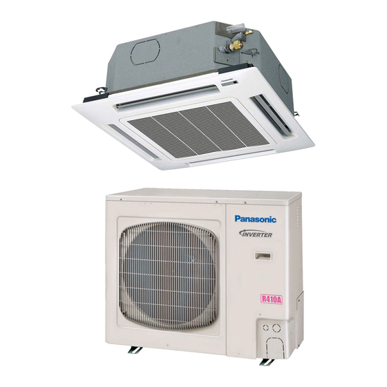
INSTALLATION INSTRUCTIONS
Split System Air Conditioner
This air conditioner uses the refrigerant R410A.
External diameter of service port R410A: 5/16"
NOTE
Model No.
Outdoor Units
Type
Outdoor Unit Type
U
Single
Indoor Units
Type
Indoor Unit Type
U1
4-Way Cassette
K1
Wall Mounted
T1
Ceiling
F1
Low Silhouette Duct
Remote Controllers
Timer Wired Remote Controller
Wireless Remote Controller
85464369531020
26
36
U-26PE1U6
U-36PE1U6
U-26PS1U6
U-36PS1U6
26
36
S-26PU1U6
S-36PU1U6
S-26PK1U6
S-26PT1U6
S-36PT1U6
S-26PF1U6
S-36PF1U6
CZ-RTC2
CZ-RWSU1U
CZ-RWSC1U
CZ-RWSK1U
1
42
U-42PE1U6
Cooling/Heating
U-42PS1U6
Cooling
42
S-42PU1U6
with Wired Remote Controller: CZ-RTC2
with Wireless Remote Controller: CZ-RWSK1U
S-42PT1U6
with Wired Remote Controller: CZ-RTC2
with Wired Remote Controller: CZ-RTC2
Timer Wired Remote Controller comes with Instructions Manual.
for U1 and T1 type Indoor units
for F1 type Indoor units
for K1 type Indoor units
Units should be installed by licensed contractor according to
local code requirements.
Remarks
Remarks
CV6233186979
Advertisement
Table of Contents

Related Manuals for Panasonic R410A


Summary of Contents for Panasonic R410A
-
Page 1: Installation Instructions
INSTALLATION INSTRUCTIONS Split System Air Conditioner This air conditioner uses the refrigerant R410A. External diameter of service port R410A: 5/16" NOTE Model No. Outdoor Units Type Outdoor Unit Type Remarks U-26PE1U6 U-36PE1U6 U-42PE1U6 Cooling/Heating Single U-26PS1U6 U-36PS1U6 U-42PS1U6 Cooling Indoor Units... -
Page 2: Important
Highly dangerous electrical voltages are used in this mix air except for specifled refrigerant system. Carefully refer to the wiring diagram and these (R410A) in refrigeration cycle. It instructions when wiring. Improper connections and inad- WARNING causes capacity down, and risk of equate grounding can cause accidental injury or death. -
Page 3: Check Of Density Limit
Refrigerant Concentration Level (RCL) of 25 pounds limit. per 1,000 cubic feet for R410A refrigerant. The refrigerant (R410A), which is used in the air condition- For additional guidance and precautions related to er, is safe, without the toxicity or combustibility of ammonia,... -
Page 4: Precautions For Installation Using New Refrigerant
2. Be sure to recharge the refrigerant only in liquid form. 2-1. Since R410A is a non-azeotrope, recharging the refrigerant in gas form can lower performance and cause defects of the unit. -
Page 5: Configuration And Characteristics Of Cylinders
3-2. Use R410A exclusive cylinder only. Confi guration and characteristics of cylinders When charging with a refrigerant cylinder, use an Valve electronic scale for charging refrigerant. In this case, if the volume of refrigerant in the cylinder becomes less than 20% of the fully-charged amount, the composition of the refrigerant starts to change. -
Page 6: Table Of Contents
CONTENTS Page Page IMPORTANT!........2 6. -
Page 7: General
1. GENERAL 1-2. Type of Copper Tube and Insulation Material Copper tubing for connecting the outdoor unit to the This booklet briefl y outlines where and how to install the indoor unit is available in kits which contain the liquid air conditioning system. -
Page 8: Tubing Size
1-4. Tubing Size Single Single type Refrigerant tubing between the indoor and outdoor units should be kept as short as possible. The length of the refrigerant tubes between the indoor and outdoor units are limited by the elevation difference between the 2 units. During tubing work, try to make both Main tubing L the tubing length (L) and the difference in elevation (H1) as short as possible. - Page 9 Table 1-2 Tubing Data for Models U-26PE1U6 U-36PE1U6 U-42PE1U6 Models Tubing Data U-26PS1U6 U-36PS1U6 U-42PS1U6 Liquid tube in. (mm) 3/8 (9.52) 3/8 (9.52) 3/8 (9.52) Tubing size outer diameter Gas tube in. (mm) 5/8 (15.88) 5/8 (15.88) 5/8 (15.88) Limit of tubing length (ft.) Outdoor unit is placed Limit of elevation...
- Page 10 The refrigerant (R410A), which is used in the air conditioner, is safe, without the toxicity or combustibility of ammonia, and is not restricted by laws imposed to protect the ozone layer.
-
Page 11: Selecting The Installation Site
2. SELECTING THE INSTALLATION SITE 2-1. Outdoor Unit Exhaust fan AVOID: heat sources, exhaust fans, etc. (Fig. 2-1) Hot air damp, humid or uneven locations Heat source Out- door choose a place as cool as possible. unit choose a place that is well ventilated and outside air temperature does not exceed maximum 115°F constantly. -
Page 12: Air-Discharge Chamber For Top Discharge
2-2. Air-Discharge Chamber for Top Discharge Be sure to install an air discharge chamber in the Air discharge fi eld when: it is diffi cult to keep a space of min. 20" between the air discharge outlet and an obstacle. Air discharge the air discharge outlet is facing a sidewalk and discharged hot air may bother passers-by. -
Page 13: Dimensions Of Wind Ducting
2-5. Dimensions of Wind Ducting Reference diagram for air-discharge chamber (fi eld supply) For U-26PE(S)1U6 / U-36PE(S)1U6 unit Air discharge chamber Air discharge chamber (base) 21-13/16 (25/32) (25/32) Rectangular hole (both sides) 5-5/32 9-27/32 9-27/32 1-1/16 21-13/16 15/16 17/32 Unit: inch Note: In snowy regions, if there is concern that snow may enter the air discharge chamber, remove the base of the chamber (10 screws) before using. - Page 14 Dimensions of Outdoor Unit with air-discharge chamber (fi eld supply) U-26PE(S)1U6 / U-36PE(S)1U6 unit 6-11/16 4-5/16 25-31/32 Wind direction 2-17/32 21-13/16 9-7/8 Wind direction Wind direction Unit: inch U-42PE(S)1U6 unit 4-5/16 6-11/16 25-31/32 Wind direction 2-11/36 21-13/32 11-13/16 Wind direction Wind Wind direction...
- Page 15 Reference diagram for air-discharge chamber (fi eld supply) U-26PE(S)1U6 / U-36PE(S)1U6 / U-42PE(S)1U6 Required space around outdoor unit If the air discharge chamber is used, the space shown below must be secured around the outdoor unit. If the unit is used without the required space, a protective device may activate, preventing the unit from operating. (1) Single-unit installation Unit: inch The top and both sides must remain open.
-
Page 16: Dimensions Of Snow Ducting
2-6. Dimensions of Snow Ducting Reference diagram for snow-proof vents (fi eld supply) For U-26PE(S)1U6 / U-36PE(S)1U6 unit 30-3/32 Unit top, snow-proof vent Unit left side Unit right side Unit reverse side Unit reverse side Unit sides, reinforcement brackets for snow-proof vent Fastened by screws at 13 locations 3-3/4 11-29/32... - Page 17 Dimensions of outdoor unit with snow-proof vents (fi eld supply) U-26PE(S)1U6 / U-36PE(S)1U6 unit 30-5/64 7-3/64 Wind direction Wind direction Wind direction Wind direction 11-57/64 37-1/64 Wind direction Wind direction Unit: inch U-42PE(S)1U6 unit 30-5/64 7-3/64 Wind direction Wind direction Wind direction Wind direction 37-1/64...
- Page 18 Reference diagram for snow-proof vents – 1 Space requirements for setting – (1) U-26PE(S)1U6 / U-36PE(S)1U6 / U-42PE(S)1U6 [Obstacle to the rear of unit] [Obstacle to the front of unit] Top is open: Top is open: (1) Single-unit installation (2) Obstacles on both sides (1) Single-unit installation Min.
- Page 19 Reference diagram for snow-proof vents – 2 Space requirements for setting – (2) U-26PE(S)1U6 / U-36PE(S)1U6 / U-42PE(S)1U6 [Obstacles to the front and rear of unit] The top and both sides must remain open. Either the obstacle to the front or the obstacle to the rear must be no taller than the height of the outdoor unit.
-
Page 20: How To Install The Outdoor Unit
3. HOW TO INSTALL THE OUTDOOR UNIT 3-1. Installing the Outdoor Unit Drain port (2 locations) Use concrete or a similar material to create the base, and ensure good drainage. 6-11/16 4-21/64 25-63/64 Ordinarily, ensure a base height of 2". or more. If a 8-5/8 5-29/32 drain pipe is used, or for use in cold-weather regions,... -
Page 21: Electrical Wiring
4. ELECTRICAL WIRING 4-1. General Precautions on Wiring (1) Before wiring, confi rm the rated voltage of the unit (7) Regulations on wire diameters differ from locality to as shown on its nameplate, then carry out the wiring locality. For fi eld wiring rules, must follow your LOCAL closely following the wiring diagram. -
Page 22: 4-2. Recommended Wire Length And Wire
Indoor Unit Time delay fuse or Type circuit capacity U1, K1, T1, F1 15 A Control Wiring (A) Inter-Unit Control Wiring (B) Remote Control Wiring (C) Control Wiring For Group Control AWG #18 AWG #18 (0.75 mm AWG #18 (0.75 mm Use high voltage wire (300 V) Max. -
Page 23: How To Connect Wiring To The Terminal
Stranded wire Loose wiring may cause the WARNING terminal to overheat or result in unit malfunction. A fi re Ring hazard may also exist. pressure Therefore, ensure that all terminal wiring is tightly connected. When connecting each power wire to the corresponding terminal, follow the instructions on “How to connect wiring Fig. -
Page 24: How To Process Tubing
6. HOW TO PROCESS TUBING Deburring The liquid tubing side is connected by a fl are nut, and the gas tubing side is connected by brazing. Before After 6-1. Connecting the Refrigerant Tubing Use of the Flaring Method Many conventional split system air conditioners employ the fl... -
Page 25: Connecting Tubing Between Indoor And Outdoor Units
fl are nuts (type 1) or thin-walled tubes may result in tube sure to use the fl are nuts that were supplied rupture, injury, or asphyxiation caused by refrigerant with the unit, or else fl are nuts for R410A leakage. (type 2). The refrigerant tubing that is used must be of the correct wall thickness as shown In order to prevent damage to the fl... -
Page 26: Insulating The Refrigerant Tubing
Do not use a spanner to tighten the valve stem caps. Packed valve Doing so may damage the valves. Charging port Depending on the installation conditions, applying excessive torque may cause the nuts to crack. Valve stem Precautions for Packed Valve Operation If the packed valve is left for a long time with the valve stem cap removed, refrigerant will leak from the valve. -
Page 27: Taping The Tubes
6-4. Taping the Tubes (1) At this time, the refrigerant tubes (and electrical wiring if local codes permit) should be taped together with armoring tape in 1 bundle. To Inter-unit Gas tube prevent condensation from overfl owing the drain Liquid tube control wiring pan, keep the drain hose separate from the refrigerant tubing. -
Page 28: Leak Test, Evacuation And Additional Refrigerant Charge
7. LEAK TEST, EVACUATION AND Manifold gauge ADDITIONAL REFRIGERANT CHARGE Perform an air-tightness test for this package A/C. Check that there is no leakage from any of the connections. Air and moisture in the refrigerant system may have undesirable effects as indicated below. pressure in the system rises operating current rises cooling (or heating) effi... -
Page 29: Evacuation
“Lo” knob of the manifold valve and turn off the vacuum pump. Confi rm that the gauge pressure is under –101kPa ( –755 mmHg, 5 Torr) after 4 to 5 minutes of vacuum pump operation. Use a cylinder specifi cally CAUTION designed for use with R410A. -
Page 30: Charging Additional Refrigerant
Liquid performed, list the refrigerant tubing length and amount of additional refrigerant charge on the product label (inside the panel). R410A 7-4. Finishing the Job (1) With a hex wrench, turn the liquid tube service Close valve stem counter-clockwise to fully open the valve. -
Page 31: Test Run
8. TEST RUN 8-1. Preparing for Test Run Before attempting to start the air conditioner, check the following: (Power must be turned ON at least 12 hours before (1) All loose matter is removed from the cabinet attempting test run) especially steel fi... -
Page 32: Caution
8-2. Caution This unit may be used in a single-type refrigerant system where 1 outdoor unit is connected to 1 indoor unit. The indoor and outdoor unit control PCBs utilize a semiconductor memory element (EEPROM). The settings required for operation were made at the time of shipment. Only the correct combination of indoor and outdoor units can be used. -
Page 33: Items To Check Before The Test Run
8-4. Items to Check Before the Test Run (1) Turn the breaker ON at least 12 hours in advance in order to energize the crankcase heater. (2) Fully open the closed valves on the liquid tube and gas tube sides. 8-5. -
Page 35: Examples Of Wiring Diagrams
8-8. Examples of Wiring Diagrams 8-8-1. Basic wiring diagram 1 Single-type system Be careful to avoid miswiring when connecting the wires. (Miswiring will damage the units.) System address rotary switch (Set to “0” at the time of shipment.) Outdoor unit Ground Power supply 230 / 208 V... - Page 36 8-8-2. Basic wiring diagram 2 Group control (when a central control device is not used) Simultaneous-operation multi system A maximum of 8 indoor units can be connected to 1 remote controller. Set the system address (refrigerant tubing system address) before turning on the remote power switch. (Refer to 8-8-3.
- Page 37 8-8-3. Setting the outdoor unit system addresses For basic wiring diagram 2 (Set the system addresses: 1, 2, 3...) Outdoor unit control PCB System address rotary switch (Set to “0” at time of shipment) System address rotary switch System address rotary switch System address 10s digit and 20s digit DIP switch Automatic address...
- Page 38 8-8-5. Indicating (marking) the indoor and outdoor unit combination number Indicate (mark) the number after automatic address setting is completed. (1) So that the combination of each indoor unit can be easily checked when multiple units are installed, ensure that the indoor and outdoor unit numbers correspond to the system address number on the outdoor unit control PCB, and use a magic marker or similar means which cannot be easily erased to indicate the numbers in an easily visible location on the indoor units (near the indoor unit nameplates).
- Page 40 DC0811-0 Printed in China...