
Related Manuals for Heat Controller BG-103A


Summary of Contents for Heat Controller BG-103A
-
Page 1: Service Manual
HEAT CONTROLLER, INC. Through-The-Wall Air Conditioning Model: BG-103A Service Manual CAUTION -Before servicing the unit, read the "safety precautions" in this manual. -Only for authorized service personnel. -
Page 2: Table Of Contents
CONTENTS 1. PREFACE 2.4 REFRIGERATION CYCLE.........9 2.4.1 CONDENSER ........9 1.1 SAFETY PRECAUTIONS .......2 2.4.2 EVAPORATOR ........9 1.2 INSULATION RESISTANCE TEST....2 2.4.3 CAPILLARY TUBE.......9 1.3 SPECIFICATIONS ..........3 3. INSTALLATION 1.4 FEATURES .............4 1.5 CONTROL LOCATIONS .........4 3.1 INSTALLATION REQUIREMENTS....12 2. DISASSEMBLY INSTRUCTIONS 3.2 INSTALLATION..........13 3.3 PROCEDURE A ..........14 2.1 MECHANICAL PARTS........5... -
Page 3: Specifications
1.3 SPECIFICATIONS 1.3.1 FOR BG-103A Model BG-103A REMARK Items 1Ø, 230/208V, 60Hz POWER SUPPLY 10,500 / 10,000 COOLING CAPACITY (Btu/h) 1,230 / 1,170 INPUT 5.7 / 6.0 RUNNING CURRENT 8.5 / 8.5 E.E.R (Btu/W.h) 26.7(DB) 19.4(WB) OPERATING INDOOR(°C) 35(DB) 23.9(WB) TEMPERATURE OUTDOOR(°C) -
Page 4: Features
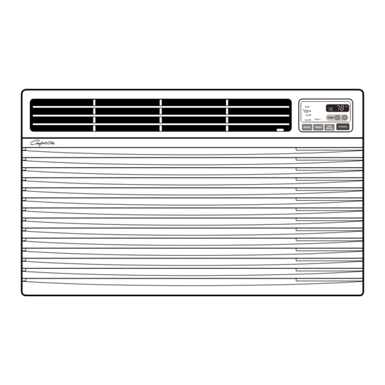
1.4 FEATURES • Designed for cooling only. • Side air-intake, side cooled-air discharge. • Powerful and quiet cooling. • Built in adjustable THERMISTOR and THERMOSTAT. • Top-down chassis for the simple installation and service. • Washable one-touch filter. • Compact size. 1.5 CONTROL LOCATIONS 1.5.1 COOLING ONLY MODEL •... -
Page 5: Disassembly Instructions
2. DISASSEMBLY INSTRUCTIONS — Prior to disassembling the unit, make sure that the POWER is off and the power cord is unplugged from the wall receptacle. 2.1 MECHANICAL PARTS 2.1.1 FRONT GRILLE 1. Open the inlet grille downward. 2. Remove the screw which fastens the front grille. 3. -
Page 6: Air Handling Parts
2.2 AIR HANDLING PARTS 2.2.1 ORIFICE, AND TURBO FAN 1. Remove the front grille. (Refer to section 2.1.1) 2. Remove the cabinet. (Refer to section 2.1.2) 3. Remove the 2 screws which fasten the evaporator at the left side and the right side. (See Fig. -
Page 7: Shroud
2.2.3 SHROUD 1. Remove the fan. (Refer to section 2.2.2) 2. Remove the shroud. (See Fig. 9) 3. Re-install the components by referring to the removal procedures, above. 2.3 ELECTRICAL PARTS 2.3.1 MOTOR 1. Remove the cabinet. (Refer to section 2.1.2) Figure 9 2. -
Page 8: Power Cord
2.3.4 POWER CORD 1. Remove the control box. (Refer to section 2.1.3) 2. Unfold the control box. (Refer to section 2.3.3) 3. Disconnect the grounding screw from the Base pan. 4. Disconnect 2 receptacles. 5. Remove a screw which fastens the clip cord. 6. -
Page 9: Refrigeration Cycle
2.4 REFRIGERATION CYCLE CAUTION Discharge the refrigerant system using a Freon Recovery System. If there is no valve to attach the recovery system, install one (such as a WATCO A-1) before venting the Freon . Leave the valve in place after servicing the system. - Page 10 NOTES — Replacement of the refrigeration cycle. 1. When replacing the refrigeration cycle, be sure to 6. Recharge as follows : discharge the refrigerant system using a Freon 1) Refrigeration cycle systems are charged from the recovery System. High-side. If the total charge cannot be put If there is no valve to attach the recovery system, in the High-side, the balance will be put in the install one (such as a WATCO A-1) before venting...
- Page 11 Equipment needed: Vacuum pump, Charging cylinder, Manifold gauge, Brazing equipment. Pinch-off tool capable of making a vapor-proof seal, Leak detector, Tubing cutter, Hand Tools to remove components, Service valve. Figure 17A-Pulling Vacuum Figure 17B-Charging —11—...
-
Page 12: Installation
3. INSTALLATION 3.1 INSTALLATION REQUIREMENTS INSTALLATION HARDWARE If you use an existing wall sleeve, you should measure its dimensions. Install the new air conditioner according to these installation instructions to achieve the best performance. All wall sleeves 2 Size options used to mount the new air conditioner must be in good structural condition and have a compatible rear grille in order to securely attach the new air conditioner. -
Page 13: Installation
3.2 INSTALLATION NOTE: All wall sleeves used to mount the new Air Conditioner must be in sound structural condition and have a CAUTION rear grille that securely attaches to sleeve, or rear flange that serves as a stop for the Air Conditioner. Installing the FRIEDRICH USC sleeve ensures Remove old air conditioner from existing wall sleeve. -
Page 14: Procedurea
PROCEDURE Install the new unit into the wall sleeve. If you are using the new sleeve (optionally supplied with your unit),skip to step 3. Toassembletrim,tpthetabofeachpiece Otherwise, install the plastic grille from the kit. into the slot of the other piece as shown below. Cut the plastic grille to 25-1/2"... -
Page 15: Procedure B
Remove the backing from the Vertical Insulation PROCEDURE B strip 15 and attach that to the Redirect the louvers at the back of the wall inside right of the sleeve as shown below. sleeve to 60° angle as shown in the FIG 24. The Remove the backing from the Around Insulation use of pliers is recommended. -
Page 16: Front
PROCEDURE B CONTINUED Remove the backing from the support blocks and attach them to the inside of the wall sleeve as shown FIG 29. Slide the baffle into slots of the support blocks. " Wall Wall Baffle Sleeve Front Support Block FIG. -
Page 17: Procedure C
3.5 PROCEDURE C Remove the backing from the Horizontal Insulation strip 7 / 32 3 / 8 3 / 16 and attach that to the inside right of the Redirect the louvers at the back of the wall sleeve to 60° sleeve as shown below. - Page 18 PROCEDURE C CONTINUED CAUTION To achieve rearward slope for unit draining, • Air conditioners covered in this manual pose an remove the backing from the 11 " shim 13 / 16 excessive weight hazard. Two or more people are strips and attach them as shown below in Fig. 37.
-
Page 19: Outside Dimensions
4. TROUBLESHOOTING GUIDE 4.1 OUTSIDE DIMENSIONS 24" " (499mm) (610mm) Cool F1 LOW Energy F2 MED F3 HIGH Saver TEMP Timer MODE TIMER POWER SPEED 4.2 PIPING SYSTEM CONDENSER COILS CAPILLARY TUBE MOTOR COMPRESSOR TURBO FAN EVAPORATOR COILS Following is a brief description of the important components and their functions in the refrigeration system. Refer to Fig. -
Page 20: Troubleshooting Guide
4.3 TROUBLESHOOTING GUIDE In general, possible trouble is classified in two causes. The one is called Starting Failure which is caused from an electrical defect, and the other is Ineffective Air Conditioning caused by a defect in the refrigeration circuit and improper application. Unit is running but cooling is ineffective Ineffective Cooling Check cold air circulation... - Page 21 Fails to Start Check power source. Check circuit breaker and fuse. Check control switch Gas leakage at feeler bulb setting. of thermostat Check control switch. Only compressor fails to Only fan fails to start. start. Improper wiring. Drop in power voltage. Improper thermostat setting Defect of fan motor capacitor.
- Page 22 COMPLAINT CAUSE REMEDY Fan motor will not run. No power Check voltage at outlet. Correct if none. Power supply cord Check voltage to rotary switch. If none, check power supply cord. Replace cord if circuit is open. Rotary switch Check switch continuity. Refer to wiring diagram for terminal identification.
-
Page 23: Room Air Conditioner Voltage Limits
COMPLAINT CAUSE REMEDY Compressor will not run, Voltage Check voltage. See the limits on the preceding. but fan motor runs. page. If not within limits, call an electrician. Wiring Check the wire connections, if loose, repair or replace the terminal. If wires are off, refer to wiring diagram for identification, and replace. - Page 24 REMEDY COMPLAINT CAUSE Compressor cycles Voltage Check the voltage. See the limits on the preced- on overload. ing page. If not within limits, call an electrician. Overload Check overload, if externally mounted. Replace if open. (If the compressor temperature is high, remove the overload, cool, and retest.) Fan motor If not running, determine the cause.
-
Page 25: Schematic Diagram
5. SCHEMATIC DIAGRAM 5.1 CIRCUIT DIAGRAM • MODEL : BG-103A —25—... -
Page 26: Exploded View
6. EXPLODED VIEW • MODEL: BG-103A 132100 152302 147581 147582A 135303 147582B 131400 149980 135312 359012 W48602 559011 354210 435300A 346811 435300 349480 352380 554031 349600 731273 130410 264110 268711B 249950 567480 552102 352115 567502 268711A 35211A 554160 W0CZZ 550140... -
Page 27: Replacement Parts List
7. REPLACEMENT PARTS LIST MODEL: BG-103A LOCATION PART NO. DESCRIPTION REMARK 130410 3041A10064C BASE ASSEMBLY,SINGLE 131400 3090A20017D CABINET 135303 3530A10272A GRILLE,INLET 135312 3531A18004D GRILLE ASSEMBLY,FRONT 147581 4758A20058A LOUVER,HORIZONTAL 147582A 4758A30045A LOUVER,VERTICAL 147582B 4758A30045B LOUVER,VERTICAL 149980 4998A20003A SHROUD 237200 3720A20251A PANEL,CONTROL... - Page 28 Specifications and performance data subject to change without notice. HEAT CONTROLLER, INC. 1900 WELLWORTH AVENUE • JACKSON, MICHIGAN 49203 THE QUALITY LEADER IN CONDITIONING AIR P/No.:3828A20294W Printed in Korea...