Table of Contents
Advertisement
Advertisement
Table of Contents

Related Manuals for Garmin Fishfinder 100


Summary of Contents for Garmin Fishfinder 100
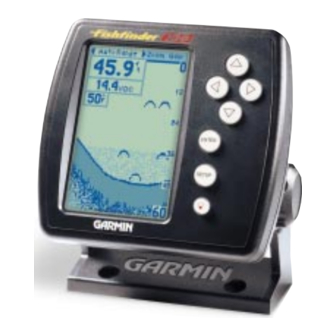
- Page 1 Fishfinder 100 owner’s manual...
- Page 2 Visit the GARMIN website (www.garmin.com) for current updates and supplemental information concerning the use and operation of this and other GARMIN products. GARMIN and Fishfinder 100 are registered trademarks of GARMIN Corporation and may not be used without the express permission of GARMIN Corporation.
-
Page 3: Customer Service
If you encounter a problem, or just have a question, contact or Product Support Department at 913-397-8200, Monday — Friday 8:00 a.m. to 5:00 p.m. Central Time. Enjoy you new Fishfinder 100 and once again thank you for choosing GARMIN. Introduction... -
Page 4: Limited Warranty
GARMIN Corporation warrants this product to be free from defects in materials and manufacture for one year from the date of purchase. GARMIN will, at its sole option, repair or replace any components that fail in normal use. Such repairs or replacement will be made at no charge to the customer for parts or labor. -
Page 5: Packaging And Accessories
The Fishfinder 100 Standard Package contains the following items: • Fishfinder 100 • Surface/Flush Mount Kit • Wiring Adapter Cable • Owner’ s Manual • Quick Reference Guide • *Transom Mount Transducer (w/depth/temp) * Optional Optional Transducers: 010-10251-00 Trolling Motor Mount Adapter... -
Page 6: Table Of Contents
Introduction ... i-viii Customer Service ... i Limited Warranty ... ii Introduction Packaging and Accessories ... iii Unit Display ... vi Installation ... 1-9 Table of Contents Selecting A Transducer ... 1 Transom Mount Installation ... 2 In-hull Installation ... 3 Trolling Motor Installation ... - Page 7 Transducer Coverage ... 29 Understanding the Chart ... 30 Whiteline ... 31 Thermoclines ... 32 Simulator Mode ... 33 Appendix ... 28-33 Appendix A—Specfications ... 34 Appendix B—Alarm Messages and Icons ... 35 Appendix C—Fishfinder 100 Portable ... 36-37 Appendix D—Index ... 38-...
- Page 8 Introduction What can the Fishfinder 100 Display? The Fishfinder 100 is able to display a variety of useful information about the underwater environment. Below are a few things the unit will help you see. The unit displays water depth and can provide a warning for shallow or deep-water conditions.
-
Page 9: Installation
Included in the Optional Package is a 20° cone angle, temperature sensing, transom mount transducer. This transducer provides good all- around performance. A variety of optional transducers are available from your local dealer or GARMIN. Installation Selecting a Transducer Wide cone angle... -
Page 10: Transom Mount Installation
Proper transducer installation is key to getting the best performance from your new unit. If the transducer lead is too short, extension cables are available from you GARMIN dealer. DO NOT cut the transducer lead, this will void your warranty. -
Page 11: In-Hull Installation
In-hull Installation The 010-10224-00 transducer is designed to be mounted inside a fiberglass hull. The standard plastic transom mount transducer can also be mounted in this fashion using this method. If using a temperature sensing transducer, the temperature displayed will reflect the hull temperature. Selecting a Location 1. -
Page 12: Trolling Motor Installation
Installation Mounting the Transducer Cable Ties Worm Gear Clamp Band Slide clamp band through slots on transducer Trolling Motor Installation Included in the 010-10251-00 transducer kit you should have: 1. Worm Gear Clamp 2. Cable Ties 3. Transducer Mounting the Transducer: 1. -
Page 13: Wiring Harness Installation
Wiring Harness Installation The Fishfinder 100 comes with a wiring harness that connects the unit to power and the transducer with one easy-to-remove connection. Make sure the wiring harness will reach the unit before beginning installation. If it is necessary to extend the power/data wires, use a wire of compa- rable size and keep your extension as short as possible. -
Page 14: Installing The Wiring Harness
Make sure the 2-Amp in-line fuse supplied with the unit is installed. The Fishfinder 100 can be connected to another piece of NMEA compatible electronic equipment. If equipped with a capable transducer, the Fishfinder 100 sends depth, temperature and speed information that could be displayed on another device. -
Page 15: Display Installation (Surface Mount)
Display Installation (Surface Mount) The Fishfinder 100 can be mounted to a flat surface using the supplied Surface Mounting Bracket. Surface Mounting the Display: 1. Position the Surface Mount in the desired location. Leave approximately 2'’ behind the unit for cable clearance. -
Page 16: Display Installation (Flush Mount)
Installing the Display Pull bracket down until cam lobe contacts surface Display Installation (Flush Mount) The Fishfinder 100 can be mounted flush against the dash or electron- ics rack that is no more than 1/4” thick. Flush Mounting the Display: 1. -
Page 17: Testing The Installation
While it is possible to perform some checks with the boat trailered, to properly test the installation the boat should be in the water. Press the Power button and the Fishfinder 100 should power on. If the unit fails to power on, verify that the wiring adapter is seated properly in the back of the unit, the Red and Black wires are connected to the correct polarity, and that the 2-Amp fuse is installed and not blown. -
Page 18: Unit Operation
Unit Operation Keypad Function The Arrows Keys are used to select items on the Adjustment Bar and Setup menu and to change field data. The Enter key is used to activate/deactivate Adjustment Bar and Setup Menu data fields for review or change The Setup key is used to activate/deactivate Setup Menu. - Page 19 Depth, Battery Voltage, Water Temperature, and Speed Over Water. To provide data on Water Temperature and Speed Over Water, the Fishfinder 100 requires a transducer capable of producing the particular data. The Depth Scale and the Flasher Function are displayed from top to bottom along the right side of the display.
-
Page 20: Using The Adjustment Bar
Unit Operation The Adjustment Bar Current Setting Adjustment List Using the Adjustment Bar The Adjustment Bar allows direct access to the settings most commonly changed while using the unit. These include the depth Range, Zoom setting, and the Gain (sensitivity) of the unit. Place the highlight (white bar) over the desired selection using the RIGHT or LEFT Arrow key and the current setting will be displayed in the highlight. -
Page 21: Zoom
Zoom The Zoom Adjustment is used to quickly select a display zoom scale. To change the zoom scale: 1. Highlight ‘Zoom’ on the Adjustment Bar. 2. Using the UP or DOWN Arrow, select the desired display zoom level. When a scale other than ‘No Zoom’ is selected, the Adjustment Bar will display a new selection labeled View. -
Page 22: Gain
Unit Operation The Adjustment Bar Minimum Gain Gain The Gain Adjustment allows the user to control the sensitivity of the unit’ s receiver. This provides some flexibility in what is seen on the display. To see more detail, increase the receiver sensitivity by selecting a higher gain (+). -
Page 23: Chart
Setup Menu The Setup Menu contains the unit settings that should not require frequent change. The Setup Menu is divided into eight tabs Chart, Tools, Numbers, Alarms, System, Calibrations, Units, and Memory . Each tab will be described in more detail in this section. To enter and exit the Setup Menu, press the SETUP button on the face of the unit. -
Page 24: Setup Menu
2. Highlight the ‘Scroll Speed’ selection field and press ENTER. 3. Choose ‘Fast’, ‘Medium’, ‘Slow’ or ‘Pause’, press ENTER to accept the selection. If you are using the Fishfinder 100 on the portable case battery power, slowing the scroll rate will help to conserve your battery. -
Page 25: Scale
Scale The depth ‘Scale’ is displayed vertically along the right side of the chart. The depth ‘Scale’ can be configured to display four different ways: as an ‘Overlay’, in the ‘Corners’, with ‘Basic’ or ‘No Scale’. To Change the Scale Setting: 1. -
Page 26: Tools
Unit Operation Setup Menu/Tools Tools Tab Noise Reject Selections Tools The Tools tab contains the ‘Noise Reject’, ‘Flasher’, and ‘Simulator’ tools. The ‘Noise Reject’ and ‘Flasher’ tools are used to enhance the chart and help in identifying and providing information about an underwater return. -
Page 27: Flasher
Simulator The ‘Simulator’ tool allows you to select a transducer type for use with the Fishfinder 100’ s built in simulator. These choices allow the simulator to more accurately depict actual operation of the unit. For details on using the simulator see page 33. -
Page 28: Numbers
3. Choose ‘Normal’ or ‘Large’, press ENTER to accept the selection. Battery Voltage The Fishfinder 100 can display the current battery voltage on the chart. To Show or Hide the Battery Voltage Display Field: 1. Highlight the ‘NUM’ tab on the Setup Menu. -
Page 29: Temperature
3. Choose ‘Auto’, ‘Show’ or ‘Hide’, press ENTER to accept the selection. Speed The Fishfinder 100 can display the boat’ s ‘Speed’ Over Water when equipped with a speed capable transducer. The unit has the ability to automatically sense when a capable transducer is connected and display speed. -
Page 30: Alarms
Alarms The ‘Alarm’ tab allows you to activate and configure the four alarms available in the Fishfinder 100. To access the ‘Alarm’ tab place the highlight over it using the arrow keys. See page 35 for alarm icons and messages. -
Page 31: Deep Water
Deep Water The ‘Deep Water’ Alarm can be set to sound a warning at a depth determined by the user. Before the unit will sound a warning the alarm must be activated. Activating/Deactivating the Deep Water Alarm: 1. Highlight the ‘Alarm’ tab on the Setup Menu. 2. -
Page 32: System
3. Choose ‘Off’, ‘Alarms’, or ‘Key & Alarms’, press ENTER to accept the setting. NMEA Output The Fishfinder 100 has the ability to output information about Depth, Speed, and Water Temp for display on another NMEA-compatible device. To Activate/Deactivate the NMEA Output: 1. -
Page 33: Calibration
The ‘Cal’ (Calibration) tab contains calibrations fields for ‘Keel Offset’, and ‘Water Type’ (salt or fresh). These calibrations help to ensure the Fishfinder 100 will provide the most accurate readings at all times. To access the ‘Calibration’ tab, use the arrow keys to highlight it. -
Page 34: Units
Unit Operation Setup Menu/Units Depth Selections Temperature Selections Speed Selections Units The ‘Units’ tab contains settings for ‘Depth’, ‘Temperature’ and ‘Speed’. To access the ‘Units’ tab, use the arrow keys to highlight it. Depth The ‘Depth’ field can be configured to display in Feet (ft), Meters (mt) or Fathoms (fa). -
Page 35: Memory
To access the ‘Memory’ tab, use the arrow keys to highlight it. Remember The Fishfinder 100 can be set to remember All of the unit settings including the Adjustment Bar or the items in Setup Only. To Select a Memory Setting: 1. -
Page 36: Understanding Sonar
If you are familiar with sonar, and can determine what is on the chart, this section may not be for you. This section is intended to help the novice user gain some understanding of how the Fishfinder 100 operates and how it can help improve their fishing productivity. -
Page 37: On The Water
Transducer Coverage The area covered by the transmitted sound waves is determined by the cone angle of the transducer and the water depth. Using Garmin’ s standard 20° transducer, the coverage is approximately 1/3rd of the water depth. As shown in Example 1, the coverage area at a 30 foot depth is approximately a 10 foot diameter circle. -
Page 38: Understanding The Chart
On the Water Understanding the Chart Branches Enlarged Transducer Fish View Remember that the Fishfinder displays a 2D picture of the underwater environment. The fish and tree could be located anywhere in the coverage area at that slice of time. Understanding the Chart It is important to understand that the unit does not display a 3-D representation of the underwater environment. -
Page 39: Whiteline
Whiteline The Fishfinder 100 can help you to determine if the bottom is hard or soft. When the sonar soundwaves are reflected back by the bottom, a hard bottom will return a stronger signal than a soft bottom. The stronger bottom return, the wider the bottom layer is displayed. -
Page 40: Thermoclines
On the Water Understanding the Chart Thermoclines One of the unique features offered by GARMIN is See-Thru™ technology. See-Thru™ technology allows the Fishfinder 100 to see through thermoclines and helps locate fish where they live, and fish love the thermocline. -
Page 41: Simulator Mode
The message will be replaced by the simulator mode icon in the lower left corner of the chart. While in the simulator mode, the unit will display a random bottom scene and the Fishfinder 100 can be controlled just as if it were on the water. -
Page 42: Appendix A-Specfications
Specifications Physical Case: Fully Gasketed, high-impact plastic alloy Display: 3.3” x 2” (8.3 x 5 cm) 160 H x 100 W pixels Size: 4.9” H x 5.3” W x 2.7” D (12.5 x 13.5 x 6.9 cm) Weight: 13 oz. -
Page 43: Appendix B-Alarm Messages And Icons
Alarm Messages and Icons The Fishfinder 100 displays a message when an alarm is tripped. To clear the message press the ENTER key. If the ENTER key is not pressed, the unit will automatically remove most messages after 10 seconds and display a reminder icon in the lower left corner of the chart until the alarm is no longer valid. -
Page 44: Appendix C-Fishfinder 100 Portable
The Portable Case is designed for rugged use and provides storage for the Battery Pack and the Portable Suction Cup Transducer and a mount for the Fishfinder 100. The case is water resistant but is not designed to float in the event it should go overboard. -
Page 45: Appendix C—Fishfinder 100 Portable
Batteries The Fishfinder 100 Portable comes with a D-Cell battery pack. Eight D-Cell Alkaline batteries will provide approximately 20 hours of continu- ous operation. You have the option of purchasing a 12 Volt Rechargeable Gel-Cell Battery for the portable case. - Page 46 Depth ... 26 Display ... vi Display Installation ... 7 Enter Key ... 10 Factory Setup ... 27 Fish Alarm ... 22 Fish Symbols ... 15 Fishfinder 100 Portable ... 36 Flasher ... 19 Flush Mount ... 8 Gain ... 14...
- Page 47 In-hull Installation ... 3 Installing the Display ... 7 Appendix D Keel Offset ... 25 Keypad ... 10 Index Limited Warranty ... i Memory ... 27 Messages ... 35 NMEA Output ... 24 Noise Reject ... 18 Number Size ... 20 Numbers ...
- Page 48 Software Version ... 27 Specifications ... 34 Appendix D Speed 2 ... 1, 26 Suction Cup Transducer ... 36 System ... 24 Index Table of Contents ... vi Temperature ... 21, 26 Testing the Installation ... 9 Tools ... 18 Transducers ...
- Page 49 © 1999 GARMIN Corporation GARMIN International, Inc. 1200 East 151st Street, Olathe, Kansas 66062, U.S.A. GARMIN (Europe) Ltd. Unit 5, The Quadrangle, Abbey Park Industrial Estate, Romsey, SO51 9AQ, U.K. GARMIN (Asia) Corporation No. 68, Jangshu 2 Road, Shijr, Taipei County, Taiwan www.garmin.com...