
Related Manuals for Liebert Liebert iCOM


Summary of Contents for Liebert Liebert iCOM
- Page 1 Liebert iCOM ® ™ User Manual - Intelligent Communications & Monitoring Precision Cooling For Business-Critical Continuity™...
-
Page 3: Table Of Contents
Navigating Through the Liebert iCOM Menus ........ - Page 4 Wiring a Liebert iCOM U2U Network ........
- Page 5 Figure 29 Liebert iCOM input-output control board ........
- Page 6 Table 11 Ports available for connecting Liebert iCOM control devices......47 Table 12 Setpoints parameters .
-
Page 7: Introduction
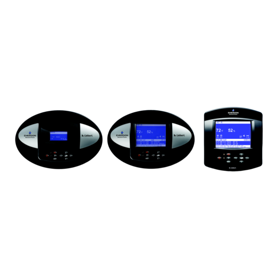
• The Liebert iCOM with large display has a 320 x 240 dot matrix screen that shows up to 16 menu icons at a time, as well as descriptive text. This display can be used to control a single cool- ing unit or any cooling unit on a network, regardless of how it is connected—either integrated into... -
Page 8: Liebert Icom Display Components And Functions
On/Off Key Escape Key NOTE The Help key may be pressed at any time for a brief explanation of what is being viewed. Liebert iCOM Display Components and Functions OMPONENTS AND E S C Alarm Key Help Key... -
Page 9: Table 1 Keyboard Icons And Functions
Decrease Key (Down Arrow) Left and Right Arrow Keys Upper LED Lower LED Liebert iCOM Display Components and Functions Function Controls the operational state of the cooling unit. Silences an alarm. Accesses integrated help menus. Returns to the previous display view. -
Page 10: Figure 3 Status Menu, Large Display, Graphical View
Reading Evaporator Fan Speed Percent Cooling Free-Cooling Percentage Next Maintenance Date and Time Figure 4 Liebert iCOM default screen symbols hot water Liebert iCOM Display Components and Functions Temperature Humidity Setpoint Setpoint cooling freecooling electric heat dehumidification Humidity Sensor Reading... -
Page 11: Navigating Through The Liebert Icom Menus
Once in a Submenu, a list of parameters is displayed. Press the enter key and use the up and down arrow keys to scroll through the parameters one-by-one. Pressing the Esc key will go back a level. Figure 5 shows the Liebert iCOM control menus for a small display. -
Page 12: Entering A Password
Setpoints Event Log Graphics Set Alarms Sensor Data Display Setup Total Run Hours Sleep Mode Service Info Active Alarms Liebert iCOM Display Components and Functions Status Menu Unit 1 View Service Menu Password Setpoints Standby Wellness Diagnostics Set Alarms Calibration... -
Page 13: Figure 6 Menu Tree-Large Display, Stand-Alone
View Network Set Alarms Sensor Data Active Alarms Display Setup Total Run Hours Sleep Mode Service Contact Info Liebert iCOM Display Components and Functions Status Menu – System View Status Menu Unit 1 View Service Menu Unit 1 Password Setpoints... -
Page 14: Viewing Multiple Units With A Networked Large Display
View Network Set Alarms Sensor Data Active Alarms Display Setup Total Run Hours Sleep Mode Service Contact Info Liebert iCOM Display Components and Functions Status Menu – System View (Networked Large Display Only) Service Menu Unit # Password Setpoints Unit Diary... -
Page 15: Figure 8 User Menu Icons
Active Alarms ACTIVE ALARMS Display Setup 1234h Total Run Hours Liebert iCOM Display Components and Functions Description View and change temperature and humidity setpoints Displays the various part numbers of the components/parts in the cooling unit Contains last 400 events... -
Page 16: Table 11 Table
Table 2 User menu icons (continued) Icon Name Sleep Mode Service Contact Info Liebert iCOM Display Components and Functions Description Allows setback settings for non-peak operation Contains key contact information for local service, including names and phone numbers Available On Display Small &... -
Page 17: Figure 9 Service Menu Icons
Calibration/Setup NETWORK System/Network Setup Options Setup Service Contact Info Liebert iCOM Display Components and Functions Service Menu password: 5010 Description To view and change temperature and humidity setpoints Shows all entered program changes and maintenance performed on the unit Allows lead/lag setup when multiple units are connected... -
Page 18: Operation
PERATION The Liebert iCOM display for your Liebert cooling unit features an easy-to-use, menu-driven liquid crystal display (LCD). All unit settings and parameters can be viewed and adjusted through three menus: User, Service and Advanced. All active alarms are displayed on the LCD and annunciated. -
Page 19: Chilled Water Units With Variable Speed Motor
• Manual operation: when set to Manual, the speed of the VSD motor follows user input as set either locally at the cooling unit's Liebert iCOM display (under VSD Setpoint in Service Menu, Setpoints) or remotely using Modbus BMS signal with an optional Liebert IntelliSlot... -
Page 20: General Compressor Requirements
3.1.3 General Compressor Requirements Low-Pressure Time Delay When the compressor starts, the low-pressure input is ignored for a selected period of time based on the setting of the Low Pressure Alarm Delay (Service Menu, Options Setup). This time is usually set to 3 minutes on air-cooled units, and to 0 or 1 minute on water cooled units. -
Page 21: Compressor Timing-Units With Two Compressors
Digital Scroll High Temperature A protective maximum operating compressor temperature limit is imposed on units with digital scroll compressor(s) with thermistor. Once the digital scroll temperature reaches the maximum tempera- ture threshold, the compressor will be locked out for at least 30 minutes and an alarm will be annun- ciated. -
Page 22: Motorized Ball Valve In Digital Scroll Units
Each compressor has one motorized ball valve that is driven by the analog output of the Liebert iCOM control board based on pressure. If there is a call for cooling, the compressor start is delayed by a 30- second timer. -
Page 23: Temperature Control-Single Source Cooling (No Extra Cooling Coil)
Temperature Control—Single Source Cooling (No Extra Cooling Coil) 3.3.1 Temperature Proportional Band The control uses the temperature proportional band to determine which operation to perform (cool- ing/heating) and how intensely to perform it. The Temperature Proportional Band is a user-defined range that is divided into two equal parts for cooling and heating. -
Page 24: Compressor Control
3.3.2 Compressor Control Depending on the type of Liebert air conditioning unit you have your unit may contain one or two compressors with or without unloaders. Compressor Proportional Bands One Single-Step Compressor Without Unloaders—One-Step One single-step compressor, Cool 1, is started at 100% call for cooling from the temperature propor- tional band and stopped at 0% (see Figure 12). -
Page 25: Figure 14 Two Compressors With Unloaders (Four-Step)
Two Compressors With Unloaders—Four-Step The first two-step compressor is started unloaded at 33% calculated output from the temperature pro- portional band and stopped at 17%. At 80% Compressor 1 will be loaded, at 70% unloaded. The second compressor starts unloaded at 63% and stops at 47%. At 100%, Compressor 2 will be loaded, at 90% unloaded (see Figure 14). -
Page 26: Figure 15 Digital Scroll Capacity Modulation, 10-100% Variable
Digital Scroll Compressors A compressor with a suction cutoff unloader can only modulate its capacity between two distinct lev- els: fully loaded and half loaded. A digital scroll compressor can modulate its capacity anywhere between 10-100%. This variable capacity modulation allows cooling units to control an environment more precisely. -
Page 27: Chilled Water Control
3.3.3 Chilled Water Control The chilled water control valve is adjusted proportionally as the temperature control varies the requirement for cooling from 0% to 100%. Units with the optional variable speed drive (VSD) control the fan speed in a similar manner, except that the minimum fan speed is 60% when the cooling requirement is less than 60%. -
Page 28: Figure 18 Second Cooling Source And Compressorized Cooling
The Value setting is the factory default setting on free-cooling and dual cooling units. If the tempera- ture difference between the second source cooling fluid parameter, Free-cooling Fluid Temperature (User Menu, Sensor Data) and room air is equal to or greater than the adjustable DT Between Room Air / FC Fluid (Service Menu, Setpoints) value, then the second source cooling fluid will be used to provide at least partial cooling (delta T between room and glycol = true). -
Page 29: Temperature Control-Reheat
™ GLYCOOL Cooling—Free-Cooling When GLYCOOL cooling is available, the temperature control will calculate a total cooling require- ment of 200% rather than 100%. Assuming that full GLYCOOL capacity is available, the GLYCOOL valve opens proportionally as the requirement for cooling rises from 0 to 100%. If more than 100% cooling is required, then the compressors are activated at 150% and 200% respectively (133%, 163%, 180% and 200% for a four-step system). -
Page 30: Figure 19 Three-Stage Heating
Figure 19 Three-stage heating Temp Setpoint: 70°F Proportional Band: 8°F Deadband: 2°F -100 % Heating Decreasing Temperature Heat 3 Heat 2 Heat 1 Heat 3 Heat 2 Heat 1 ½ Proportional Band ½ Dead- band Heating Operation... -
Page 31: Scr Reheat
3.5.2 SCR Reheat SCR reheat is a type of electric reheat that provides tighter temperature control than staged electric reheat. SCR reheat capacity modulation is achieved by pulsing the reheat On and Off. Full capacity is achieved by constantly energizing the reheat. Units equipped with SCR reheat can operate in Tight or Standard mode. -
Page 32: Figure 21 Two Single-Step Compressors With Scr Reheat Set To Standard Mode
Standard Mode In Standard mode, the SCR reheat operates only when the Temperature Proportional Band calls for heating. SCR reheat output is adjusted proportionally as the Temperature Proportional Band varies the requirement for heating from 0% to -100%. Compressors operate only when there is a call for cool- ing as described in 3.3.2 - Compressor Control. -
Page 33: Humidity Control
Humidity Control The control uses the humidity proportional band to determine which operation to perform (dehumidi- fication/humidification) and how intensely to perform it. The Humidity Proportional Band is a user defined range that is divided into two equal parts for dehumidifying and humidifying. The Humidity Setpoint is located between these two equal parts. -
Page 34: Humidification
3.6.1 Humidification Infrared Humidifier There are two types of infrared humidifiers: small pan (IFS) and large pan (IFL). The operating mode of each is similar, however, some of the variables or timings differ. Infrared humidifiers are started at 100% humidification request, and stopped at 0%. Infrared humid- ifiers cannot be driven in proportional mode. -
Page 35: Dehumidification
3.6.2 Dehumidification The Dehumidification Enable parameter (Service Menu, Options Setup) allows for enabling/disabling the dehumidification function. A call for dehumidification is calculated in the same way as a cooling request. The components (valves, compressors) will follow this dehumidification request as soon as it is higher than the request for cooling. -
Page 36: Control Types
3.7.1 Temperature and Humidity Control Types The Liebert iCOM control has four Temperature and Humidity Control Types: Proportional, PI and Intelligent. Each control type affects the timing and intensity of the cooling/heating and humidify- ing/dehumidifying operations. The Control Type parameter is in the Service menu under Setpoints. -
Page 37: Humidity Sensor Reading Control Types
3.7.2 Humidity Sensor Reading Control Types The Liebert iCOM control has three humidity sensor control types: Relative, Compensated and Pre- dictive. The humidity sensor control adjusts how the Temperature and Humidity Control determines the percent requirement for humidification/dehumidification. The humidity sensor control type parameter, Humidity Control Type, is in both the User and Service menus under Setpoints. -
Page 38: Supply Limit-Optional
3.7.3 Supply Limit—Optional Chilled water units may be ordered with an additional sensor for monitoring the supply air tempera- ture. This sensor maintains the minimum air temperature under a raised floor to help prevent con- densation from forming. In order to avoid supply temperatures that are too low, the Supply Limit can influence the opening of three-point or analog actuators or the output of analog values. -
Page 39: User Inputs / Customer Inputs
3.7.5 User Inputs / Customer Inputs The user can connect and specify up to four inputs depending on unit configuration. The user inputs/customer inputs are digital inputs that influence the operating mode of the unit depending on the selection. The customer input configuration settings are in the Service menu under Set Alarms, Screen 2 of 7. -
Page 40: Event Types And Properties
Event Types and Properties Liebert iCOM events are used to inform the user of cooling unit operational status. All events are recorded in the Event Log, which is in the User Menu. The user can change the type (alarm, warn, message) and time delay of some events and can also enable or disable some events. -
Page 41: Table 21 Table
Table 8 Possible event settings—some events not available in all units Event MAIN FAN OVERLOAD LOSS OF AIRFLOW CLOGGED FILTERS HIGH ROOM TEMP LOW ROOM TEMP HIGH ROOM HUM LOW ROOM HUM HIGH TEMP SENSOR A LOW TEMP SENSOR A HIGH HUM SENSOR A LOW HUM SENSOR A COMP 1 OVERLOAD... -
Page 42: Possible Event Notifications
OTIFICATIONS Table 9 lists alarms and warnings that may occur in a cooling unit. When any of these occur, they will appear on the Liebert iCOM Status menu and will be recorded in the Liebert iCOM Event log. Table 9 Event notifications—large or small display... -
Page 43: Next Maintenance Calculation
To calculate wellness, Liebert iCOM keeps a running total of component working hours and the num- ber of times it has been started. Liebert iCOM relates that data to the optimum/maximum starts per hour. Accordingly, Liebert iCOM will increase or decrease the time before the next service call will be needed. - Page 44 Parameters for Next Maintenance Calculation General Maintenance Settings • Maintenance Frequency—can be set as one to 12 months or to zero, which disables mainte- nance calculation • Max. Bonus—increases the time to next maintenance with the set value, if all components run optimally (number of starts, average running time) •...
-
Page 45: Teamwork
Unit-2-Unit (U2U) Communications via a private network will allow the following functions to be placed into operation when the requirement exists. The user must install the correct hardware (see 5.0 - Installing a Liebert iCOM Unit-to-Unit Network) and properly program the units for the selected functionality. -
Page 46: Figure 23 Teamwork Mode 1 With Two Cooling Units
The number of available units is calculated like: • In non-standby configuration: all units with fan on • In typical standby function (no cascade): all units with fan on • In cascade mode: all units that could operate (no alarm, which forces the unit to switch off, unit not switched off, etc.) NOTE 1. -
Page 47: Teamwork Mode 2
4.1.4 Teamwork Mode 2 Teamwork Mode 2 is designed to prevent units within a group from working against each other or “fighting.” It is best applied in large rooms with unbalanced heat loads. In Teamwork Mode 2, all parameters are shared equal to Mode 1, and Unit #1 averages all of the available unit sensor readings on the network to define whether there is a cooling, heating, dehumidification or humidification request. -
Page 48: Installing A Liebert Icom Unit - To -Unit Network
NSTALLING A IEBERT I Connecting multiple Liebert iCOM-controlled cooling units in an Ethernet Unit-to-Unit (U2U) net- work enables the units to work together to achieve efficient cooling and humidity control of the condi- tioned space. Networking enables setting up the cooling units to exchange data for various modes of operation: •... -
Page 49: Wiring For Unit-To-Unit Communications-U2U
(failed network switch, etc.), all Liebert iCOM-controlled cooling units will continue to operate as independent units. The Liebert iCOM control can support up to 64 nodes on one network. An input/output board, large display, and large wall-mount display are each considered one node. Of the 64 nodes that may be con- nected, no more than 32 may be input/output boards (32 cooling units). -
Page 50: Wiring A Liebert Icom U2U Network
Each cooling unit with a large display requires two straight-through Ethernet cables from a network switch. One cable connects to port P64 on the Liebert iCOM input/output board and the other straight-through cable connects to the female-female coupler provided with the unit. Con- nect the red crossover cable, which is provided with the cooling unit, between the coupler and the P64 port on the back of the large display (see Figure 28). -
Page 51: Figure 25 Wiring A Small Display For Stand-Alone Operation
Microprocessor and I/O Board Unit Electronics Compartment Small Graphics Display On Unit Accent Unit-to-Unit Communications With More Than Two Units 6-Wire Cable iCOM Installing a Liebert iCOM Unit-to-Unit Network 182964 Page 1 Rev. 0 1 Straight-Through Ethernet Cable Connection to P64 Networking Switch To Other Units (64 nodes total;... -
Page 52: Figure 27 Wiring A Large Display For Stand-Alone Operation
Microprocessor and I/O Board Unit Electronics Compartment 8-Wire Crossover P64 P66 P67 Ethernet Cable (Red) U2U CAN CAN Crossover Coupler iCOM Installing a Liebert iCOM Unit-to-Unit Network Liebert- Supplied Crossover Coupler (F-F) 8-Wire Crossover 182964 Page 2 Rev. 0... -
Page 53: Figure 29 Liebert Icom Input-Output Control Board
See the Liebert vNSA user manual, SL-18840, for more details. The number of ports available for connecting Liebert iCOM control devices varies by model as shown in Table 11. Models with a remote large display attached to the front door utilize one of the available Ethernet ports in the Liebert vNSA. -
Page 54: External Communications-Building Management Systems, Liebert Sitescan
12" (305mm) External Communications—Building Management Systems, Liebert SiteScan Liebert iCOM is capable of communicating with external monitoring systems, such as Building Man- agement Systems (BMS), Network Monitoring Systems (NMS), Liebert's SiteScan others. Each Liebert iCOM-controlled cooling unit is equipped with Liebert IntelliSlot plug-in slots for use with optional communication cards: •... -
Page 55: Mounting A Large Display On A Wall
Insert screws in the wall and use the keyhole-shaped holes on the back of the housing 2. Route the factory-supplied power supply cable and field-supplied CAT5 Ethernet cable through the wall to the mounting location for connection to the rear of the Liebert iCOM wall-mount display (see Figure 31). -
Page 56: Figure 31 Liebert Icom Display Dimensions
Figure 31 Liebert iCOM display dimensions 8" (203mm) 8.83" (224mm) FRONT VIEW AC Adapter/Plug 120V/60Hz-12VDC 10ft. (3048mm) routed 12VDC Pwr through wall to back of display housing (provided by Liebert) 1.92" (49mm) 1.4" (36mm) 4.52" (115mm) 1.4" 2.11" (36mm) (54mm) -
Page 57: User Menu Parameters
ARAMETERS User menus report general cooling unit operations and status. The password for the user menu is 1490. The iCOM control firmware is being updated constantly. As a result, the User menu parameter tables in this manual may be slightly different than what is shown on your cooling unit's display. Please check www.liebert.com Table 12... - Page 58 Table 16 Set alarms parameters Function ALARMS Large Display Page 1 of 1 Password Return Sensor Alarms High Return Temperature Low Return Temperature High Return Humidity Low Return Humidity Sensor A Alarms High Temperature Sensor A Low Temperature Sensor A High Humidity Sensor A Low Humidity Sensor A Table 17...
-
Page 59: Table 18 Active Alarms Parameters
Table 17 Sensor data Function Large Display Daily Low Humidity Daily Low Humidity Active Alarms Permits viewing all current, active alarms. Table 18 Active alarms parameters Function ACTIVE Large Display ALARMS Page 1 of 1 Active Alarms Table 19 Display setup parameters Function Large Display Page 1 of 1... - Page 60 Table 20 Total run hours parameters 1234h Function Large Display Page 1 of 1 Actual Hours / Limit Fan Motor(s) Fan Motor(s) Limit Compressor 1 Compressor 1 Limit Compressor 2 Compressor 2 Limit Chilled Water/Free Cool Chilled Water/Free Cool Limit HotGas / HotWater HotGas / HotWater Limit Electric Heater 1...
-
Page 61: Table 22 Service Contacts Parameters
Table 21 Timer parameters—Sleep Mode Function Large Display Timer Mode Type TIME TYP Dead Band DEADBAND Table 22 Service contacts parameters Function Large Display Small Display Page 1 of 1 Address line 1 Address line 1 A+B Address line 2 Address line 2 A+B Address line 3 Address line 3 A+B... -
Page 62: Service Menu Parameters
ERVICE ARAMETERS Service menus allow customized settings for site operations. The password for service menu parame- ters is 5010. The iCOM control firmware is being updated constantly. As a result, the Service menu parameter tables shown in this manual may be slightly different than what is shown on your cooling unit's dis- play. -
Page 63: Table
Table 23 Setpoints parameters °C / °F % RH Function Large Display VSD Setpoint Page 4 of 5 Password VSD Fanspeed VSD Setpoint STD VSD Setpoint MIN VSD Setpoint Dehum VSD Setpoint No Power Page 5 of 5 Password SCR Control Type Start Compressor 1 At Stop Compressor 1 At Compressor 1 Stop Delay... -
Page 64: Table 25
Table 25 Standby settings / lead-lag parameters Function Large Display Page 1 of 1 Password Number of Standby Units Rotation Frequency Rotate At (hour) Rotate At (minute) Rotate By Perform One Rotation Cascade Units Start all Standby Units by HT See 3.9.1 - Calculation of Next Maintenance and Diagnostics for details on these menus. - Page 65 Table 26 Maintenance / wellness settings parameters (continued) Function WELLNESS Large Display Compressor1 Settings (Page 3 of 8) Password Number of Starts Run Hours Average Run Time Starts per Day Best Starts per Day Worst Number of HP Alarms Number of LP Alarms Number of OL Alarms Number of DS HT Alarms Actual Bonus...
- Page 66 Table 26 Maintenance / wellness settings parameters (continued) Function WELLNESS Large Display El. Heater 2 Settings (Page 6 of 8) Password Number of Starts Run Hours Average Run Time Starts per Day Best Starts per Day Worst Number of Alarms Actual Bonus El.
-
Page 67: Table 27 Diagnostics / Service Mode Parameters
Table 27 Diagnostics / service mode parameters Function Large Display SERVICE Page 1 of 7 Password HP 1 Alarm Code HP 2 Alarm Code HT 1 Alarm Counter HT 2 Alarm Counter LP 1 Alarm Code LP 2 Alarm Code Actual LP1 Pressure Actual LP2 Pressure Actual HP1 Pressure... - Page 68 Table 27 Diagnostics / service mode parameters (continued) Function Large Display SERVICE Password Alarm Relay FC Relay 3P Actuator Open 3P Actuator Close BV Control Analog Out 1 Analog Out 2 Analog Out 3 Analog Out 4 Page 5 of 7 Status Remote Shutdown Status Airflow Loss Status Motor Overload...
-
Page 69: Table 28 Set Alarms Parameters
Table 27 Diagnostics / service mode parameters (continued) Function Large Display SERVICE Page 7of 7 Status Humidifier Problem Status DT1 (Outdoor/Glycol) Status DT2 (Glycol/Room) Status DT3 (Room/Setpoint) Status Min CW LWD Value Status LSI Table 28 Set alarms parameters ALARMS Large Display Page 1 of 7 Password... - Page 70 Table 28 Set alarms parameters (continued) Function ALARMS Large Display Page 2 of 7 Password Customer Input 1 Customer Input 1 active when Customer Input 2 Customer Input 2 active when Customer Input 3 Customer Input 3 active when Customer Input 4 Customer Input 4 active when WARNING ACTIVATES ALARM RELAY Reset Disabled Alarms...
- Page 71 Table 28 Set alarms parameters (continued) Function ALARMS Large Display HIGH TEMP SENSOR A LOW TEMP SENSOR A HIGH HUM SENSOR A LOW HUM SENSOR A ENABLE - DISAB MAIN FAN OVERLOAD LOSS OF AIRFLOW CLOGGED FILTERS HIGH ROOM TEMP LOW ROOM TEMP HIGH ROOM HUM LOW ROOM HUM...
- Page 72 Table 28 Set alarms parameters (continued) Function ALARMS Large Display ENABLE - DISAB COMP 1 OVERLOAD COMP 2 OVERLOAD COMP 1 HIGH PRESSURE COMP 2 HIGH PRESSURE COMP 1 LOW PRESSURE COMP 2 LOW PRESSURE COMP 1 PUMPDOWN FAIL COMP 2 PUMPDOWN FAIL DIG SCROLL1 HIGH TEMP DIG SCROLL2 HIGH TEMP EL HEAT HIGH TEMP...
- Page 73 Table 28 Set alarms parameters (continued) Function ALARMS Large Display COND PUMP-HIGH WATER LOSS OF FLOW STBY GLYCOL PUMP ON STANDBY UNIT ON HUMIDIFIER PROBLEM NO CONNECTION w/Unit1 UNIT X DISCONNECTED LOSS OF POWER TYPE WORKING HRS EXCEEDED SMOKE DETECTED WATER UNDER FLOOR COND PUMP-HIGH WATER LOSS OF FLOW...
- Page 74 Table 28 Set alarms parameters (continued) Function ALARMS Large Display REHEAT LOCKOUT HUMIDIFIER LOCKOUT FC LOCKOUT COMPRESSOR(S) LOCKOUT TYPE CUSTOMER INPUT 1 CUSTOMER INPUT 2 CUSTOMER INPUT 3 CUSTOMER INPUT 4 CALL SERVICE HIGH TEMPERATURE LOSS OF AIR BLOWER 1 REHEAT LOCKOUT HUMIDIFIER LOCKOUT FC LOCKOUT...
-
Page 75: Table 29 Sensor Calibration / Setup Parameters
Table 28 Set alarms parameters (continued) ALARMS Large Display TYPE COMP 1 SHORT CYCLE COMP 2 SHORT CYCLE NO POWER CONDENSER 1 FAILURE CONDENSER 2 FAILURE Table 29 Sensor calibration / setup parameters Function + / - Large Display Page 1 of 3 Password Return Temperature Calibrated Return Temperature... -
Page 76: Table 30 System / Network Setup Parameters—Large Display Only
Table 29 Sensor calibration / setup parameters Function + / - Large Display Freecool Sensor PTC or NTC Freecool Sensor Calibrated Freecool Sensor Supply Sensor PTC or NTC Supply Sensor Calibrated Supply Sensor Temperature Sensor C Calibrated Temperature Sensor C Humidity Sensor C Calibrated Humidity Sensor C Table 30... - Page 77 Table 30 System / network setup parameters—large display only NETWORK Function Large Display Netmask Gateway U2U Protocol U2U Address U2U Group Bootloader Variables Bootloader Variables Table 31 Network setup parameters NETWORK Function Read/ Large Display Write Page 1 of 2 (Unit) Password Monitoring Address Monitoring Timeout...
-
Page 78: Table 31 Network Setup Parameters
Table 31 Network setup parameters NETWORK Function Read/ Large Display Write Netmask Gateway U2U Protocol U2U Address U2U Group Bootloader Variables Bootloader Variables Static RAM Static RAM Range Imperial (metric) Netmask Range Gateway Range MAC Range 1-32 1-99 Not Available, Invalid, OK, Changed, Updating No, Save+Reboot Not Available, Invalid, OK,... -
Page 79: Table 32 Options Setup Parameters
Table 32 Options setup parameters Function Large Display Page 1 of 3 Password Compressor Sequence Low Pressure Alarm Delay Electric Stages Hot Water Heat On/Off Total Heat Stages LWD Connected 3P Actuator Runtime 3P Actuator Direction Page 2 of 3 Password Humidification Enabled Infrared Flush Rate... -
Page 80: Table 33 Service Contact Info Parameters
Table 33 Service contact info parameters Function Large Display Small Display Page 1 of 1 Password PASSWORD Country Country Address line 1 Address line 1 Address line 2 Address line 2 Address line 3 Address line 3 Address line 4 Address line 4 Read/ Range... - Page 81 Service Menu Parameters Notes...
- Page 82 Service Menu Parameters...
- Page 84 Embedded Computing Connectivity Embedded Power DC Power Monitoring Business-Critical Continuity, Emerson Network Power and the Emerson Network Power logo are trademarks and service marks of Emerson Electric Co. ©2008 Emerson Electric Co. Technical Support / Service Liebert.monitoring@emerson.com Outside the US: 614-841-6755 upstech@emersonnetworkpower.com...