Table of Contents
Advertisement
Quick Links
Advertisement
Table of Contents

Related Manuals for Furuno FM-2710


Summary of Contents for Furuno FM-2710
- Page 2 9 - 5 2 , A s h i h a r a - c h o , N i s h i n o m i y a , J a p a n Te l e p h o n e : 0 7 9 8 - 6 5 - 2 111 Te l e f a x: 0 7 9 8 - 6 5 - 4 2 0 0...
-
Page 3: Safety Information For The Operator
SAFETY INFORMATION FOR THE OPERATOR WARNING Do not open the cover of the equipment. This equipment uses high volt- age electricity which can shock, burn. Only qualified personnel should work inside the equip- ment. Do not disassemble or modify the equip- ment. - Page 4 SAFETY INFORMATION FOR THE OPERATOR WARNING Only qualified personnel should work inside the equip- ment. This equipment uses high volt- age electricity which can shock, burn, or cause death. Turn off the power at the ship's mains switchboard before beginning the instal- lation.
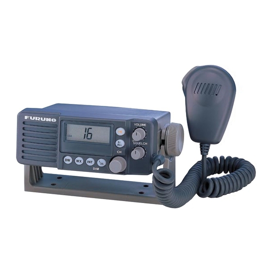
- Page 6 Congratulations on your choice of the FURUNO FM-2710 Marine VHF Radiotelephone. We are confident that you will enjoy many years of trouble-free operation with this fine piece of equipment. For nearly 50 years FURUNO Electric Company has enjoyed an enviable reputation for quality and reli- ability throughout the world.
- Page 7 1-1. Features of the FURUNO FM-2710 ! 25 W RF output from a compact cabinet: may be mounted in any small space. ! Water-resistant structure (CFR-46 FCC Regulation Spec.) ! All VHF channels according to ITU-R Radio Regulations Appendix S 18 and FCC Part 80, plus 10 weather channels (U.S.A.
-
Page 8: Specifications
1-2. Specifications GENERAL 1. Radio Compliance USA Part 80, DOC Cat. V 2. Number of Channels All VHF channels according to ITU-R Radio Regulations Appendix S 18 and FCC Part 80, plus 10 weather channels (U.S.A. and Canada) 3. Supply Voltage 12 VDC nominal -10%, +30% (10.8 - 15.6 VDC) 4. - Page 9 RECEIVER 1. Frequency Range 156.025 to 163.275 MHz 2. AF Output 3 W at 4 ohms load (less than 10% at 1 kHz) 3. Current Drain Less than 250 mA 4. AF Response 6 dB/oct de-emphasis +1/-3 dB from 300 to 3000 Hz 5.
- Page 10 TRANSMITTER 1. Frequency Range 156.025 to 157.425 MHz 2. Channel Spacing 25 kHz 3. RF Output Power 25 W (HI), 1 W (LOW) switchable 4. Input Current Less than 6.0 A Max at 25 Watts Less than 1.5 A Max at 1 Watt 5.
-
Page 11: Installation
2. Installation 2-1. Unpacking and Inspection Carefully unpack the unit from the shipping carton to avoid damaging the contents. It is also recommended to keep the carton and the packing materials. In an unlikely case that the unit has to be returned to the factory, the original packing materials should be used. 2-2. -
Page 12: Transceiver Location
Transceiver Location Select the mounting location for the transceiver considering the following: ! Though the equipment is spray-proof, prolonged exposure to the environment can shorten its life. It is recommended to install the equipment in the cabin or at least in a shaded place. ! The equipment should be located as near to the power source as possible, and as far apart as possible from any devices that may cause interference such as direction finders, navigation receivers and other onboard electronics. -
Page 13: Mounting The Transceiver
2-3. Mounting The Transceiver 2-3-1. Transceiver Mounting Methods The equipment can be mounted on the overhead, a tabletop or a bulkhead. The mounting location should be able to support the weight of the unit. If necessary, reinforce the mounting location by lining block or doubling plate. VOLUME F U R U N O SQUELCH... -
Page 15: Electrical Connections
2-3-3. Electrical Connections Fuse Holder To Antenna External Speaker BATTERY (YEL, GRN) 12 VDC (RED) (BLK) Fig. 2-3 Electrical Connections... -
Page 16: Power Connection
4P connector cable at the rear panel of the radio. The RED(+) wire with an in- line fuse (10 A) and the BLACK(-) wire of the 4P connector cable connect the FM-2710 to the ship's 12 VDC power supply. -
Page 17: Antenna Connection
2-3-5. Antenna Connection Provide a location as high and clear as possible, free from the influence of nearby antenna, rigging and masts. However, any good quality antenna, complying with the following requirements, may be arranged locally. A high-gain antenna is preferable. If you are not sure, consult with your dealer. •... - Page 18 Lay the antenna, and then solder the M-type connector onto the cable end as shown below. UNIT=mm Sheath Center Outer Conductor Conductor Insulator Fig. 2-5 Soldering the M-type connector Solder Solder...
-
Page 19: Operation
3. Operation 3-1. Controls and Indications Fig. 3-1 Controls 1 Volume control (Power on/off) 2 Channel selector 3 Squelch control 4 [16] Key 5 [9/ALL] Key 6 [INT] Key 7 [1/25]/DIM Key 8 [WX] Key 9 [DW] Key 10 [PTT] Switch... - Page 20 3-1-1. Controls VOLUME 1) Volume Control(Power on/off) Turns the radio on /off and adjusts volume of the speaker. 2) Channel Selector Selects channels. 3) Squelch Control SQUELCH Adjusts the squelch. Rotate the control counterclockwise until noise is heard, then rotate it clockwise slowly until noise just fades out. 4) [16] Key Immediately selects CH16.
- Page 21 5) [9/All] Key Selects CH09 or the preset channel instantly. If no preset channel exists, CH09 is selected. To reserve a channel to use, select it with the Channel selector and press and hold down the [9/All] key for more than 3 seconds. 6) [INT] Key (International and USA channels) Each time pressing, alternately changes international and USA channels.
- Page 22 9) [DW] Key (Dual Watch mode) Selects the Dual Watch mode. "DW", "16" and the selected working channel appear. The radio automatically monitors CH16 (priority), the selected work- ing channel, and the Weather channel. To return to the receiving mode, press any key except [INT] and [1/25]/DIM, or turn the Channel selector.
- Page 23 3-1-2. Indications Fig. 3-2 Indications "USA" : Appears when the USA mode is selected with the [INT] key. "INT" : Appears when International mode is selected with the [INT] key. "DW" : Appears when Dual Watch mode is activated with the [DW] key. "WX"...
- Page 24 5) : "LCD Segments" : Shows the channel number in use. Select a channel with the Channel selector. "LOW" : Appears when the transmitter output power has been set to Low power (1 watt) with the [1/25]/Dim, or when a low power channel has been selected with the Channel selector. "ALT"...
-
Page 25: Operating Procedure
3-2. Operating Procedure 3-2-1. Receiving 1. Power On Turn the Volume control clockwise to turn the radio on. The equipment starts up with CH16 or DW mode. To switch off the power, turn the control fully counterclockwise. 2. Adjusting Dimmer Press and hold the [1/25]/DIM key for more than 1 sec. - Page 26 Audible Alarm Audible alarms are generated in the following conditions: 1) One short beep: 2) 3 short beeps: 3) One 5 sec. beep: Dual Watch Mode The Dual Watch mode allows you to monitor CH16 and the selected working channel and the Weather channel.
- Page 27 If a signal is present on CH16, the receiver locks on CH16 and ignores the other channels. After the signal has gone, the receiver stays on CH16 for 5 seconds, and then reverts to the Dual Watch mode again. BUSY In the case that a signal is present on the selected working channel, CH16 is monitored momentarily (for 150 msec ) once in 5 seconds.
- Page 28 3-2-2. Transmitting 1. Select the desired mode (International or USA) by pressing the [INT] key. Each time the key is pressed, the mode changes to INT or USA, and "INT" or "USA" appears on the LCD. 2. Select the desired channel by rotating the Channel selector. 3.
- Page 29 4. Pick up the microphone, press the [PTT] switch, and then call the party you want to talk with. Hold the microphone fairly close to your mouth and speak clearly. Press and hold the [PTT] switch to talk, and release it to listen for the response. If the [PTT] switch is held for more than 5 minutes, transmit function is disabled, a beep sound, and "to"...
-
Page 30: General Notes On Operating Marine Vhf
4. General Notes on Operating Marine VHF 4-1. Rules and Manners The FM-2710 fully complies with the requirements for international maritime VHF radio service. It is intended to be used by a person who holds a valid radio operator's license and station call sign. - Page 31 • Declare ID or call sign at the beginning and end of each communication. • Use appropriate channels. • Do not divulge contents of communications nor use them for private benefit without permission. (This does not apply to distress communication.) •...
-
Page 32: Communication Distance
4-2. Communication Distance The FM-2710 operates on the VHF band assigned for maritime mobile stations (156.025 to 163.275 MHz). The VHF radio wave, unlike LF or HF, propagates like a light ray. Thus communication is only available with another VHF antenna which is above the horizon. This is called line-of-sight. -
Page 33: Maintenance
5. Maintenance The FM-2710 is designed to provide years of trouble-free operation. It is, however, recommended to inspect and maintain the following points to minimize the possibility of equipment failure and assure optimum performance. Be sure to disconnect the power cable at the fuse holders before performing any maintenance work. -
Page 35: Minor Troubleshooting
6. Troubleshooting Minor Troubleshooting Most of VHF troubles are caused not by the transceiver itself but by the ANT/feeder or power supply system. The list below provides simple troubleshooting that can be done by the operator. DO NOT ATTEMPT TO CHECK INSIDE THE TRANSCEIVER. CARELESS HANDLING MAY CAUSE PERMANENT DAMAGE TO THE TRANSCEIVER. - Page 36 Symptom Possible Cause ANT connector (rear panel) is loose or disconnected. Antenna has separated. Antenna cable is damaged or Noise but no or poor immersed with water. signal reception Radio Barrier (large vessel, crane, mountain, etc.) in the signal path. Transmitter is too far away or transmitting in low power.
- Page 37 Symptom Possible Cause Attempting transmission on a “TX” mark does not channel assigned only for reception: 2, 15, 70, 75, 76 come on when 70, 75, 76 PTT switch is pressed. WX0 through WX9, etc. Does not scan normally SQUELCH setting too low, causing on “DW”...
- Page 38 7. Appendix 7-1. VHF Marine Channel Frequencies International Version: CH Ship Tx Ship Rx Type of Operation 156.050 160.650 156.100 160.700 156.150 160.750 156.200 160.800 156.250 160.850 Port Operations 156.300 156.300 Intership Safety 156.350 160.950 Com'l 156.400 156.400 Com'l 156.450 156.450 Call &...
- Page 39 CH Ship Tx Ship Rx Type of Operation 60+ 156.025 160.625 61+ 156.075 160.675 62+ 156.125 160.725 156.175 160.775 Com'l 64+ 156.225 160.825 156.275 160.875 Port Operations 156.325 160.925 Port Operations 156.375 156.375 Com'l 156.425 156.425 Non Com'l 156.475 156.475 Non Com'l 156.575 156.575...
- Page 40 USA Version: CH Ship Tx Ship Rx Type of Operation 01A 156.050 156.050 Port Operations & Com’l 03A***156.150 156.150 05A 156.250 156.250 Port Operations 156.300 156.300 Intership Safety 07A 156.350 156.350 Com'l 156.400 156.400 Com'l 156.450 156.450 Boater Calling 156.500 156.500 Com'l 156.550 156.550 Com'l...
- Page 41 CH Ship Tx Ship Rx Type of Operation 64A*** 56.225 156.225 65A 156.275 156.275 Port Operations 66A 156.325 156.325 Port Operations 67** 156.375 156.375 Com'l-Intership only 156.425 156.425 Non Com'l 156.475 156.475 Non Com'l 156.575 156.575 Non Com'l 156.625 156.625 Non Com'l 156.675 156.675 Port Operations...
-
Page 42: Vhf Weather Channel Frequencies
VHF Weather Channel Frequencies USA Version: Receive Freq. Service 163.275 NOAA Weather 162.550 NOAA Weather 162.400 NOAA Weather 162.475 NOAA Weather 162.425 NOAA Weather 162.450 NOAA Weather 162.500 NOAA Weather 162.525 NOAA Weather 161.650 Canadian Weather 161.775 Canadian Weather (Transmitting is disabled when WX0 - WX9 is displayed.) Caution Operation on channels not designated for use by your classification of craft or on Inter- national Channels within US territorial waters is a violation of FCC Rules and Regula-...