Table of Contents
Advertisement
Quick Links
MARINE VHF RADIOTELEPHONE
Commercial grade ITU class D DSC transceiver
l
Superior receiver performance (80 dB rejection)
l
30W LoudHailer complete with listen-back and four fog horns, bells, and
l
whistle
2.2-inch internal speaker produces clear, loud audio
l
2.58" x 1.28" dot matrix display
l
Alphanumeric keypad allows direct entry of channel numbers or selection of
l
most used functions
NAV mode displays latitude/longitude, position, time, SOG, COG*
l
Oversized rotary selector, volume and squelch knobs
l
Programmable scan, selectable priority scan, and dual watch
l
One-button access to CH16 and CH9
l
Treble and bass audio tone control
l
Two inputs for optional Remote MIC
l
Optional voice scrambler
l
Multi-station intercom
l
High and low voltage warnings
l
* *
When attached to GPS Receiver
FM-4000
With Class D DSC Modem and CH70 with receiver
FM-4000
Owner's Manual
Page 1
Advertisement
Table of Contents

Related Manuals for Furuno FM-4000


Summary of Contents for Furuno FM-4000
- Page 1 Treble and bass audio tone control Two inputs for optional Remote MIC Optional voice scrambler Multi-station intercom High and low voltage warnings When attached to GPS Receiver FM-4000 With Class D DSC Modem and CH70 with receiver FM-4000 Owner’s Manual Page 1...
-
Page 2: Table Of Contents
Operating the FOG HORN mode ... 30 10.15 DISPLAY SOG AND COG INFORMATION ... 30 10.16 LCD DIMMER ... 30 10.17 INTERCOM OPERATION ... 32 10.17.1 Communication ... 32 10.17.2 Calling ... 33 10.18 VOICE SCRAMBLER ... 33 Page 2 FM-4000... - Page 3 Define the Soft Keys ... 72 13.4 EXTERNAL SPEAKER AF SELECTION ... 72 13.5 DSC / RADIO SETUP MODE ... 73 14 MAINTENANCE ... 74 14.1 TROUBLESHOOTING CHART ... 75 15 CHANNEL ASSIGNMENTS ... 76 16 SPECIFICATIONS ... 82 FM-4000 Page 3...
-
Page 4: General Information
The FURUNO FM-4000 is a Marine VHF Radiotelphone designed for use in the frequency range of 156.025 to 163.275 MHz. The FM-4000 can be pow- ered with 11 to 16 VDC power and has a switchable RF output power of 1 Watt or 25 Watts. -
Page 5: Packing List
2 PACKING LIST When the package containing the transceiver is first opened, please check it for the following contents: FM-4000 Transceiver Mounting Bracket and attaching hardware including mic hook, bracket knob and screws Owner’s Manual Warning Sticker Power Cord 3 OPTIONS MMB-84 ... -
Page 6: Fcc Radio License Information
5 FCC RADIO LICENSE INFORMATION FURUNO radios comply with the Federal Communication Commission (FCC) requirements that regulate the Maritime Radio Service. STATION LICENSE An FCC ship station license is no longer required for any vessel traveling in U.S. waters (except Hawaii) which is less than 20 meters in length. However,... -
Page 7: Fcc Notice
- Increase the separation between the equipment and receiver. - Connect the equipment into an outlet on a circuit different from that to which the receiver is connected. - Consult the dealer or an experienced radio/TV technician for help. FM-4000 NOTICE NOTICE Page 7... -
Page 8: Getting Started
You can do this if you follow the directions that come with the connector. Be sure to make good sol- dered connections. Page 8 Adapter 1/16'' 3/4'' 3/4'' 1 1/8'' 1/8'' 3/8'' 5/8'' FM-4000... -
Page 9: Installation
4. Fasten the brackets to the sides of the transceiver with the lock washer nut combination so that the mounting screw base faces the mounting surface. 5. Turn the adjusting screw to adjust the tension so that the transceiver is tight against the mounting surface. Lock-washer nut combination FM-4000 Bracket Adjusting Screw Page 9... -
Page 10: Optional Cmp30 Remote Mic
OPTIONAL CMP30 REMOTE MIC The CMP30 Remote MIC permits remote control of the FM-4000’s radio, DSC and PA/Fog functions. In addition the FM-4000 can operate as a full function intercom system. 1. Connect the extension cable to the remote MIC eight pin connector on the rear panel, then tighten the cable nut (See Figure 3). - Page 11 “On On” (External speaker on). 6. Press the [ ENT ] key to save the selection, then press the [ 16/9 ] key to return to radio operation. FM-4000 ] key to select “Off Off” (External Page 11...
-
Page 14: Changing The Time Indication
[ CLR ] key again to return to radio operation. Page 14 Time Display Radio Setup Radio Setup Radio Setup” Radio Setup Magnetic Radio Setup Radio Setup Radio Setup” Radio Setup UTC” or Mag- Mag- Mag- Mag- FM-4000... - Page 15 MEMO FM-4000 Page 15...
-
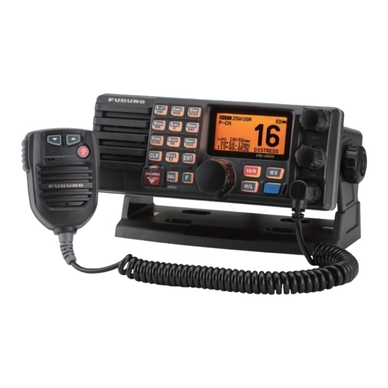
Page 16: Controls And Indicators
[ 16/9 ] key again to revert to the previously selected working chan- nel. Secondary use: Press the [ WX ] key while pressing and holding the [ 16/9 ] key to switch between USA, International and Canadian bands. Page 16 NOTE FM-4000... - Page 17 DISTRESS PULL OPEN Figure 4. Controls and Connectors FM-4000 Page 17...
- Page 18 Press the [ F ] key first then press the [ 3 ( SCAN )] key to start and stop the scanning of programmed channels. See section “10.13 SCANNING” for details. Page 18 [ 2 ( MEM )]) , deletes the channel from )] / FM-4000...
- Page 19 Press the [ F ] key first then press the [ 6 ( NAV )] key, and the LCD displays NAV GPS Data; Time, SOG (Speed Over Ground), and COG (Course Over Ground). Requires a GPS receiver, connected to the FM-4000 with the accessory cable. See section “8.5 ACCESSORY CABLE” for details.
- Page 20 Individual Ringer Group Directory Position Reply Position Input DSC Beep User MMSI : Shown when a GPS re- ceiver is not connected. Group Call Group Call Group Call Group Call,” Radio Setup” menu Radio Setup Radio Setup Radio Setup FM-4000...
- Page 21 ACCESSORY CONNECTION CABLE Connects the FM-4000 to a GPS receiver, a PA speaker, and an external speaker. DC INPUT CABLE Connects the radio to a DC power supply capable of delivering 12 to 16 V FRONT PANEL REMOTE MIC Connector Connects the supplied Hand Microphone if desired.
-
Page 22: Basic Operation
3. Press [ 0 ] until “A” appears to the right of the channel number. 4. Press [ ENT ]. 8. When a message is received, adjust the volume to the desired listening level. The “ ” indicator appears if the channel is busy. Page 22 FM-4000... -
Page 23: Transmission
[ WX ] key. “USA” appears for the USA mode, “INTL” for the International mode, and “CAN” for the Canadian mode. 2. See the VHF MARINE CHANNEL CHART (page 77) for allocated chan- nels in each mode. FM-4000 NOTE NOTE ”appears. Page 23... -
Page 24: Noaa Weather Channels
10.7.2 NOAA Weather Alert Testing NOAA tests the alert system every Wednesday between 11AM and 1PM. To test the FM-4000’s NOAA Weather feature at that time, setup as directed in section “10.7.1 NOAA Weather Alert” and confirm that you receive the alert. -
Page 25: Emergency (Ch16 Use)
For example, CH68 and CH69 of the U.S. VHF charts are some of the channels available to non-commercial (recreational) boaters. Monitor your de- sired channel in advance to make sure you will not be interrupting other traffic, FM-4000 ” (your vessel’s name). ” (your vessel’s name). -
Page 26: Making Telephone Calls
Call the marine operator and identify yourself by your vessel’s name. The marine operator will then ask you how you will pay for the call (telephone credit card, collect, etc.) and then link your radio transmission to the telephone lines. -
Page 27: Dual Watch (To Ch16)
2. If a transmission is received on the channel selected in step 2, the FM-4000 watches it and CH16. 4. To stop Dual Watch, press the [ F ] key followed by the [ 4 ( DW )] key again. -
Page 28: Priority Scanning (P-Scan)
6. To stop scanning, press the [ CLR ] , [ 16/9 ] , or [ WX ] key. You may change the scan resume time in the Radio Setup menu. See section “12.8 SCAN RESUME TIME.” Page 28 FM-4000... -
Page 29: Pa/Fog Operation
10.14 PA/FOG OPERATION The FM-4000 has a 30W Hailer that can be used with any 4 Ohm PA horn. When in the Hail mode, the PA speaker listens back (acts as a microphone and sends sound to the front panel speaker and the speaker MIC) through the PA horn speaker which provides two-way communications through the PA horn speaker. -
Page 30: Operating The Fog Horn Mode
1. Press the [ F ] key followed by the [ 1 ( DIM )] key to enable adjustment of the backlight intensity. 2. Turn the CHANNEL selector knob to select the de- sired backlight intensity. 3. Press the [ CLR ] key to return to “Radio” mode. Page 30 FM-4000... - Page 31 One 5-second blast followed by three 1- second blasts (separated by 2 seconds) every 120 seconds. AGROUND One 11-second ring every 60 seconds. ANCHOR One 5-second ring every 60 seconds. FM-4000 IMING Listen Back 120s Listen Back 120s Listen Back...
-
Page 32: Intercom Operation
1. Press and hold the [ 5 ( IC )] key while in the “Radio” mode to change to the “Intercom” mode. 2. If your FM-4000 is equipped two Remote MICs, use the CHANNEL selec- tor knob select the one of use (RAM1 ALL), then press the [ ENT ] key. -
Page 33: Calling
Hold down the [ 5 ( IC )] key when the “Intercom” mode is activated to send a calling beep to the Remote MIC. When both Remote MICs are set to the Intercom mode, the FM-4000 is temporarily disabled until both Remote MICs exit the Intercom mode. 10.18 VOICE SCRAMBLER If privacy of communications is desired, an optional CVS2500 four-code voice scrambler (VS) can be installed in the transceiver. -
Page 34: Digital Selective Calling
11.2 MARITIME MOBILE SERVICE IDENTITY ( MMSI ) 11.2.1 What is an MMSI? An MMSI is a nine-digit number used on marine transceivers capable of using DSC. This number is used like a telephone number to selectively call other ves- sels. Page 34... -
Page 35: Programming The Mmsi
9. Press the [ CLR ] key twice to return to the “Radio Setup” menu, then press the [ CLR ] key again Setup Setup Setup Setup to return to radio operation. FM-4000 WARNING User MMSI User MMSI.” User MMSI User MMSI Radio... -
Page 36: Dsc Distress Call
11.3 DSC DISTRESS CALL The FM-4000 is capable of transmitting and receiving DSC distress messages to all DSC radios. The FM-4000 may be connected to a GPS receiver to also transmit the latitude and longitude of your vessel. 11.3.1 Transmitting a DSC Distress Call To transmit a DSC Distress call, an MMSI number must be programmed. - Page 37 Transmitting a DSC Distress Alert with Nature of Distress The FM-4000 is capable of transmitting a DSC Distress Alert with the following “Nature of Distress” categories: Undesignated, Fire, Flooding, Collision, Grounding, Capsizing, Sinking, Adrift, Abandoning, Piracy, MOB 1. Lift the red spring-loaded DISTRESS key, then the [DISTRESS] key to show the “DISTRESS ALERT...
-
Page 38: Receiving A Dsc Distress Call
Cancel a DSC Distress Call If a DSC Distress call was sent by error, the FM-4000 allows you to send a message to other vessels to cancel the Distress call. Press the [ CLR ] key, then press the [ ENT ] key. -
Page 39: Transmitting An All Ships Call
11.5.1 Setting up the Individual / Position Call Directory The FM-4000 has a DSC directory that allows you to store a vessel or person’s name and the MMSI number associated with vessels you wish to transmit Individual calls, position requests and position send transmissions. - Page 40 To transmit an Individual call you must program this directory with information of the persons you wish to call, similar to the telephone directory of a cellular phone. 1. Press and hold down the [ CALL ( MENU )] key until the “Radio Setup...
-
Page 41: Setting Up Individual Reply
6. Press the [ ENT ] key to store the selected setting. 7. Press the [ CLR ] key twice to return to the “Radio Setup the [ CLR ] key again to return to radio operation. FM-4000 Individual Reply Individual Reply.”... -
Page 42: Transmitting An Individual Call
[ ENT ] key. 6. Press the [ ENT ] key again to transmit the individual DSC signal. Page 42 DSC Beep DSC Beep DSC Beep DSC Beep.” Off.” Radio Radio Radio Radio On” in step “6” in this FM-4000... - Page 43 5 is auto- matically selected and a ringing tone sounds. 12. Press the [ CLR ] key to listen to the channel to make sure it is not busy, then key the micro- phone to call the other vessel. FM-4000 Page 43...
-
Page 44: Receiving An Individual Call
7. Press the [ CLR ] key twice to return to the “Radio Setup the [ CLR ] key again to return to radio operation. Page 44 ” icon appears on the LCD. The FM-4000 can memo- Individual Ack Individual Ack Individual Ack.”... -
Page 45: Reviewing Received Calls Logged Into The Call Waiting Directory
6. Press and hold the [ ENT ] key until the station (name or MMSI number) is removed from the display. 7. To exit this menu and return to radio operation mode, press the [ 16/9 ] key. FM-4000 Distress Distress Distress Distress... -
Page 46: Group Call
Ship MMSI numbers. The first digit of a Group MMSI is always set to “0” in accordance with international regulations. All FURUNO radios are preset so when program- ming a Group MMSI the first digit is set to “0”. -
Page 47: Transmitting A Group Call
“Group” you want to contact. 5. Press the [ ENT ] key, then turn the CHANNEL selector knob to select the operating channel you FM-4000 A A A A A B B B B B C C C C C... - Page 48 9. Turn the CHANNEL selector knob to select the op- erating channel you want to communicate on, then press the [ ENT ] key. 10. Press the [ ENT ] key again to transmit the Group call signal. Page 48 FM-4000...
-
Page 49: Receiving A Group Call
11.7.3 Receiving a Group Call 1. When a Group call is received, the FM-4000 sounds a ringing alarm and the radio automatically switches to the requested channel. 2. Press any key to stop the alarm. -
Page 50: Position Request
Advancements in DSC have made it possible to poll the location of another vessel and show the position of that vessel on the display of the FM-4000. FURUNO has taken this feature one step further. If any FURUNO GPS chart... -
Page 51: Transmitting A Position Request To Another Vessel
GPS chart plot- ter. If the FM-4000 does not receive position data from the polled vessel, the LCD shows “NO POSITION DATA.” Manual Request You may enter an MMSI number manually to request the position of a vessel that is not registered in the Setting up the Individual / Position Call Directory. - Page 52 8. Press the [ ENT ] key to transmit the Position Request DSC call. 9. When the FM-4000 receives the position from the polled vessel it is shown on the radio dis- play and also transferred to the GPS chart plot- ter.
-
Page 53: Receiving A Position Request
/ Position Call Directory.” 11.9.1 Setting up a Position Send Ringer The FM-4000 has the capability to turn off the Position Send ringer as follows. 1. Press and hold down the [ CALL ( MENU )] key until the “Radio Setup Radio Setup”... - Page 54 7. When you have finished entering the MMSI num- ber, press and hold the [ ENT ] key. 8. Press the [ ENT ] key to send your position to the selected vessel. Page 54 FM-4000...
-
Page 55: Receiving A Dsc Position Send Call
11.9.3 Receiving a DSC Position Send Call When another vessel transmits its location to the FM-4000, the following oc- curs: 1. A ringing sound is generated when the call is received. 2. Press any key to stop the ringing sound. -
Page 56: Radio Setup
The contrast level can be set from “0 0 0 0 0 ” to “31 31.” 5. Press the [ ENT ] key to store the selected level. 6. To exit this menu and return to radio operation mode, press the [ 16/9 ] key. Page 56 NOTE Contrast FM-4000... -
Page 57: Time Offset
GMT Greenwich Mean Time). 5. Press the [ ENT ] key to store the time offset. 6. To exit this menu and return to radio operation mode, press the [ 16/9 ] key. FM-4000 Time Offset.” Time Offset 0:00” is assigned, the time... -
Page 58: Time Display
5. Press the [ ENT ] key to store the selected setting. 6. To exit this menu and return to radio operation mode, press the [ 16/9 ] key. Page 58 SOG Unit UTC” or ( “LOCAL” mode ) FM-4000... -
Page 59: True Magnetic Change (Nav Display)
5. Press the [ ENT ] key to store the selected setting. 6. To exit this menu and return to radio operation mode, press the [ 16/9 ] key. FM-4000 Magnetic Priority CH Mag- Mag-... -
Page 60: Scan Type
6. To exit this menu and return to radio operation mode, press the [ 16/9 ] key. 12.8 SCAN RESUME TIME Set the amount of time the FM-4000 waits after a transmission ends before starting scanning. 1. Press and hold down the [ CALL ( MENU )] key until the “Radio Setup... -
Page 61: Key Beep
Off.” 5. Press the [ ENT ] key to store the selected setting. 6. To exit this menu and return to radio operation mode, press the [ 16/9 ] key. FM-4000 Key Beep Key Beep.” Level 1” to Level 1... -
Page 62: Channel Naming
10. To exit this menu and return to radio operation mode, press the [ 16/9 ] key. Page 62 CH Name. CH Name 2 2 2 2 2 ... H H H H H I I I I I g g g g g h h h h h i i i i i FM-4000... -
Page 63: Naming The Radio Or Remote Mic
Name 9. If you want to enter the name of another unit, repeat steps 4 through 8. 10. To exit this menu and return to radio operation mode, press the [ 16/9 ] key. FM-4000 Unit Name Unit Name.” A A A A A... -
Page 64: Adjusting The Treble And Bass
5. Press the [ ENT ] key to store the selected setting. 6. To exit this menu and return to radio operation mode, press the [ 16/9 ] key. Page 64 Tone Control Tone Control Tone Control Tone Control.” Bass” with the Bass Bass Bass +6.” FM-4000... -
Page 65: Calendar Setup
The FM-4000 has a clock that remembers date, time, latitude and longitude. Connecting a GPS receiver to the FM-4000 is very important as it not only will be used to update the calendar automatically and also when a DSC Distress call is transmitted will send your vessel’s location to other vessels to aid in the... - Page 66 [UTC] mm [UTC] mm [UTC] Los Angeles 4:00PM (local) or 16:00 (24hour) 16:00 + 08:00 = 22:00 4:00PM (local) or 16:00 (24hour) 16:00 + 05:00 = 21:00 Rome 4:00PM (local) or 16:00 (24hour) 16:00 - 01:00 = 15:00 FM-4000...
- Page 67 Manual Manual Manual Manual.” 14. Press the [ ENT ] key to store the selected setting. 15. To exit this menu and return to radio operation mode, press the [ 16/9 ] key. FM-4000 Automatic Automatic Automatic Automatic” Page 67...
-
Page 68: Remote Mic Operation
13 REMOTE MIC OPERATION When the Remote MIC is connected to the FM-4000, most VHF, DSC, setup menus and PA modes can be remotely operated. The Remote MIC is supplied with 23 feet (7 m) of routing cable and can be extended up to 70 feet (21 m) using three 23-foot extension cables model CT-100. - Page 69 [ VOL/SQ ] Key (Volume Control / Squelch Control) Press this key to toggle the function of the Remote MIC’s [ ] or [ ] key between the channel selections, volume level adjustment, and squelch level adjustment. FM-4000 Page 69...
-
Page 70: Intercom Operation
1. Press one of the Soft key briefly to appear the key functions at the LCD bottom, then press the [ IC ] key to activate the “Intercom” mode. 2. If your FM-4000 is equipped with two Remote MICs, use the [ ] / [ ] key to select the station (RADIO... -
Page 71: Calling
(3 3 3 3 3 , 4 4 4 4 4 , or 6 6 6 6 6 ) and press the [ ENT ] key. 6. To exit this menu and return to radio operation mode, press the [ 16/9 ] key. FM-4000 Number of Number of Number of... -
Page 72: Define The Soft Keys
Page 72 Define [ [ [ [ [ SOFT SOFT ] ] ] ] ] Keys Define Define SOFT SOFT Keys Keys” Keys Define SOFT Keys FUNCTION ] key to select “Pr Pr Pr Pr Pr” (External Po” (External Speaker FM-4000... -
Page 73: Dsc/Radio Setup Mode
Individual Reply Individual Ack Individual Ringer Group Directory Position Reply Position Input DSC BEEP FM-4000 Radio Setup” or “DSC Radio Setup Radio Setup Radio Setup Function Sets the Individual Directory. Sets how to reply to an Individual call, Automatic or Manual. -
Page 74: Maintenance
Ensure that the supply voltage to the transceiver does not exceed 16 VDC or fall below 11 VDC. • Use only FURUNO-approved accessories and replacement parts. In the unlikely event of serious problems, please contact your dealer. Page 74 FM-4000... -
Page 75: Troubleshooting Chart
FM-4000 REMEDY a. Check the battery connections and the fuse. b. The PWR switch needs to be pressed and held to turn the radio on. -
Page 76: Channel Assignments
4. The S/D column on the chart indicates either S (simplex) or D (duplex). Sim- plex means transmitting and receiving on the same frequency. Only one party at a time can talk, unlike a telephone. Be sure to say “over” and release your microphone push-to-talk switch at the end of each transmission. Duplex op- eration involves the use of one frequency for transmitting and a separate fre- quency for receiving. - Page 77 D 157.250 161.850 Public Correspondence (Marine Operator) D 157.300 161.900 Public Correspondence (Marine Operator) D 157.350 161.950 Public Correspondence (Marine Operator) D 157.400 162.000 Public Correspondence (Marine Operator) FM-4000 VHF MARINE CHANNEL CHART CHANNEL USE 156.050 Port Operation and Commercial.
- Page 78 Canada: Commercial fishing only, International: Inter-ship, Port opertions and Ship movement 156.775 Port Operations (Inter-ship only) (1W) 156.825 Port Operations (Inter-ship only) (1W) 156.875 Port Operations (Inter-ship only) (1W) 156.875 Port Operations (Inter-ship only) Port operation, ship-movement 156.925 Non-commercial (Recreational) 156.975 Commercial FM-4000...
- Page 79 WX07 WX08 WX09 WX10 NOTE: Simplex channels, 3A, 21A, 23A, 61A, 64A, 81A, 82A and 83A CANNOT be lawfully used by the general public in U.S.A. waters. FM-4000 VHF MARINE CHANNEL CHART CHANNEL USE 157.025 Commercial 157.075 U.S. Government Only - Environmental protection operations.
- Page 80 G u a r d a n d a t Lake Mead, Nev., ship and coast stations of the N a t i o n a l P a r k S e r v i c e , U . S . Department of the Interior. FM-4000...
- Page 81 16: The frequency 156.450 MHz is available for intership, ship and coast general purpose calling by noncommercial vessels, such as recreational boats and private coast stations. 17: The frequency 156.425 MHz is assigned by rule to private coast stations in Alaska for facsimile transmissions as well as voice communications. FM-4000 Page 81...
-
Page 82: Specifications
(90 H x 230 W x 150 D mm) (72 H x 205 W x 130 D mm) pre-emphasis characteristic at 300 to 3000 Hz de-emphasis characteristic at 300 to 3000 Hz Input - GLL, GGA, RMC and GNS FM-4000... - Page 83 FM-4000 Page 83...
- Page 84 E M 0 2 8 N 1 5 0 Page 84 FM-4000...