Table of Contents
Advertisement
Advertisement
Table of Contents
Troubleshooting

Related Manuals for Furuno FR1500 Mk3


Summary of Contents for Furuno FR1500 Mk3
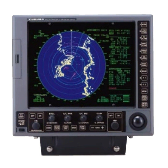
- Page 1 15" MULTI-COLOR HIGH-PERFORMANCE SHIPBORNE RADAR AND ARPA FR-1500 MARK-3 SERIES...
- Page 2 9-52 Ashihara-cho, 9-52 Ashihara-cho, Nishinomiya, Japan Nishinomiya, Japan Telephone : 0798-65-2111 Telephone : 0798-65-2111 Telefax : Telefax : 0798-65-4200 0798-65-4200 All rights reserved. All rights reserved. Printed in Japan Printed in Japan PUB.No. PUB.No. OME-34500 OME-34500 ( ( TATA TATA ) ) FR-1500 MARK-3 SER. FR-1500 MARK-3 SER.
- Page 3 SAFETY INSTRUCTIONS DANGER Before turning on the radar/ARPA, make sure that there is not one near the antenna unit. Serious injury or even death may result if a rotating antenna strikes someone standing nearby. WARNING Radio frequency Radiation Hazard The radar antenna emits electromagnetic radio frequency (RF) energy, which can be harmful, particularly to your eyes.
- Page 4 A warning label is attached to the equipment. Do not remove the label. If the label becomes soiled or illegible, contact a Furuno agent or dealer. No one navigation device should be solely relied on for navigation of a ship.
-
Page 5: Table Of Contents
TABLE OF CONTENTS INTRODUCTION ...v Specifications of FR-1500 Mark-3 Series shipborne radar...viii 1 OPERATIONAL OVERVIEW...1.1 1.1 Turning on the Power ...1 1.2 Transmitter ON...1 1.3 Control Description ...2 1.4 CRT Brilliance ...3 1.5 Control Panel Backlighting...3 1.6 Tuning the Receiver...3 1.7 Degaussing the Screen ...4 1.8 Initializing the Compass Readout ...4 1.9 Entering Own Ship’s Speed ...5... - Page 6 1.52 Real Time Heading Up (R-type only)...47 2 OPERATION OF AUTOMATIC TRACKING AID (ATA) ARP-17 ...2.1 2.1 Introduction ...1 2.2 Criteria of Tracking ...2 2.3 Activating, Deactivating the ATA...4 2.4 Entering Own Ship’s Speed ...5 2.5 Acquiring Targets ...6 2.6 Terminating Tracking of Targets ...8 2.7 Vectors True or Relative ...9 2.8 Displaying Target Data ...9 2.9 Past Position Display...10...
-
Page 7: Introduction
INTRODUCTION Word to the Owner of FURUNO Radar Thank you for purchasing this FURUNO radar. We are confident you will discover why FURUNO has become synonymous with quality and reliability. Dedicated in the design and manufacture of marine electronics equipment for half a century, FURUNO Electric Company has gained an unrivaled reputation as a world leader in the industry. - Page 8 Models This series of radar and ARPA is available in the following models: FR-1505 MARK-3 X-band 6 kW FR-1510 MARK-3 X-band 12 kW FR-1525 MARK-3 X-band 25 kW All come with the EPA (Electronic Plotting Aid) fitted standard. An option is available to provide the full functionality of ATA (Automatic Tracking Aid).
- Page 9 When the gyrocompass or magnetic compass is not connected to IMO type radar, the functions mentioned below are inoperative. In this case, the HDG SNSR on the SET UP 2 menu of the Installation menu should be set to OFF. (See page 5-7 in the installation manual.) 1.
-
Page 10: Specifications Of Fr-1500 Mark-3 Series Shipborne Radar
Specifications of FR-1500 Mark-3 Series shipborne radar ANTENNA RADIATORS 1. Type: Slotted waveguide array 2. Beamwidth: Radiator type: XN12AF XN20AF XN24AF Length: 4 ft 6.5 ft Beamwidth(H): 1.8° 1.23° Beamwidth(V): 20° 20° Sidelobe ±10°: -28 dB (all radiators) Polarization: Horizontal (all radiators) 3. -
Page 11: Equipment List
ENVIRONMENTAL CONDITIONS 1. Ambient temperature (Complies with IEC 60945) Display unit: -15 to +55 C Antenna unit: -25 to +70 C (Storage) 2. Relative humidity: 93% at 40 C EQUIPMENT LIST Standard .1 Display unit RDP-119 (AC or DC) .2 Scanner unit RSB-0074 (24 rpm), -0075 (42 rpm) with RF transceiver unit RTR-067 (6 kW), -062 (12 kW), -063 (25 kW) .3 Antenna radiator... - Page 12 CONFIGURATION OF FR-1500 MARK-3 SERIES RADARS FR-1505 MARK-3 FR-1510 MARK-3 FR-1525 MARK-3 ANTENNA UNIT RW-4873 (25C + 3C2V) DISPLAY UNIT RDP-119 ATA BOARD ARP-17, ARP-10 Gyro Interface PM INTERFACE VIDEO PLOTTER RECTIFIER 24 VDC RU-1746B-2 RU-3424 RU-3424 is for 42 rpm 25 kW antenna unit 115/230 VAC, 1ø, 50/60 Hz RADIATOR...
-
Page 13: Operational Overview
1 OPERATIONAL OVERVIEW 1.1 Turning on the Power The [POWER] switch is located at the left corner of the display unit. Push it to switch on the radar set. To turn off the radar, push it again. The screen shows the bearing scale and digital timer approximately 15 seconds after power-on. -
Page 14: Control Description
1.3 Control Description MENU ACCESS CONTROL PANEL Function keys are also used as numeral keypads for 0-9. POWER switch DIRECT ACCESS CONTROL PANEL BRILL STBY DAY/NIGHT (PUSH) DIMMER DEGAUSS (PUSH) TLL: Target Latitude/Longitude outputted in IEC 61162-1 format. Press to select presentation mode - Head-up (RM), Head-up True Bearing (RM), Course-up MODE (RM), North-up (RM), North-up (TM). -
Page 15: Crt Brilliance
1.4 CRT Brilliance Operate the BRILL control on the control panel of the display unit to adjust the entire screen brightness. Note that the optimum point of adjustment varies with ambient lighting conditions, especially between daytime and nighttime. 1.5 Control Panel Backlighting Operate the [DIMMER] key to adjust control panel backlighting. -
Page 16: Degaussing The Screen
1.7 Degaussing the Screen Each time the radar is turned on, the degaussing circuit automatically demagnetizes the CRT screen to eliminate color contamination caused by earth’s magnetism or magnetized ship structure. The screen is also degaussed automatically at certain time intervals, which may be selected on the menu. -
Page 17: Entering Own Ship's Speed
1.9 Entering Own Ship’s Speed EPA requires an own ship speed input and compass signal. The speed can be entered from a speed log (automatic) or through the plotting keypad (manual). 1.9.1 Automatic speed input 1. Press the [MENU] key and the [0] key twice to show the OTHERS menu. OTHERS 1. -
Page 18: On-Screen Legends And Markers
1.10 On-screen Legends and Markers Range scale Range ring interval Pulselength HU/HU TB/CU/NU/TM Heading line Heading marker 2nd Echo SART PULSE 1 M1 H U RM FUNC1 COAST EAV0.5 A/C AUTO CONTRAST1 287.2 R 50 R 240.0 R Stern marker Parallel index line reference 50 R EBL. -
Page 19: Presentation Modes
1.11 Presentation Modes This radar has the following presentation modes: Head-up, Head-up/TB, Course-up, North-up, and True Motion. 1.11.1 Selecting presentation mode Press the [MODE] key on the panel at the right side of the display unit. Each time the [MODE] key is pressed, the presentation mode and mode indication at the upper-left corner of the screen change cyclically. -
Page 22: Selecting The Range Scale
1.12 Selecting the Range Scale The display range scale is changed by pressing the [+] and [-] keys. The selected range scale and range ring interval are shown at the upper left corner on the screen. When a target of interest comes closer, reduce the range scale so that it appears in 50-90% of the display radius. -
Page 23: Adjusting The Sensitivity
1.14 Adjusting the Sensitivity The GAIN control adjusts the sensitivity of the receiver. It works in precisely the same manner as the volume control of a broadcast receiver, amplifying the signals received. The proper setting is such that the background noise is just visible on the screen. If you set up for too little sensitivity, weak echoes may be missed. -
Page 24: Suppressing Precipitation Clutter
1.16 Suppressing Precipitation Clutter The vertical beamwidth of the scanner is designed to see surface targets even when the ship is rolling. However, by this design the unit will also detect rain clutter (rain, snow, or hail) in the same manner as normal targets. Figure at right shows the appearance of rain clutter on the display. -
Page 25: Measuring The Range
1.18 Measuring the Range Use the fixed range rings to obtain a rough estimate of the range to a target. They are the concentric solid circles about own ship, or the sweep origin. The number of rings is automatically determined by the selected range scale and their interval is displayed at the upper-left position of the screen. -
Page 26: Measuring Bearing
1.19 Measuring Bearing Use the Electronic Bearing Lines (EBLs) to find bearing of a target. There are two EBLs, No.1 and No.2, which are toggled by successive presses of the [EBL ON] key. Each EBL is a straight dashed line extending out from the own ship position up to the circumference of the radar picture. The fine dashed line is the No.1 EBL and the coarse dashed one is the No.2 EBL. - Page 27 If relative motion is selected, it is also possible to read CPA (Closest Point of Approach) by using a VRM as shown below (Figure (a)). If the EBL passes through the sweep origin (own ship) as illustrated (Figure (b)), the target ship is on a collision course. 5.
-
Page 28: Measuring Range And Bearing Between Two Targets
1.21 Measuring Range and Bearing Between Two Targets 1. Press the [EBL OFFSET] key, and place the origin of the No.1 EBL on a target of interest (target 1 in the illustrated example) by operating the trackball. Note: Only No. 1 EBL can be offset. -
Page 29: Setting A Target Alarm Zone
1.22 Setting a Target Alarm Zone CAUTION The target alarm feature should never be relied upon as the sole means for detecting the risk of potential collision. The operator of a ship is not relieved of the responsibility to keep lookout for avoiding collisions, whether or not the radar is in use. -
Page 30: Off-Centering (Shift)
Note: To create a target alarm zone having a 360-degree coverage around own ship, set point B in almost the same direction (approx. ±3°) as point A and press the [TGT ALARM] key. Two alarm zones can be set as described above. To change the active alarm zones, do steps 1 through 4 in the above procedure. -
Page 31: Echo Averaging
CURSOR (a) Select location with cursor Note: The display is automatically reset to 75% of the range in use whenever the cursor is placed at an edge of the effective display area. Note also that the heading marker (small circle on the bearing scale) leaves the heading line on off-centered display, always indicating the correct direction of the own ship heading. - Page 32 Echo average is inoperable when a compass signal is not available. If you wish to use this feature without a compass signal, consult a FURUNO representative. Do not use the Echo Average function under heavy pitching and rolling; loss of target detection can result.
-
Page 33: Electronic Plotting Aid (Epa)
1.25 Electronic Plotting Aid (EPA) 10 targets can be plotted electronically to assess their motion trend. Five past positions can be displayed for each target. Working range of EPA is 0-48 nm irrespective of range scale. Note that EPA is disabled when the ATA (ARP-17) is accommodated. 000 010 020 340 350 Target data is shown in the data display area including range, bearing, course, speed, CPA and... - Page 34 Note: If a target once plotted is not plotted again within 10 minutes, the warning “UPDATE PLOT” and plot number will appear on the lower right margin of the screen and the plot symbol of the target flashes. Plotting of a target will be ceased if the time between consecutive plots exceeds 10 minutes. If you want to continue plotting this target, reacquire it within 5 minutes.
- Page 35 1.25.5 Terminating target plotting With EPA you can plot up to 10 targets. You may wish to terminate plotting of less important targets to newly plot other threatening targets. With Trackball: Place the cursor (+) on a target which you do not want to be tracked any longer by operating the trackball and press the [CANCEL/CLEAR] key.
-
Page 36: Target Trails (Echo Trails)
1.25.7 Silencing CPA/TCPA audible alarm Press the [AUDIO OFF] key to acknowledge and silence the CPA/TCPA audible alarm. The warning label COLLISION and the flashing of the triangle plot symbol and vector remain on the screen until the dangerous situation is gone or you intentionally terminate tracking of the target by using the trackball. - Page 37 TGT TRAIL 1. TIME (min) 15sec 30sec 1 3 6 30 CONT 2. MODE REL TRUE 3. SHADE MONO 4. LEVEL 1 2 3 5. TRAIL COPY OFF ON 6. THIN TRAIL OFF ON 7. THIN MODE 1 2 3 4 3.
- Page 38 1.26.5 Restoring trails Trails are cancelled and restarted whenever the range is changed. However, you can continue trails on the same range, without restarting, when the range is changed to a next larger or smaller range scale. Note however that when the range is changed, only those target trails within the previous range are continued;...
-
Page 39: Parallel Index Lines
1.27 Parallel Index Lines Parallel index lines are useful for keeping a constant distance between own ship and a coastline or a partner ship when navigating. The orientation of the index lines is controlled with the EBL rotary control and the intervals between the lines is adjustable with the VRM rotary control (provided that No.2 VRM is active). -
Page 41: Markers
1.30 Markers Heading line, north marker, stern marker, own ship symbol The heading line indicates the ship’s heading in all presentation modes. It is a line from the own ship position to the outer edge of the radar display area and appears at zero degrees on the bearing scale in head-up mode, it changes the orientation depending on the ship orientation in the north-up and true motion modes. -
Page 42: Suppressing Second-Trace Echoes
1.31 Suppressing Second-trace Echoes In certain situations, echoes from very distant targets may appear as false echoes (second-trace echoes) on the screen. This occurs when the return echo is received one transmission cycle later, that is, after a next radar pulse has been transmitted. To activate or deactivate the second-trace echo rejector: 1. -
Page 43: F2] Key
1.33 [F2] Key The [F2] key selects the level or setting for one of the parameters as selected at step 3 below on the STBY screen. 1.33.1 Presetting the [F2] key 1. In the STANDBY condition, press the [MENU] key. 2. -
Page 44: Function Key
1.34 FUNCTION Key The FUNCTION key works similar to the automatic dialing feature on a telephone, playing back control settings just as they were registered. Instead of manually adjusting controls to set up for a particular condition, for example, navigation in a harbor, you can have the [FUNCTION] key to do it for you. - Page 45 1.34.2 Activating/deactivating a function Press the [FUNCTION] key. Each time the key is pressed a preset function the preset functions enabled on the FUNC menu are turned on or off cyclically. You may enable/disable preset functions from the menu as follows: 1.
-
Page 46: Adjusting Brilliance Of Screen Data
1.35 Adjusting Brilliance of Screen Data You can adjust relative brilliance levels of various marks and alphanumeric readouts displayed on the screen as follows: 1. Press the [MENU] key. 2. Press the [9] key twice to show the BRILL menu. 3. -
Page 47: Echo Stretch, Contrast, Enhanced Video
1.36 Echo Stretch, Contrast, Enhanced Video On long ranges target echoes tend to shrink in the bearing direction, making them difficult to see. On short and medium ranges such as 1.5, 3 and 6 nm scales, the same size targets get smaller on screen as they approach the own ship. -
Page 48: Watch Timer
1.36.3 Enhanced video The enhanced video function works similar to the echo stretch function, enlarging target echoes in bearing and range direction on 1.5-6 nm scales. ECHO SIG 1. COLOR YEL GRN 2. CLTR SWEEP OFF ON (LINK) ON(FIX) 3. SWEEP LEVEL 1 2 3 4. -
Page 49: Noise Rejector
1.38 Noise Rejector The noise rejector suppresses white noise, which appears on the screen as many dots scattered randomly over the display. To suppress white noise: 1. Press the [F1] key. 2. Press the [7] key to turn the noise rejector on or off as appropriate. NR appears at lower left-hand position when the noise rejector is on. -
Page 50: Degaussing Interval
1.42 Degaussing Interval The screen is degaussed automatically at certain time intervals, as well as each time the radar is turned on, to eliminate color contamination caused by earth’s magnetism or magnetized ship structure. You can select the degaussing interval and the degaussing degree as follows: 1. -
Page 51: Day, Night Brilliance
3. Press the [2] key to turn on/off the clutter sweep function: OFF: Turns off clutter wiper feature. ON(LINK): Sweep area moves with trackball operation. Sweep cursor shown by dashed lines. ON(FIX): Sweep area is fixed on the screen. Sweep cursor shown by solid lines. 4. -
Page 52: Radar Map (Rp-17 Board Required)
1.47 Radar Map (RP-17 board required) A radar map is a combination of map lines and symbols whereby the user can define and input the navigation data, route planning and monitoring data. Map lines (also called nav lines) are navigational facility whereby the observer can define lines to indicate channels or traffic separation schemes. - Page 54 1.47.3 Position and bearing correction There may be some instances where the map latitude and longitude are out of radar pictures for several seconds. You can compensate this error as follows: 1. Press the [MENU] key. 2. Press the [8] key twice to display the MARK menu. 3.
- Page 55 Separation zone Target being tracked Dangerous side of own ship safe contour may be marked like this. 1.47.4 Displaying the radar map 1. Press the [MENU] key to display the Main menu. 2. Press the [8] key twice to display the MARK menu. 3.
-
Page 56: Alarms
1.48 Alarms The table below summarizes alarms which may occur at various warning conditions. Warning Audible alarm HEADING 2 beeps failure Target alarm Beeps (TAZ) WATCH alarm Beeps Own ship None lat/lon Cursor lat/lon System failure None Incorrect Double keystroke beep tone Log failure 2 beeps... - Page 57 Warning may not beep None on the SIGNAL MISSING cell. TRIG: no trigger signal from the scanner unit. AZIMUTH: no azimuth signal (turning signal). See SYSTEM FAILURE column. VIDEO: no video signal from the RF transceiver. GYRO: no gyrocompass signal due to disconnected lines(s).
-
Page 58: Enlarging Close-In Targets (R-Type Only)
1.49 Enlarging Close-in Targets (R-type only) All targets within the first range ring can be enlarged as follows: 1. Press the [MENU] key to open the menu. 2. Press the [5] key twice to display the ECHO SIG menu. ECHO SIG 1. -
Page 59: Echo Area (R-Type Only)
1.51 Echo Area (R-type only) You may select the size of the area in which echoes are displayed as follows: 1. Press [MENU], [0], [0], [5], [5] to show the DISPLAY menu. DISPLAY 2. NAV DATA OFF ON 3. ECHO AREA CIRCLE WIDE 2. -
Page 60: Operation Of Automatic Tracking Aid (Ata) Arp-17
2 OPERATION OF AUTOMATIC TRACKING AID (ATA) ARP-17 2.1 Introduction The FR-1500 MARK-3 series radar can accommodate an optional ATA (Automatic Tracking Aid) module complying with IMO MSC.64(67) Annex 4 and IEC 60872-2. With the optional ATA circuit board (ARP -17) fitted in the display unit, the radar will automatically acquire 10 targets coming into the acquisition area. -
Page 61: Criteria Of Tracking
Echoes smaller than 800 m are regarded as targets to be tracked. The FURUNO ARPA ATA video processor detects targets in the midst of noise and discriminates radar echoes on the basis of their size. Target whose echo measurements are greater than those of the largest ship in range or tangential extent are usually land and are displayed only as normal radar video. - Page 62 Automatic acquisition areas and suppression lines Performance of auto-acquisition is enhanced by controlling the limit lines (suppression lines) in the former series of FURUNO ARPAs. In the ATA, the automatic acquisition rings are used instead of the limit lines. Auto acquisition rings work as suppression lines when viewed from the opposite direction. They should be placed clear of a landmass or shoreline.
-
Page 63: Activating, Deactivating The Ata
2.3 Activating, Deactivating the ATA The ATA is activated/deactivated through the menu. Acquired targets are tracked internally when the ATA is deactivated. 1. Adjust the A/C RAIN, A/C SEA and GAIN controls for proper radar picture. 2. Press [MENU], [7] to show the PLOT MENU 1 PLOT MENU 1 1. -
Page 64: Entering Own Ship's Speed
2.4 Entering Own Ship’s Speed The ATA requires own ship’s speed and heading data. Of these, the speed data can be entered automatically from a speed log, navaid or manually through the menu. Note: It is customary to use a speed relative to water for collision avoidance and a speed over the ground for navigation purpose. -
Page 65: Acquiring Targets
2.4.2 Manual speed input Select MAN at step 2 in preceeding procedure, press the [3] key twice, and enter a speed with numeral keypads. Target-based speed input This mode is used when the ship’s SDME (log) is not operating properly or the vessel has no device which detects ship’s leeward movement (Doppler sonar 2-axis speed log, etc.) and leeward movement is not disregarded. - Page 66 The plot symbol changes its shape according to the status as below. A vector appears in about one minute after acquisition, indicating the target’s motion trend. If the target is consistently detected for three minutes, the plot symbol changes to a solid mark. If acquisition fails, the target symbol blinks and disappears shortly.
-
Page 67: Terminating Tracking Of Targets
2.5.3 Changing plot symbol mark The plot symbol for a target may be changed after acquiring the target. This feature is available on the R-type radar. 1. Place the cursor on the plot symbol mark you wish to change. 2. Press the [ENTER/SELECT] key successively while pressing and holding down the [HL OFF] control to select plot symbol mark desired. -
Page 68: Vectors True Or Relative
2.7 Vectors True or Relative Target vectors are displayed in relative or true mode. Own ship does not have a vector in relative mode. You may select true or relative vector with VECT REF on the PLOT MENU 1. 2.7.1 Vector time From the PLOT MENU 1, VECT TIME (or the length of vectors) can be set to 30 seconds, 1, 3, 6, 15 or 30 minutes and the selected vector time is indicated on the screen. -
Page 69: Past Position Display
2.9 Past Position Display The ATA displays equally time-spaced dots (maximum 10 dots at intervals of 30 seconds, 1, 2, 3 or 6 minutes) marking the past positions of any targets being tracked. If a target changes its speed, the spacing will be uneven. If it changes the course, its plotted course will not be a straight line in TM mode. -
Page 70: Alarms
2.11 Alarms 2.11.1 CPA/TCPA alarm Visual and audible alarms are generated when the predicted CPA and TCPA of any target become less than their preset limits. The ATA continuously monitors the predicted range at the Closest Point of Approach (CPA) and predicted time to CPA (TCPA) of each tracked target to own ship. - Page 71 2.11.3 Guard zone alarm When a target comes in a guard zone, the audible alarm comes on with the visual indication GUARD ZONE. The intruding target is denoted by an inverted triangle mark. If the target leaves the zone, it changes to a normal tracking symbol (O). You can set the guard zone as follows: 1.
-
Page 72: Track Test (Simulation Display)
2.12 Track Test (Simulation Display) Do this test when the radar is not being used. The simulation display tests the ATA processor for proper operation. The figure below shows the starting picture of the simulation display. Each mark moves as time passes. Check that each target’s data is reasonable. -
Page 73: Diagnostic Sequence
2.14 Diagnostic Sequence You can check the ATA Board for proper operation as follows. The self test does not require operator intervention. It runs automatically when the power is placed on at regular intervals or on operator demand. 1. Press [MENU], [0], [0], [0], [0]. 2. -
Page 74: Factors Affecting Arpa Functions
2.15 Factors Affecting ARPA Functions Sea returns If the radar anti-clutter control is adjusted properly, there is no serious effect because distant wave clutter, not eliminated by this control, is filtered out by more than one bang correlation and scan-to-scan matching of data. Rain and snow Clutter can be acquired and tracked as targets. - Page 75 Indirect echoes A target at close range is usually picked up directly, but it can also be received as reflection from a large, flat surface. This will result in the radar presenting two or more echoes on the display, each at a different range.
-
Page 76: Radar Observation
It is a good practice to use a shorter range scale as far as it gives favorable definition or clarity of picture. The IMO Resolution A. 477 (XII) and IEC 936 require the minimum range to be less than 50 m. All FURUNO radars satisfy this requirement. Maximum range... - Page 77 This is determined by pulselength only. Practically, a 0.08 microsecond pulse offers the discrimination better than 35 m as do so with all FURUNO radars. Test targets for determining the range and bearing resolution are radar reflectors having an echoing...
-
Page 78: False Echoes
3.2 False Echoes Occasionally echo signals appear on the screen at positions where there is no target or disappear even if there are targets. They are, however, recognized if you understand the reason why they are displayed. Typical false echoes are shown below. Multiple echoes Multiple echoes occur when a transmitted pulse returns from a solid object like a large ship, bridge, or breakwater. -
Page 79: Sart (Search And Rescue Transponder)
3.3 SART (Search and Rescue Transponder) A Search and Rescue Transponder (SART) is generally carried on the SOLAS Convention ships under the GMDSS scheme. It serves as a homing device for the rescue party to reach the survival craft in distress. It is triggered by any X-Band (3 cm) radar within a range of approximately 5 nm (IMO Resolution A.802 (19)). - Page 80 General remarks on receiving SART Radar range scale When looking for a SART it is preferable to use either the 6 or 12 nautical mile range scale. This is because the total displayed length of the SART response of 12 (or 24) dots may extend approximately 9.5 nautical miles beyond the position of the SART and it is necessary to see a number of response dots to distinguish the SART from other responses.
-
Page 81: Racon (Radar Beacon)
A/C RAIN control This should be used normally (i.e. to break up areas of rain) when trying to detect a SART response which, being a series of dots, is not affected by the action of the anti-clutter rain circuitry. Note that RACON responses, which are often in the form of a long flash, will be affected by the use of this control. -
Page 82: Operation Of Video Plotter Rp-17 (Option)
FR-1500 MARK-3 series radars. It permits use of two memory cards: a memory card(RAM) for storing the operator-created radar maps, and the other is a chart card(ROM) storing FURUNO made digital charts. The memory card enables the operator to create radar maps more precisely than the standard supplied radar map card. -
Page 83: Maintenance
5 MAINTENANCE WARNING Do not open the equipment Hazardous voltage which can cause electrical shock exists inside the equipment. Only qualified personnel should work inside the equipment. Turn off the radar power switch before servicing the antenna unit. Post a warning sign near the switch indicating it should not be turned on while the antenna unit is being serviced. -
Page 84: Life Expectancy Of Major Parts
High voltage at CRT and surrounding components attract dust in environment which will cause poor insulation. Ask your nearest FURUNO representative or dealer to clean internal high- voltage components. Check for loose connections. Check contacts and plugs for proper seating, etc. -
Page 85: Troubleshooting
TROUBLESHOOTING 6.1 Easy Troubleshooting This paragraph describes how to cure operational problems, which can be made by observing the radar picture and using operator controls and keys without opening the display unit, antenna unit or other equipment units. Problem Power turned on but radar does not operate at all. -
Page 86: Advanced-Level Troubleshooting
6.2 Advanced-level Troubleshooting This paragraph describes how to cure hardware and software troubles which should be carried out by qualified service personnel. Note: This radar equipment contains complex modules in which fault diagnosis and repair down to component level are not practicable by users. Serviceman qualification All adjustments of radio transmitter during or coinciding with the installation, servicing, or maintenance which may affect the proper operation must be performed by or under the immediate... - Page 87 Problem Antenna not rotating Data and marks not displayed in Transmit status Adjust GAIN control with A/C SEA control set at minimum. Marks and legends appear but no noise or echo. Marks, legends and noise appear but no echo: (Transmission leak representing own ship position is absent.) Picture not updated or picture freeze-up.
- Page 88 Problem TUNE control adjusted but poor sensitivity. Range changed but radar picture not changing. Interference rejector inoperable (interference rejection level not displayed) Echo stretch ineffective (Neither ES1 nor ES2 is displayed) Only 2 parallel index lines when 6 lines are wanted. Range rings are not displayed.
- Page 89 Problem Poor discrimination in range True motion presentation not working correctly Target nottracked correctly Probable causes or check Remedy points Sea clutter control not functioning properly Poor contact of MODE 1 Try to press MODE key a little harder. Selection not accessed 2 Press MODE key until TM appears.
-
Page 90: Diagnostic Test
6.3 Diagnostic Test A diagnostic test program is provided to enable testing of major circuit boards in the radar display unit. Note that the normal radar picture is lost during this test. Proceed as follows to execute the diagnostic test: 1. - Page 91 FR-1500 M-3 SERIES TEST 1. Program No. 2. ROM Check 3. RAM Check 4. Antenna Rotation 5. TX Trigger Frequency 6. Video Level 7. Video Signal ARP TEST 1. Program No. 2. ROM Check 3. RAM Check 4. Speed Log 5.
-
Page 92: Menu Hierarchy
6.4 Menu Hierarchy [MENU] key 1. VIDEO PLOT 2. TGT TRAIL 3. TGT ALARM 4. WATCH TIME 5. ECHO SIG 6. FUNC 7. PLOT 8. MARK 9. BRILL 0. OTHERS 1. TIME(Min) 2. MODE 3. SHADE 4. LEVEL 5. TRAIL COPY OFF ON 6. - Page 93 [MENU] key + [FUNC MENU] 1. FUNC1 OFF ON 2. FUNC2 OFF ON 3. FUNC3 OFF ON 4. FUNC1 SET 5. FUNC2 SET 6. FUNC3 SET 7. F.2 SET [4], [5], 2. FUNC SEL CST OCEAN R-SEA FLT BY HBR L RAIN 3.
- Page 94 [MENU] key + [BRILL MENU] 1. TGT TRAIL 2. CHARACTER 3. HDG LINE 4. EBL/VRM 5. CURSOR 6. MARK 7. PLOT 8. OS SYMB [OTHER MENU] 1. HDG SET (0.0-359.9˚) 2. SPD MODE MAN LOG NAV* LOG (S-BT) LOG (S-WT) 3.
-
Page 95: Optional Equipment
A performance monitor is required for a radar installed on certain type of ship as determined by the Administrations. The FURUNO PM-30 (for X-band radars) covers 9410 ± 50 MHz. It works on the transponder principle. It sends response back to the radar antenna upon receiving the pulse from the radar antenna and determines if transmitter or receiver or both are deteriorated in comparison with the state of the precious calibration. - Page 96 12 nm 4 arcs starting at 12 nm Transmitter: normal Receiver: normal 9 nm Transmitter: 3 dB loss (Transmitter system has lost a half of initial power. Suspect magnetron.) Receiver: normal -7.2- 9 nm Transmitter: 3 dB loss (Transmitter system has lost a half of initial power.
-
Page 97: Digital Interface (Iec 61162-1 Edition 1 And 2)
8 DIGITAL INTERFACE (IEC 61162-1 Edition 1 and 2) 1 I/O Sentences for Channel 1 Input BWC, BWR, DBK *, DBS *, DBT, DPT, GDD *, GGA, GLL, GTD *, HDG, HDM *, MDA *, MTW (*), RMA, RMB, RMC, VBW, VHB, VTG(*), ZDA (* ) not recommended in IMO type, * R-Type Only Output RSD (every 4 s), TLL * (When A/C RAIN control is pressed.) - Page 98 Position data GPS: GPGGA > GPRMC > GPGLL LCRMA > LCGLL Timeout: 30 seconds Time difference (TD) LCRMA > LCGLC > LCGTD * Date, time data GPZDA Timeout: 10 seconds Course heading, speed over ground In the case of log **VBV In the case of EPFS GPS:...
-
Page 99: Description Of Sentences
Description of Sentences Note: Checksum for RMA, RMB and RMC is mandatory. Checksum for other sentences is evaluated if it exists. BWC - Bearing and distance to waypoint BWR - Bearing and distance to waypoint - rhumb line Time (UTC) and distance and bearing to, and location of, a specified waypoint from present position. - Page 100 DBS - Depth below sea surface $--DBS,x,x,f,x,x,M,x,x,F*hh<CR><LF> Depth (meters) Depth (feet) * * Not used DBK - Depth below keel DBT - Depth below transducer Water depth referenced to the transducer. $--DBT, x.x, f, x.x, M, x.x, F*hh<CR><LF> Water depth, m Water depth, feet * * Not used DPT - Depth...
- Page 101 GGA - Global positioning system (GPS) fix data Time, position and fix related data for a GPS receiver. Differential reference station ID, 0000-1023 * Age of differential GPS data (see note 2) * Antenna altitude above/below Horizontal dilution of precision * $--GGA, hhmmss.ss.
- Page 102 HDG - Heading, deviation and variation IMO Resolution A.382 (X). Heading (magnetic sensor reading), which if corrected for deviation, will produce magnetic heading, which if offset by variation will provide true heading. $--HDG, x.x, x.x, a, x.x, a*hh<CR><LF> Magnetic variation, degrees, E/W (see notes 2 and 3) Magnetic deviation, degrees, E/W (see notes 1 and 3) Magnetic sensor heading, degrees * Not used...
- Page 103 RMA - Recommended minimum specific LORAN-C data Position, course and speed data provided by a LORAN-C receiver. Time differences A and B are those used in computing latitude/longitude. Checksum is mandatory in this sentence. This sentence is transmitted at intervals not exceeding 2 s and is always accompanied by RMB when a destination waypoint is active.
- Page 104 RMB - Recommended minimum navigation information Navigation data from present position to a destination waypoint provided by a LORAN-C, TRANSIT, OMEGA, GPS, DECCA, navigation computer or other integrated navigation system. Checksum is mandatory in this sentence. This sentence always accompanies RMA or RMC sentences when a destination is active when provided by a LORAN-C, TRANSIT or GPS receiver, other systems may transmit $--RMB without $--RMA or $--RMC.
- Page 105 RMC - Recommended specific GPS/TRANSIT data Time, date, position, course and speed data provided by a GPS or TRANSIT navigation receiver. Checksum is mandatory in this sentence. This sentence is transmitted at intervals not exceeding 2 s and is always accompanied by RMB when a destination waypoint is active. RMC and RMB are the recommended minimum data to be provided by a GPS or TRANSIT receiver.
- Page 106 TLL - Target latitude and longitude Target number, name, position and time tag for use in systems tracking targets. $--TLL, xx, 1111.11, a, yyyyy.yy, a, c--c, hhmmss.ss, a, a*hh<CR><LF> Latitude, N/S Target number 00 – 99 * * Not used NOTE - Target status: L = lost, tracked target has been lost Q = query, target in the process of acquisition...
- Page 107 VBW - Dual ground/water speed: This sentence to be expanded as shown below: $--VBW, x.x, x.x, A, x.x, x.x, A, x.x, A, x.x, A *hh<CR><LF> Status, water speed, A = data valid Transverse water speed Longitudinal water speed NOTES 1. Transverse speed: “-“ = port, Longitudinal speed: “-“astern. 2.
- Page 108 ZDA - Time and date UTC, day, month, year and local time zone. $--ZDA. hhmmss.ss, xx, xx, xxxx, xx, xx*hh<CR><LF> Checksum Local zone description, minutes * Local zone description, hours * Year Month, 01 to 12 Day, 0 to 31 Not used * LOCAL = UTC + Time difference -8.12-...
-
Page 109: Parts Location And Parts List
9 PARTS LOCATION and PARTS LIST 9.1 ANTENNA UNIT, SCANNER OUTLINE and RF MODULE Figure A-1 Display unit, right side view Figure A-2 Display unit, left side view -9.1-... - Page 110 RGB-BUFF Board (Option) 03P9229 Figure A-3 Display unit, top view ATA Board ARP-17 (Option) 18P904A Figure A-4 Display unit, rear view TB Board RF Module 03P9242 Figure A-5 Scanner unit -9.2- SPU Board 03P9230 S901 MP-3795 Board Motor (Bow View)
- Page 111 IF Board 03P9232 Figure A-6 RF module -9.3- MIC Assy. RU-9099 (For RTR-067) RU-9253 (For RTR-063) RU-9371 (For RTR-062) Diode Limiter RU-9099 RFC Board 03P9243...
- Page 112 MD Board 03P9244 J811 J812 Figure A-7 RF module, rear view -9.4- Fan Motor Assy. 03-1900 Pulse Transformaer RT-9025 (For RTR-062, RTR-067) RT-9023 (For RTR-063) Magnetron E3560, MG52389 (For RTR-067) MG5241 (For RTR-062) MG5436 (For RTR-063)
-
Page 113: Circuit Diagrams
9.2 Circuit diagrams FR-1500 Mark-3 SERIES SERIAL INTERFACE I/O CIRCUIT TALKER (60 mA max) LISTENER (2 mA at 2 V) CHANNEL 1 OUTPUT RSD, TLL CHANNEL 1 RD1-A INPUT RD1-B BWC, BWR, DBS, etc. J203 B5B-XH-A CHANNEL 2 RD2-A INPUT RD2-B DBK, DBS, DPT, MDA, MTW, VBW... - Page 114 FR-1500 MARK-3 series interfacing diagram CHANNEL 2 OUTPUT -9.6-...
- Page 115 -9.7-...
-
Page 116: Parts List
9.3 Parts list FR-1505/1515/1525 MARK-3 DISPLAY UNIT RDP-119 FR-2115/2125 ELECTRICAL PARTS LIST 98/5 SYMBOL TYPE PRINTED CIRCUIT BOARD HV9017A, HV HV9017B, HV 03P9230A, SPU 64P1106A, GC 03P9259C, RP-17 18P9004, ARP-17 18P9007, ARP-10 CRT ASSEMBLY 0A1510 PANEL ASSEMBLY RDP-119, PNL/SW POWER BLOCK ASSY RDP-119-6/10/25 KW RDP-119-6/10/25 KW RDP-119-6/10 KW... - Page 117 FR-1505/1515/1525 MARK-3 Model FR-2115/2125 ELECTRICAL PARTS LIST 98/5 SYMBOL TYPE PRINTED CIRCUIT BOARD 03P9243A, RFC 03P9243B, RFC 03P9244A, MD 03P9244B, MD 03P9232, IF 03P9242, TB MP-3795 SCANNER CHASSIS RSB-0074 RSB-0075 RF MODULE RTR-062 RTR-063 RTR-067 MIC ASSEMBLY U801 RU-9253 RU-9371 MOTOR B801 D8G-516...
- Page 118 SYMBOL TYPE CIRCULATOR HY801 RC-3686 RESISTOR R899 ERF-10HMJ102 TRANSFORMER T801 RT-9025 RT-9023 MAGNETRON V801 M5436 E3566 MG5241 E3560 CODE No. REMARKS 000-106-850 000-123-395 000-123-823 6, 10, 12 KW 000-123-394 F25 KW 000-140-762 25 KW 000-141-073 10 KW 000-100-036 12 KW 000-139-050 6 KW -9.10-...