Advertisement
Quick Links
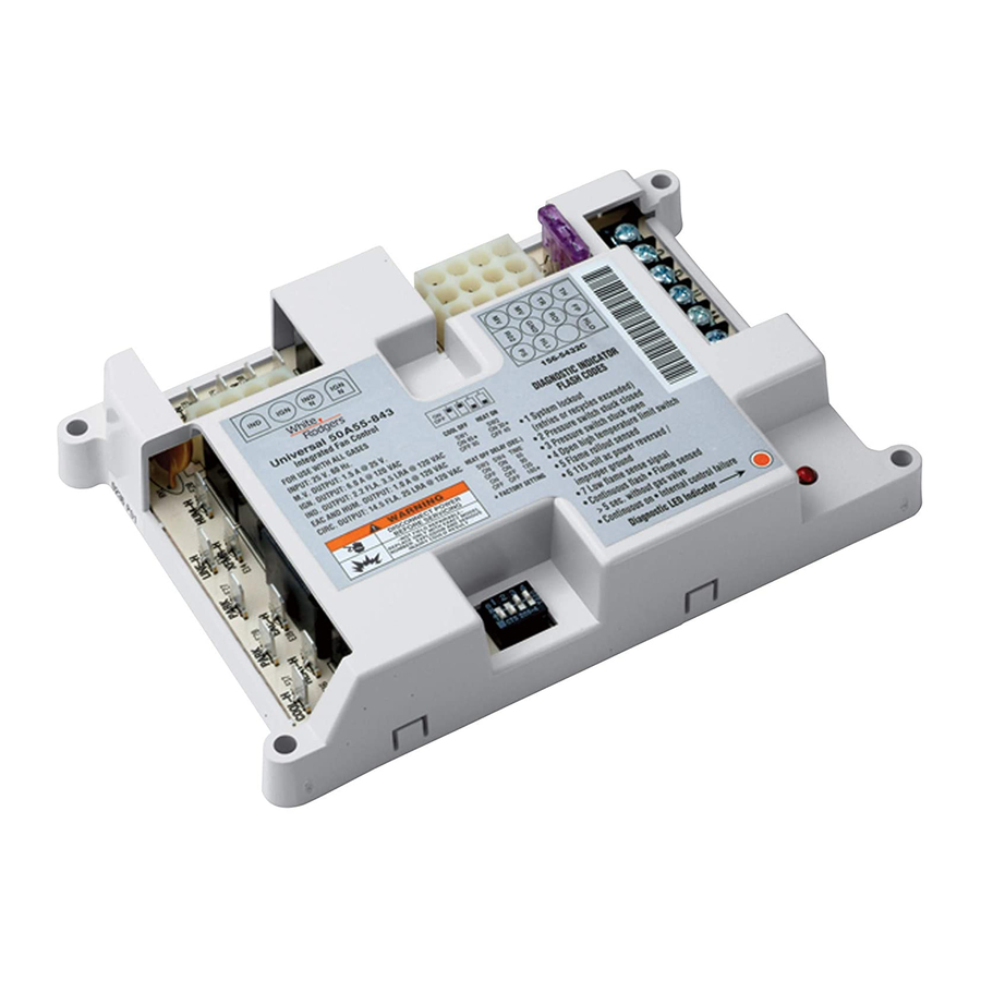
INTEGRATED FURNACE
CONTROL MODULE
WARNING
!
Failure to read and follow all
instructions carefully before in-
stalling or operating this control,
could cause personal injury and/
or property damage.
FAULT INDEX CHART
No manual fan ............................................ 1A - 1K
Power supply and voltage .......................... 1C - 1G
No fan at cooling speed .............................. 2A - 2L
No induced draft motor ............................... 3A - 3H
LED flashing 2X without inducer................. 3E
LED flashing 3X with inducer...................... 3I - 3O
Ignitor does not glow .................................. 4A - 4D
Burner does not stay lit ............................... 4E - 4N
Gas supply problem.................................... 4F - 4K
No outlet pressure ...................................... 4H - 4J
Gas valve does not energize ...................... 4L - 4N
Flame sensor fault ...................................... 5A - 5P
Burner ground............................................. 5K
Polarity check ............................................. 5L - 5M
Ignitor stays on after burner ignition ........... 5B - 5C
50A55 INTEGRATED FURNACE CONTROL MODULE
Qualified Serviceman's Troubleshooting Guide
TROUBLESHOOTING PROCEDURE
If the light on the module is on continuously, the fault is likely to be internal to the
module. To make sure, interrupt line or 24 volt thermostat power for a few seconds
and then restore. If internal fault is indicated again, and flame sensor is not shorted
to ground, replace control. A flashing light indicates the problem is most likely in the
external components or wiring. Proceed as follows:
WARNING
!
Turn power off before any troubleshooting or servicing begins.
Line voltage (120 VAC) could be present on the surface of the ignitor, if the sys-
tem is not correctly wired. Such voltage can cause serious injury or death.
The following steps must be performed first before any troubleshooting begins.
1) Disconnect electric power to system at main fuse or circuit breaker.
2) Visually inspect equipment for apparent damage. Check wiring for loose
connections.
3) Check for proper grounding and reversed polarity.
A. Check continuity for C terminal on module to electrical service ground and
connection at the furnace junction box. If ground connection is open, check
module ground connection and the electrical service ground connection.
Repair and retest.
B. Re-connect electric power to system.
C. Check for voltage between the line neutral terminal and furnace ground. If
voltage exists, the main power supply lines are improperly connected to the
furnace (REVERSED POLARITY). Again disconnect electric power to system;
then reverse incoming supply leads to furnace. Repeat step.
D. Recheck system for proper operation.
If neither apparent damage, loose connection nor reversed polarity is the problem,
proceed to troubleshooting chart or fault index chart that is suggested by the actual
condition.
NOTE: This troubleshooting guide is not for 50A55-4XX modules found on Trane
equipment or 50A55-1XX modules found on Lennox equipment.
www.white-rodgers.com
TROUBLESHOOTING
GUIDE
189
Advertisement

Related Manuals for White Rodgers 50A55


Summary of Contents for White Rodgers 50A55
-
Page 1: Troubleshooting Guide
If neither apparent damage, loose connection nor reversed polarity is the problem, proceed to troubleshooting chart or fault index chart that is suggested by the actual condition. NOTE: This troubleshooting guide is not for 50A55-4XX modules found on Trane equipment or 50A55-1XX modules found on Lennox equipment. FAULT INDEX CHART No manual fan .......... - Page 2 TROUBLESHOOTING INTEGRATED FURNACE GUIDE CONTROL MODULE CHART 1 Place Return fan thermostat Does indoor Indoor Blower switch to fan switch in blower run at Check AUTO position. the ON HEAT speed? position. Is 120V Does LED Is 24V Is 24V Indoor blower present at flash 1 time...
-
Page 3: Troubleshooting
INTEGRATED FURNACE TROUBLESHOOTING CONTROL MODULE GUIDE CHART 2 Place thermostat system switch in cooling mode and fan Does indoor Cooling Return thermostat switch in AUTO blower energize Cycle to desired position. Lower at cooling setting. Check temperature selection fan speed? lever to call for a cooling cycle. - Page 4 TROUBLESHOOTING INTEGRATED FURNACE GUIDE CONTROL MODULE CHART 3 Call for heat. Inducer Draft Motor Is induced Is diagnostic Thermostat draft motor LED flashing 3 Pressure Switch contacts energized? times? Check R & W close. Is diagnostic Jumper LED flashing 2 pressure times? switch.
- Page 5 INTEGRATED FURNACE TROUBLESHOOTING CONTROL MODULE GUIDE CHART 4 Does ignitor Main Burner Does burner warm up and Ignition Check. ignite? glow? Inducer ON. Turn power OFF to furnace. Unplug ignitor from wire Is gas harness. Connect voltmeter Turn manual knob valve manual across ignitor wiring to ON position.
- Page 6 TROUBLESHOOTING INTEGRATED FURNACE GUIDE CONTROL MODULE CHART 5 Is blower System is Does main at heat speed Flame Does ignitor remain functioning burner remain within 1 minute Sensor energized with properly. lit? of burner ignition? Check flame present? De-energize system. Disconnect 12-pin Is 120V Repair wiring...