Table of Contents
Advertisement
Quick Links
Operator: Save these instructions for future use!
FAILURE TO READ AND FOLLOW ALL INSTRUCTIONS CAREFULLY BEFORE
INSTALLING OR OPERATING THIS CONTROL COULD CAUSE PERSONAL
INJURY AND/OR PROPERTY DAMAGE.
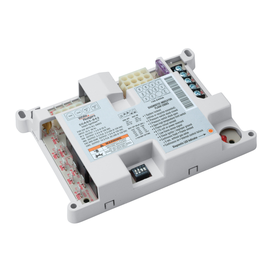
The 50A65-843 is an automatic gas interrupted ignition control that employs a
microprocessor to continually monitor, analyze, and control the proper opera-
tion of the gas burner, inducer, and fan.
Signals interpreted during continual surveillance of the thermostat and flame
sensing element initiate automatic ignition of the burner, sensing of the flame,
and system shut-off during normal operation.
These controls incorporate system fault analysis for quick gas flow shut-off,
coupled with automatic ignition retry upon sensing a fault correction.
Installation should be done by a qualified heating and air
conditioning contractor or licensed electrician.
If in doubt about whether your wiring is millivolt, line, or low
voltage, have it inspected by a qualified heating and air condi-
tioning contractor or licensed electrician.
Do not exceed the specification ratings.
All wiring must conform to local and national electrical codes and
ordinances.
This control is a precision instrument, and should be handled
carefully. Rough handling or distorting components could cause
the control to malfunction.
Following installation or replacement, follow manufacturer's
recommended installation/service instructions to ensure proper
operation.
CAUTION
Do not short out terminals on gas valve or primary
control. Short or incorrect wiring may damage the
thermostat.
CONTENTS
Description ........................................................ 1
Precautions ....................................................... 1
Specifications .................................................... 2
Installation ......................................................... 3
Operation .......................................................... 6
Mounting Hole Template .................................... 8
50A65-843
Universal Integrated Furnace Control
INSTALLATION INSTRUCTIONS
WARNING
Failure to comply with the following
warnings could result in personal injury
or property damage.
FIRE HAZARD
• Do not exceed the specified voltage.
• Protect the control from direct contact with water
(dripping, spraying, rain, etc.).
• If the control has been in direct contact with water,
replace the control.
• Label all wires before disconnection when servic-
ing controls. Wiring errors can cause improper
and dangerous operation.
• Route and secure wiring away from flame.
SHOCK HAZARD
• Disconnect electric power before servicing .
• Ensure proper earth grounding of appliance.
• Ensure proper connection of line neutral and line
hot wires.
EXPLOSION HAZARD
• Shut off main gas to appliance until installation is
complete.
DESCRIPTION
PRECAUTIONS
PART NO. 37-6270E
Replaces 37-6270D
0701
Advertisement
Table of Contents

Related Manuals for White Rodgers UNIVERSAL INTEGRATED FURANCE CONTROL 50A65-843


Summary of Contents for White Rodgers UNIVERSAL INTEGRATED FURANCE CONTROL 50A65-843
-
Page 1: Table Of Contents
Operator: Save these instructions for future use! FAILURE TO READ AND FOLLOW ALL INSTRUCTIONS CAREFULLY BEFORE INSTALLING OR OPERATING THIS CONTROL COULD CAUSE PERSONAL INJURY AND/OR PROPERTY DAMAGE. The 50A65-843 is an automatic gas interrupted ignition control that employs a microprocessor to continually monitor, analyze, and control the proper opera- tion of the gas burner, inducer, and fan. -
Page 2: Specifications
SPECIFICATIONS ELECTRICAL RATINGS [@ 77°F (25°C)]: Input Voltage: 25 VAC 50/60 Hz Max. Input Current @ 25 VAC: 0.45 amp Relay Load Ratings: Valve Relay: 1.5 amp @ 25 VAC 50/60 Hz 0.6 pf Ignitor Relay: 2.0 amp @ 120 VAC 50/60 Hz (resistive) Flame Current Requirements: Minimum current to insure flame detection: 1 µa DC*... -
Page 3: Installation
WARNING FIRE HAZARD • Do not exceed the specified voltage. • Replace existing control with exact model and dash number. • Protect the control from direct contact with water (dripping, spraying, rain, etc.). • Label all wires before disconnection when servic- ing controls. -
Page 4: Typical System Wiring Diagram
(LINE) HUMIDIFIER ELECTRONIC AIR CLEANER FLAME SENSOR PROBE LEGEND Low Voltage (24 VAC) Line Voltage (120 VAC) N. C. = Normally closed switch N. O. = Normally open switch TYPICAL SYSTEM WIRING DIAGRAM 120 VAC 24 VAC CLASS II TRANSFORMER 24 VAC 50A65-843 COOL... -
Page 5: Typical System Wiring Table
TYPICAL SYSTEM WIRING TABLE 50A65 TERMINAL TERMINAL TYPE Terminal block with captive screws MV (2 terminals) 12-pin connector & harness (1 unused terminal) 4-pin connector IND N & harness IGN N COOL spade terminal HEAT spade terminal PARK (2 terminals) spade terminal LINE spade terminal... -
Page 6: Operation
OPERATION OPTION SWITCHES The option switches on the 50A65-843 control are used to determine the length of the cool delay-to-fan-off, heat delay-to- fan-on and heat delay-to-fan-off periods. The following table shows the time periods that will result from the various switch positions. - Page 7 SYSTEM LOCKOUT AND DIAGNOSTIC FEATURES SYSTEM LOCKOUT FEATURES When system lockout occurs, the gas valve is de-energized, the circulator blower is energized at heat speed, and, if flame is sensed, the inducer blower is energized. The diagnostic indica- tor light will flash or glow continuously to indicate system status. (System lockout will never override the precautionary fea- tures.) To reset the control after system lockout, do one of the...
-
Page 8: Mounting Hole Template
MOUNTING HOLE TEMPLATE MOUNTING HOLE TEMPLATE FOR MOUNTING HOLE LOCATIONS 4.172 ± .007 (2 plcs.) 6.402 ± .010 (2 plcs.) Refer to page 3 of the installation instructions for proper installation.