Sony SRR1 Operation Manual
Portable memory recorder
Hide thumbs
Also See for SRR1:
- Operation manual (109 pages) ,
- Software upgrade (11 pages) ,
- Brochure (17 pages)
Table of Contents
Advertisement
Quick Links
Download this manual
See also:
Operating Manual
Advertisement
Table of Contents

Related Manuals for Sony SRR1


Summary of Contents for Sony SRR1
- Page 1 PORTABLE MEMORY RECORDER SR-R1 Sony Corporation SR-R1 Printed in Japan [English] OPERATION MANUAL (SY) 2011.11 32 1st Edition (Revised 1) 4-400-203-02 (1) © 2011 Printed on recycled paper.
- Page 2 Before operating the unit, please read this manual thoroughly and retain it for future - Reorient or relocate the receiving reference. antenna. - Increase the separation between the equipment and receiver. WARNING - Connect the equipment into an outlet on a circuit different from that to which the receiver is connected.
- Page 3 For the customers in Europe Avant d'utiliser l'appareil, veuillez lire attentivement ce manuel et le conserver The manufacturer of this product is Sony pour future référence. Corporation, 1-7-1 Konan, Minato-ku, Tokyo, Japan. The Authorized Representative for EMC and AVERTISSEMENT product safety is Sony Deutschland GmbH, Hedelfinger Strasse 61, 70327 Stuttgart, Afin de réduire les risques...
- Page 4 Um die Gefahr von Bränden télévision). oder elektrischen Schlägen Pour les clients en Europe zu verringern, darf dieses Le fabricant de ce produit est Sony Gerät nicht Regen oder Corporation, 1-7-1 Konan, Minato-ku, Tokyo, Japon. Feuchtigkeit ausgesetzt Le représentant autorisé pour EMC et la werden.
- Page 5 (kommerzieller und in beschränktem Maße industrieller Bereich), E3 (Stadtbereich im Freien) und E4 (kontrollierter EMV-Bereich, z.B. Fernsehstudio). Für Kunden in Europa Der Hersteller dieses Produkts ist Sony Corporation, 1-7-1 Konan, Minato-ku, Tokyo, Japan. Der autorisierte Repräsentant für EMV und Produktsicherheit ist Sony Deutschland GmbH, Hedelfinger Strasse 61, 70327 Stuttgart, Deutschland.
-
Page 6: Table Of Contents
Table of Contents Locking the Controls ....26 Chapter 1 : Overview Signal Format Settings......27 Features........... 8 Selecting the Signal Format..27 System Configuration Example .... 9 Display Settings ........28 Using the Backlight ....28 Names of Parts........10 Using the Screen Saver.... - Page 7 Chapter 5 : Menu Details TC Setup Menu ........41 AUDIO Setup Menu ......44 SYSTEM Setup Menu ......46 Appendix Maintenance and Inspections....49 Note About the Power Supply Terminal ......49 Specifications ........49 General ........49 Video ......... 50 Audio .........
-
Page 8: Chapter 1 : Overview
4:4:4 and 60p to enable support for various scenes. HD SDI Remote Support is provided for the HD SDI Remote function that is incorporated in many Sony camcorders, so recording can be linked to Rec/ Stop on the camera side. HDW-F900R/650 dockable operation... -
Page 9: System Configuration Example
System Configuration Example The following figure shows a system configured around the SR-R1. HD color video camera BP-GL95 BKP-L551 Earphones/ HD VTR etc. Headphones AC-DN10 DC IN HD SDI video/ audio input Audio input Microphone HD SDI video/audio output Analog: 2 channels HD VTR etc. -
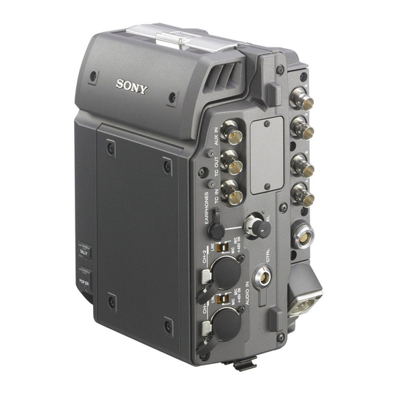
Page 10: Names Of Parts
Left Side View Names of Parts For detailed information on functions and usage, see the pages indicated in brackets. Overall View 10 9 AUDIO INPUT CH-1, CH-2 (analog audio input channel 1, 2) connectors (3-pin XLR, female) and input selection switches Set the input selection switches as follows, depending on the type and level of the input audio. -
Page 11: Rear And Right Side View
REMOTE (remote control input) connector (14-pin, female) (for future expansion) DC IN (DC power input) connector (4-pin XLR, male) (page 16) CTRL PANEL (Control Panel) connector (page 16) Rear and Right Side View Power switch (page 22) Setting the switch to the ? side turns power on, and setting the switch to the 1 side turns power off. -
Page 12: Control Panel
Control Panel For information on how to use the control panel, see “Basic Menu Operations” (page 25). KEY INHI HOME SELECT/ENTER LIGHT BACK SR-R1 VIDEO STOP ADJUST KEYINHI RECINHI AUDIO EJECT STOP PLAY SYSTEM LOCAL F FWD PAUSE ENCODE 1920x1080 16.5V REMAIN FUNC... -
Page 13: Display
Display The condition shown below is called the HOME screen in this manual. Sections 4 to 7 change to the condition shown as 10 below when the HOME button is pressed while holding down the FUNC button. SYS: 1920x1080 59.94I 4:2:2 LOCAL ENCODE: SR-SQ 10bit 60min... - Page 14 SRMemory card remaining capacity indication (page 23) Shows the remaining space on the SRMemory card calculated as remaining time, using the current recording settings. When the remaining time is less than 3 minutes, the indication flashes. Battery/External power supply voltage indication (page 22) Shows the battery or external power supply voltage.
-
Page 15: Chapter 2 : Preparation
Preparation Chapter Work Flow Mount Control Panel The steps that are required before starting to use Attach the supplied CP bracket to the unit, and the SR-R1 are listed below. connect the unit and the control panel with the control panel cable. Mount control panel (page 15) Attach the supplied CP bracket to the Connect power (page 16) -
Page 16: Connect Power
The SR-R1 can be powered either from a battery pack or AC power. For safety, do not use any AC adapter or battery pack other than the Sony products specified below. • AC adapter: AC-DN10 • Lithium ion battery pack: BP-GL95... - Page 17 ATTENTION Attach the supplied BKP spacer. Il y a danger d’explosion s’il y a remplacement The S symbol must face up. incorrect de la batterie. Remplacer uniquement avec une batterie du même type ou d’un type S symbols équivalent recommandé par le constructeur. Lorsque vous mettez la batterie au rebut, vous devez respecter la législation en vigueur dans le pays ou la région où...
- Page 18 Align the line on the side of the battery Lock release button pack with the line on the unit and place the battery pack on the rear section of the unit. 1 Battery pack 2 Main unit/battery pack line Notes •...
-
Page 19: Connect Hd Sdi Compliant Equipment
Connect HD SDI Compliant Equipment Connect equipment with an HD SDI interface to the HD SDI IN (MON) (HD SDI signal input) connector A/B and HD SDI OUT (HD SDI output) connector A/B of the SR-R1. Representative connection examples are shown below. Connecting a Camera/Camcorder Using the HDW-F900R or similar to record a 4:2:2 signal SR-R1... -
Page 20: Connecting An Hd Monitor
Connecting an HD Monitor HD monitor SR-R1 HD video input HD SDI HD SDI OUT (MON) 1 Connecting a RGB4:4:4 and 1080 50p/60p (Dual Link) compatible HD monitor BVM-E250 HD Monitor SR-R1 LINK B IN LINK A IN HD SDI OUT (MON) 2 HD SDI OUT (MON) 1 Connect HD SDI Compliant Equipment... -
Page 21: About The Reference Sync Signal
About the Reference Sync Signal External synchronization required If external synchronization is required, connect an HD SDI signal synchronized to the reference signal. Recording/playback with synchronized camera, switcher, signal generator etc. Reference signal SR-R1 REF IN, GENLOCK IN Camera, switcher, signal generator etc. -
Page 22: Turn Power On
• The voltage shown is the actual voltage used by the Turn Power On unit (this may be lower than the input voltage and the DC IN connector). When a battery pack is selected The battery symbol is shown. 16.5V To power up the unit When using the AC adapter, turn •... -
Page 23: Insert Srmemory Card
Insert SRMemory Card SRMemory card Supported SRMemory cards The SR-R1 can use the following types of SRMemory cards. If the LID LOCK indicator is lit in orange, showing that the lid is locked, press the EJECT button on the control panel to unmount the card first, and then For 59.94i open the lid. -
Page 24: Formatting An Srmemory Card (File System Format )
To remove the SRMemory card Formatting an SRMemory Card (File System Format ) Press the EJECT button on the control panel while power to the unit is on. SRMemory cards are sold already formatted, so The files in the SRMemory card are closed you can use a newly purchased SRMemory card automatically, the SRMemory card is right away. -
Page 25: Chapter 3 : Basic Menu Operations
Basic Menu Operations Chapter The menu system of the SR-R1 consists of the Serve for Selecting a Menu following four menus. Menu Overview Selecting a menu TC Setup Serves for making time code Press the respective menu selection button. settings. TC: Brings up the TC Setup menu. -
Page 26: Locking The Controls
Rotate the SELECT/ENTER dial to Locking the Controls move the cursor to the target item, and press the SELECT/ENTER dial. To prevent operation errors or an inadvertent Submenu window change in settings, the controls of the unit can be locked. T C S e t u p Access the SYSTEM Setup menu and set KEY TCG Setting(Main) -
Page 27: Signal Format Settings
Signal Format Settings S Y S T E M S e t u p Signal Format FILE LIST FRAME 29.97 SIGNAL FORMAT SIGNAL TEST SG SELECT FPS KEY MAP FPS FORMAT 23/24 KEY INHI ENCODE SR-Lite REC INHI [SET] POWER BATTERY SRMemory OTHERS... -
Page 28: Display Settings
Display Settings Date Settings You can make settings for backlight use in dark Display the System menu and select OTHERS locations, screen saver, etc. >SET DATE menu to set the date and time of the unit. Using the Backlight To set the date and time (OTHERS >SET DATE menu) Setting the LIGHT switch to ON turns the backlight on. -
Page 29: Recording Preparations And Operations
Recording and Playback Chapter Preparation Operation Reference Recording Preparations Set time code RUN MODE, page 32 generator TCG MODE, and and Operations operation in REGENE accordance with SOURCE in the the time code and TC Setup user bits to record. menu Before recording, make the following Configure the other related menu settings as... -
Page 30: Setting The Recording Levels
ANA1 to ANA2: Analog signals input via To set the mixing mode for audio signals the AUDIO INPUT CH-1 and CH-2 Display the AUDIO Setup menu and then connectors 1 select and confirm “MIX MODE” Set the signal to record for each of the t2 select and confirm the mixing mode. -
Page 31: Setting The Time Code And User Bits
Move the cursor to and select this 2 Scale setting 1 METER TYPE Recording levels method R e c L e v e l A U D I O S e t u p INPUT SEL PHONE SEL MIX MODE REC LEVEL PB LEVEL METER TYPE... - Page 32 TM1/TM2: Displays the timer value of Timer 1 or Timer 2. To select the time code to record The time code can be selected in the following menu. Menu item Time code TCG MODE REGENE SOURCE PRST — An arbitrary time code can be set. (R RUN/F RUN and DF/NDF can be set to an arbitrary value in the menu.) EXT L In accordance with the time code input via the TC IN connector.
-
Page 33: Recording
Use the following method to synchronize the time To record the time code code generators of multiple VTRs. The following methods are available for recording the time code. Display the TC Setup menu and then set “TCG • Set the initial value and record the time code. MODE”... -
Page 34: Playback Preparations And Operations
• Check that the write-protect switch for the Playback Preparations SRMemory card is not in the WP position. and Operations Press the PLAY button while holding down the REC button. Recording starts, and “REC LOCK” appears. Press the STOP button to stop Making Settings Related to Audio recording. -
Page 35: Playback
Playback Insert the SRMemory card to play back. For details, see “To insert the SRMemory card” (page 23). Press the PLAY button. Playback starts and the PLAY LOCK indication lights up. Press the STOP button when you want to stop playback. Playback Preparations and Operations... -
Page 36: How To Use The Recording And Playback Operation Buttons
How to Use the Recording and Playback Operation Buttons Button Function when pressed alone Function when pressed with FUNC button STOP button Stops the recording and playback — operation. PLAY button and indicator Starts playback. (The indicator is lit — during playback.) To start recording, press this button while holding down the REC button. -
Page 37: Making Superimpose Settings
“PLAY PAUSE” Making Superimpose “F.FWD” “REW” Settings “UNMOUNT” “STOP” c Remaining amount of recording time on SRMemory card Time codes, operating modes, warning/error messages, and other text information can be d Drop frame mark of the time code superimposed on (added to) the video signals reader output from the HD SDI OUT (MON) “... -
Page 38: File List Operations
When a warning/error message is not being FILE LIST Operations displayed, the information selected in CHAR > MODE in the TC Setup menu flashes on the second line. To change the superimpose position The superimpose position can be moved to 16 “FILE LIST”... -
Page 39: Performing File Operations
Display when the SRMemory card contains no Displayed information files F i l e l i s t [0/0] Icon File list <\> Cusor No file data F i l e l i s t [4/7] <\> [ F i l e N a m e ] [ D a t e ] [ D u r a t i o n ] F I L E 0 0 0 0 0 0 0 1... -
Page 40: Changing The File Display Order
To rename a file Select and confirm RENAME to display the file rename screen. Rename the file and then move the cursor to and confirm [END] to apply the file name. To cancel the change Press the BACK button to return to the File list screen. -
Page 41: Chapter 5 : Menu Details
Menu Details Chapter • The settings displayed in bold are the factory default settings. • The settings enclosed in [] are the settings as displayed in the settings windows. TC Setup Menu Setting Item Settings TIMER SEL Selects the type of time data to display on the display. TC [Time Code]: Displays the time code: Displays the time code. - Page 42 Setting Item Settings REGEN SRC Selects the time code to be synchronized (regenerated) by the internal time code generator. EXT L [External LTC]: Time code input to the TC IN connector SDI L [SDI LTC]: LTC time data of video signal input to the HD SDI IN connectors A SDI V [SDI VITC]: VITC of video signal input to the HD SDI IN connectors A...
- Page 43 Setting Item Settings CHAR ON/OFF Sets whether or not to output text information. Settings related to the ON [On]: Outputs. text information OFF [Off]: Does not output. superimposed on the HPOS Sets the display position of text information in the output from the HD horizontal direction.
-
Page 44: Audio Setup Menu
AUDIO Setup Menu Setting Item Settings INPUT SEL TRACK1 Selects the signal to assign to track 1. Selection of input SDI1 [SDI CH1] to SDI16 [SDI CH16], signals ANA1 [Analog CH1] to ANA2 [Analog CH2], AUX1 [AUX SDI CH1] to AUX16 [AUX SDI CH16] TRACK2 Selects the signal to assign to track 2. - Page 45 Setting Item Settings REC LEVEL Adjusts the recording level (see page 31). (This adjustment is not possible during playback.) PB LEVEL Adjusts the playback level (see page 34). (This adjustment is not possible during recording.) METER TYPE Sets the display range of the audio level meters. PEAK [Full Peak]: Displays 0 dBFS as the peak value.
-
Page 46: System Setup Menu
SYSTEM Setup Menu Setting Item Settings FILE LIST FILE LIST Displays a list of recording files and allows recording files to be selected and file operations to be performed. For details, see “FILE LIST Operations” (page 38). SORT Sorts the files in the FILE LIST screen. DATE: Date order NAME: Name order DURATION: Order of file recording length... - Page 47 Setting Item Settings LIGHT OFF Sets whether or not to turn the backlight off after a set Settings of display time. backlight DIS [Disable]: Does not turn the backlight off. 5sec [5sec]: Turns the backlight off after 5 seconds. 10sec [10sec]: Turns the backlight off after 10 seconds. 30sec [30sec]: Turns the backlight off after 30 seconds.
- Page 48 Setting Item Settings BATTERY DCIN TYPE Selects the type of battery to be connected to the DC IN Settings related to the connector. remaining battery AC [AC Adapter]: AC adapter power indication Li-ion [Li-ion Battery]: Lithium ion battery BP-GL [BP-GL Battery]: BP-GL95 OTH1 [Other 1] OTH2 [Other 2] Near END...
-
Page 49: Appendix
4 °F to +140 °F) –20 °C to +60 °C – usable lifetime. Contact a Sony service or sales Operating relative humidity representative for more information about 10% to 95% (no condensation) inspections. -
Page 50: Video
Analog audio input A/D quantization 24 bits Reference input level LINE: +4 dBu MIC: –34 dBV Frequency response 20 Hz to 20 kHz +0.5 dB/–1.0 dB (at reference level) Dynamic range More than 100 dB (1 kHz) Distortion Less than 0.05% (1 kHz, at reference level) Crosstalk Less than –80 dB (1 kHz, between any two channels) -
Page 51: Supplied Accessories
BKP spacer (1) • Always verify that the unit is operating properly CP bracket (1) before use. SONY WILL NOT BE LIABLE FOR Control panel cable (0.6 m) (1) DAMAGES OF ANY KIND INCLUDING, BUT REMOTE cable (1) (for future expansion) -
Page 52: Error Messages And Warning Messages
When a warning message appears If the same error message appears again when the Take any action that may be needed to eliminate system is powered on, contact a Sony service the cause of the warning. representative. Error Messages and Warning Messages... -
Page 53: Warning System
An error occurred. Operation Check the error continues or message, and resolve stops, the condition. depending on Alternatively, contact a the type of Sony service error. representative. — SRMemory card is Operation Prepare to replace almost full. continues. SRMemory card. -
Page 54: Troubleshooting
A warning massage and a message asking Troubleshooting whether you want to perform salvaging or formatting appears on the display. Notes • If REC inhibit is set to “ON” in the SYSTEM menu, set it to “OFF.” • After you start the salvaging process, the process cannot be stopped. - Page 55 Video Problem Cause Countermeasures Picture is gray. No input signal is being supplied to Supply the input signal for the selected system HD SDI IN connector A. format to HD SDI IN connector A. No input signal is being supplied to To enable use of the 4:4:4 format, input a HD SDI IN connector B(when signal with the correct format to HD SDI IN...
- Page 56 Audio Problem Cause Countermeasures • No sound. Level meter indication is flashing, Set up input device correctly to supply an SDI • “AUDIO PLL and input is disabled. or AUX audio signal. UNLOCK” is Mode was switched. To prevent noise and damage to audio monitor displayed.
- Page 57 Problem Cause Countermeasures Power to other Power switch of other equipment is Turn power switch of other equipment on. equipment does not not on. come on. Low voltage. The power cable is too long, If the power cable is too long or does not have causing a voltage drop.
-
Page 58: About Recording/Playback Formats
About Recording/Playback Formats Number of lines Signal Scanning system System frame Encoding frequency SR-SQ SR-Lite 10bit 10bit 1280 × 720 Progressive — — — — 1920 × 1080 Interlaced 29.97 23.98 29.97 Progressive 59.94 1920 × 1080 Interlaced — 29.97 —... -
Page 59: Mpeg-4 Visual Patent Portfolio License
MPEG-4 VISUAL PATENT PORTFOLIO LICENSE THIS PRODUCT IS LICENSED UNDER THE MPEG-4 VISUAL PATENT PORTFOLIO LICENSE FOR THE PERSONAL AND NON- COMMERCIAL USE OF A CONSUMER FOR (i) ENCODING VIDEO IN COMPLIANCE WITH THE MPEG-4 VISUAL STANDARD (“MPEG-4 VIDEO”) AND/OR ii) DECODING MPEG-4 VIDEO THAT WAS ENCODED BY A CONSUMER ENGAGED IN A PERSONAL AND NON-COMMERCIAL... -
Page 60: Index
File system format 24 Index FORMAT 46 HD SDI IN connectors A/B 10 HD SDI OUT connectors A/B 10 Accessories supplied 51 ADJUST knob 12 INPUT DELAY 45 Adjusting playback audio levels 34 INPUT SEL 44 AUDIO INPUT CH-1, CH-2 connectors 10 AUDIO INPUT CH-1, CH-2 input selection switches 10 Audio level meters 13... - Page 61 POWER 47 TIMER RESET 41 POWER (power supply) indicator 10 TIMER SEL 41 Power supply 16 Troubleshooting 54 REC INHI 47 User bits 31 REC LEVEL 45 Recording 33 Recording and playback operation buttons 12, 36 Warning system 53 Recording preparations 29 Recording/playback formats 58 Reference signal 21 REGEN SRC 42...
- Page 63 The material contained in this manual consists of information that is the property of Sony Corporation and is intended solely for use by the purchasers of the equipment described in this manual. Sony Corporation expressly prohibits the duplication of any portion of this manual or the...