Sony PMW-1000 Operation Manual
Memory recoder
Hide thumbs
Also See for PMW-1000:
- Brochure (2 pages) ,
- Operation manual (62 pages) ,
- Service manual (166 pages)
Table of Contents
Advertisement
Quick Links
Advertisement
Table of Contents

Related Manuals for Sony PMW-1000


Summary of Contents for Sony PMW-1000
- Page 1 MEMORY RECODER PMW-1000 OPERATION MANUAL [English] 1st Edition...
-
Page 2: Table Of Contents
Attaching a battery pack..............20 Initial Setup ..................22 Connections and Settings ............23 Connections for Content Browser and non-Sony nonlinear editors..23 Connections for cut editing ..............24 Using the editing functions of the recorder (controlling through REMOTE(9P) connector) ............27 Connections for pool coverage............ - Page 3 Handling an External Storage ............39 Using the external storage ..............39 Removing the external storage ............40 Chapter 4 Recording, Playback and Copy Recording..................41 Preparations for recording ..............41 Carrying out recording................. 41 Recording with the HDSDI remote control function......42 Handling of SxS memory cards when recording does not end normally (salvage functions) ..............
- Page 4 Chapter 6 File Operations Overview..................66 Directory structure................66 File operation restrictions ..............66 FTP File Operations............... 67 Making FTP connections..............67 Command list ..................68 CIFS File Operations ..............71 Making CIFS connections ..............71 Chapter 7 Menus Menu System Configuration ............72 Setup Menu ..................
-
Page 5: Table Of Contents
Character display software “iType”........... 106 Open software licenses ..............106 Obtaining GPL/LGPL/GPL V3 licensed software ......107 Index .................... 108 Table of Contents... -
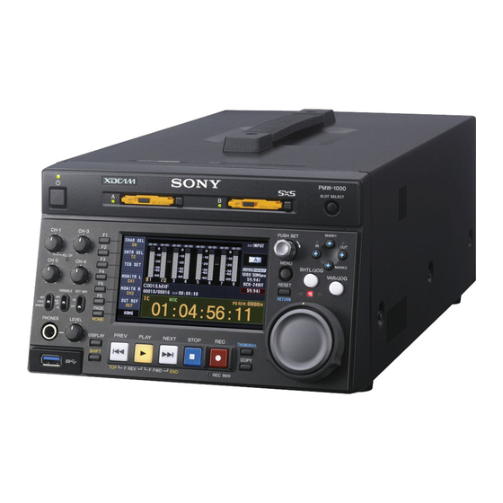
Page 6: Chapter 1 Overview
Overview Chapter Uncompressed PCM recording of 24-bit 48 kHz audio Features enables 8-channel audio recording at high sound quality. Recording and playback functions The PMW-1000 is a full-HD (1920 × 1080 and 1280 × Support for MPEG/XAVC/SD with multiple codecs 720) memory recorder. - Page 7 When the unit is used with a PC connection, download Usability features device drivers, plug-ins, and application software, where applicable, from the Sony Professional products web site. AC, DC, and battery power support The unit can be used even where AC power is not Sony Professional products and solutions site homepage: available, for example outdoors or in cars or helicopters.
-
Page 8: System Configurations
System Configurations SxS memory cards PDW-700/PMW-500 PDW-1500 BP-L80S Battery Pack RM-280 editing BKP-L551 battery controller adaptor DC power source AC power source BVE-700 SD video monitor Headphones HD video monitor HDW-2000 series Audio monitor PDW-F75 Laptop computer a) For HDW-2000 series only. System Configurations... -
Page 9: Chapter 2 Names And Functions Of Parts
Names and Functions of Parts Chapter Front Panel The names and symbols of buttons and knobs on the front Orange: Function when the button is operated with the panel are color coded according to function. SHIFT button held down. White: Function when the button or knob is operated Blue: Function related to thumbnail operations. - Page 10 b Remote control switch 1 Memory card slots Different positions of the switch allow different operations as follows. Eject buttons NET: Enables access to the network. The indicator lights when an external network device is being accessed. In this state, it is not possible to perform recording and playback on this unit using its buttons/dials.
- Page 11 4 Shuttle/jog/variable control section PB: Adjust the playback audio levels. The input audio levels are fixed at their preset values. SHTL/JOG button 3 Arrow buttons The four arrow buttons are also used as the MARK1 VAR/JOG button button, MARK2 button, IN button, and OUT button. The SHTL/JOG VAR/JOG correspondence with these buttons is as follows.
-
Page 12: Menu Button
c PUSH SET knob PAGE button: Displays the function menu, if it is not Use for menu and clip list screen operations. Turn the knob already visible. (The most recently displayed page of to select items, and press it to confirm the selection. This the function menu appears.) button is also used to set numerical and timecode values. -
Page 13: Display Screen
To monitor in EE mode Note You can press this button from stop mode to monitor input signals in EE mode. The button lights when pressed. Press This button flashes when setup menu item 105 the STOP button to return to the original video. REFERENCE SYSTEM ALARM is set to “on”... -
Page 14: System Information
b Audio input display/audio level meters c System information Displays information about audio. A Reference signal A Input signal display B Video input display B Data indication A Reference signal: This displays the type of reference signal to which this unit is synchronizing. When there is no display, the unit is synchronizing to the internal reference signal. -
Page 15: Status Display
f Clip information D VITC: Lights in the following cases. Displays clip information. • When VITC is read in playback mode. (This has no relations to the display in the time data display area.) Clip number/total number of clips • When VITC recording is possible. Clip name Duration E Time data type: Displays the type of time data... -
Page 16: Video Monitor Screen
Video monitor screen B Delete icon: Flashes while a clip deletion is being executed. C Copy icon: During a clip copy operation, displays an A Superimposed information icon indicating the copy source/copy destination media. Icon Copy source/copy destination media SxS memory card/SxS memory card External storage/SxS memory card SxS memory card/external storage TCR.00:45.39.18*... -
Page 17: Rear Panel
Rear Panel 6 DC IN 12V connector 1 Power supply section (see page 18) 7 REMOTE connector 2 Analog audio signal input/ output section (see page 18) 1 HDMI OUT connector 8 COMPOSITE OUTPUT 1, 2 (SUPER) connectors 2 SD/HDSDI INPUT connector 9 REF. - Page 18 (D-sub 9-pin) Connect a controller that supports the VDCP protocol or 1 POWER switch the RS-422A Sony 9-pin VTR control protocol. 2 - AC IN connector f DC IN 12V connector (XLR 4-pin, male) Connect to a DC power source of 12 V.
- Page 19 b ANALOG AUDIO OUTPUT 1, 2 connectors (XLR 3-pin, male) These output analog audio signals. When the unit is shipped from the factory, the 1 connector is set to audio channel 1, and the 2 connector is set to audio channel 2.
-
Page 20: Chapter 3 Preparations
CPU in the standby battery pack. state even when the unit is not powered. For safety, use only the Sony battery packs listed below. • Before using the batteries, be sure to charge them fully Lithium-ion battery pack: BP-L80S with the special battery charger. - Page 21 Checking the remaining battery power Attach the BKP-L551 to the side panel. You can use the LEDs on the side panel of the battery to check the remaining power of the battery. When the remaining battery power decreases substantially and the voltage approaches the set shutdown voltage, the power source icon starts flashing in the status display area of the display screen (the battery near end alarm is given).
-
Page 22: Initial Setup
Turn the PUSH SET knob to select the system Initial Setup frequency. This unit is shipped with the system frequency, recording format, and current date and time still unset. Therefore, you need to make initial setup settings before using the unit. (You cannot use the unit without setting it up.) Once the unit has been set up, the settings are retained even when the unit is powered off. -
Page 23: Connections And Settings
(network) You can also access to this unit from a nonlinear editor that connector is not a Sony product via FTP/CIFS, and use this unit as a material server. CAUTION For an overview and installation of Content Browser, When you connect the Network cable of the unit to access the Sony website closest to your area. -
Page 24: Connections For Cut Editing
2: 9-pin remote control cable (not supplied) HD video monitor 3: HDMI cable (not supplied) Recommend to use an optional Sony HDMI cable. a) You can use setup menu item 161 (see page 80) to set which signal to output from the HDMI OUT... - Page 25 HDW-M2000 (recorder) settings BVE-700/700A (editing control unit) setting Settings on this unit REMOTE 1 (9P) button: Lit SYNCHRONIZE menu:OFF Remote control switch: REMOTE (see page 10) REF.VIDEO INPUT connector 75 Ω termination Setup menu item 214 switch: OFF REMOTE INTERFACE: 9PIN Audio selection function switching button INPUT button: HDSDI...
- Page 26 2: 9-pin remote control cable (not supplied) HD video monitor 3: HDMI cable (not supplied) Recommend to use an optional Sony HDMI cable. a) You can use setup menu item 161 (see page 80) to set which signal to output from the HDMI OUT...
-
Page 27: Using The Editing Functions Of The Recorder (Controlling Through Remote(9P) Connector)
3: HDMI cable (not supplied) connector: the same signal as the HDSDI OUTPUT 2 (SUPER) connector output, or the HDSDI signal and thumbnails view signal by automatically switching Recommend to use an optional Sony HDMI cable. between them. Connections and Settings... -
Page 28: Connections For Pool Coverage
For details of HDW-M2000/M2000P settings, refer to the HDW-M2000 (recorder) Settings on this unit HDW-M2000/M2000P Operation Manual. setting REMOTE 1 (9P) button: Remote control switch: Unlit REMOTE (see page 10) Setup menu item 214 REMOTE INTERFACE: 9PIN Connections for pool coverage The following figure shows an example of connections for PDW-700 (camcorder) Settings on this unit... -
Page 29: Synchronization Reference Signals
Synchronization Reference Signals The synchronization reference signal generator of this unit setting of OUT REF on the HOME page of the function synchronizes to a reference signal input to the REF. menu, and on the type of the selected input signal. Video VIDEO INPUT connector or to a video input signal. -
Page 30: Setting System Frequency
Setting System Setting Timecode Frequency There are the following four ways of recording timecode: Internal Preset mode: This records the output of the This unit can record and play back video at the system internal timecode generator, set beforehand to an frequencies of 1080/59.94i, 50i, 29.97P, 25P, 23.98P or initial value. -
Page 31: Setting User Bits
Setting user bits Press the TCG SET function button (F3). You can record up to 8 hexadecimal digits of information The first digit of the time data display starts flashing. (date, time, event number, etc.) on the timecode track. Select UB by pressing the CNTR SEL function button (F2) in step 1 of “Setting an initial timecode value”... -
Page 32: Superimposed Text Information
Make the following settings on page P4 TC of the Superimposed Text function menu. • Set TCG to “SDI”. Information • Set PRST/RGN to “TC”. Executing either of these procedures starts the internal The video signal output from the COMPOSITE OUTPUT timecode generator running in synchronization with the 2 (SUPER) connector, SDSDI OUTPUT 2 (SUPER) external timecode generator. - Page 33 a Type of time data Display Operation mode Display Meaning Block A Block B Counter data PLAY Playback mode (servo unlocked) TC reader timecode PLAY LOCK Playback mode (servo locked) TC reader user bits data Record mode (servo unlocked) TCR. VITC reader timecode LOCK Record mode (servo locked)
-
Page 34: Basic Operations Of The Function Menu
To change the setting of a function menu Basic Operations of the item Use the function buttons. Function Menu To select the value of the setting item Press the button to the left of each setting item to change The function menu provides access to frequently used the value of the item. -
Page 35: P2 Input Page
P2 INPUT page Item Setting F5: MONITR R Selects the channel to monitor as the right Item Setting monitor channel. F1: A5 INPUT Selects the audio input signal to assign to CH1, CH2, CH3, CH4, CH5, CH6, CH7, audio channel 5. SDI: Audio signal embedded into SDI CH1/2, CH3/4, CH5/6, CH7/8 (MIX) signal... -
Page 36: P4 Tc Page
Item Setting Item Setting F4: A8 VOL Sets the volume of audio channel 8. F5: PDPSET When the system frequency is set to 1080/ The volume can be adjusted within the 59.94i, 1080/29.97P, or 720/59.94P, range from –200 to 0 to +200 (–∞ to presets the timecode of the A frame of the +12 dB) by turning the PUSH SET knob. -
Page 37: Handling Memory Cards
Note unit Do not touch the write protect switch while an SxS Use the following Sony memory cards with this unit. memory card is loaded in a memory card slot. Eject the card before setting the write protect switch. SxS PRO+... -
Page 38: Switching Between Sxs Memory Cards
To insert an SxS memory card Press the eject button again to remove the card. Insert the SxS memory card into the card slot. Insert with the label side facing upward Note The lamp lights in orange then changes to green once the Data are not guaranteed if the power is turned off or a memory card is ready for use. -
Page 39: Handling An External Storage
USB DRV (OFF) (see page 57). information about recommended devices, consult your The processing for USB drive mounting starts. Sony dealer. When the USB drive gets mounted, the “OFF” indication under F1: USB DRV changes to “ON” and It is possible to create up to 99 folders on the external... -
Page 40: Removing The External Storage
To create a new folder Press F3: CREATE FOLDER. To copy clips to the external storage Mount the USB drive. You can use F4: CREATE USB FLDR in the Clip F Menu (see page 56) to create a copy destination folder before Mount the copy destination folder, or create a new executing a copy operation. -
Page 41: Chapter 4 Recording, Playback And Copy
Recording, Playback and Copy Chapter SD up-convert function Recording You can input SD signals to the SD/HDSDI INPUT connector and record them as HD signals. This section describes video and audio recording on the unit. Carrying out recording See page 34 “Basic Operations of the Function Menu” in One recording segment (from the start to the end of Chapter 3 for more information. -
Page 42: Recording With The Hdsdi Remote Control Function
• The shortest clip that can be recorded is 2 seconds long. Recording with the HDSDI remote Even if recording start and stop operations are performed control function within 2 seconds, a 2-second clip is recorded. • The maximum number of clips that can be recorded is This section explains the settings required for recording in 600. -
Page 43: Handling Of Sxs Memory Cards When Recording Does Not End Normally (Salvage Functions)
To restore clips with a full salvage After an SxS memory card is exchanged, the unit resumes operation according to the REC or STOP command embedded in the HDSDI signal. Insert the SxS memory card on which recording did If an SxS memory card is removed when a clip is being not end normally. -
Page 44: Playback
After playback stop Playback The unit stops at the position where the STOP button was pressed. Press the PLAY button to resume playback at the stop position. This section describes playback of video and audio on the unit. After recording The unit stops at the position where recording ended. -
Page 45: Playback Operation
Note When the unit is in continuous playback mode and some clips are selected for pulldown playback, continuous playback of the selected clips is performed in the specified format of pulldown playback (1080/23.98P or 720/ 23.98P). Timecode in pulldown playback During pulldown playback, timecode is also converted to 30-frame timecode to match the output video signals. - Page 46 Note Shot marks cannot be set to a locked clip. Playback in jog mode In jog mode, you can control the speed of playback by the speed of turning the jog dial. The playback speed range is –1 to +1 times normal speed. To carry out playback in jog mode, proceed as follows.
-
Page 47: Playback Operations Using Thumbnails
Playback in variable mode See “Clip Operations” (page 57) for more information about thumbnail. In variable mode, you can control the speed of playback in the range of –2 to +2 times normal speed by the angular position of the shuttle dial. To carry out playback in variable mode, proceed as follows. -
Page 48: Copying
metadata, consisting of video and audio data only) that Copying meet the following conditions. - Clips containing 1000 or more essence marks - Clips containing 10804 or more timecode breaks - Clips with metadata files *M01.XML more than 2 MB Overview in size This unit enables a copy of clips, EDLs, and files to... - Page 49 To copy part of a clip To abort the copy operation When you select a single clip and press the arrow Press the ABORT function button (F1), and then press buttons to set an IN and OUT point in the clip, it the YES (F5) button.
- Page 50 Press the PUSH SET knob while holding down the b/OUT button. An IN/OUT setting window appears in the bottom right corner of the display. The OUT point timecode and the duration (DUR) are displayed in the IN/OUT setting window, and the OUT indicator lights.
-
Page 51: Chapter 5 Operations In Clip List Screens
Operations in Clip List Screens Chapter Overview Use clip list screens to search for scenes, play scenes found You can switch between the details view and the by searching, select clips to copy, and perform other thumbnails view of clip list screens. operations related to clips. -
Page 52: Information And Controls In Clip List Screens
Information and controls in clip list Notes screens • Every character that cannot be displayed properly is represented by a x. • Too long a clip name is not fully displayed. To check the Thumbnails view entire character string of the name, access the Clip Properties screen (see page 53). -
Page 53: Clip Properties Screen
1 Clip storage locations Frame Rate: The frame rate at the time when the clip was shot. For clips shot using Slow & Quick Motion, the 3 Clip number/total number of clips PB (playback)/Capture (shooting) frame rates are 6 Duration shown. -
Page 54: Expand Thumbnail Screen
Note When you cue up a clip, the unit always cues up the first frame, even when the index picture has been changed to a different frame. c Clip flag icon Displays the corresponding icon when a clip flag (OK/NG/ KP(KEEP)) is set in the clip (see page 59). -
Page 55: Clip Menu
g Duration Rec Start essence marks are set automatically at the start of recording, but shot marks can be set at any scene during Displays the time from the first frame of the selected recording or playback. chapter to the first frame of the next chapter. h Scrollbar See page 42 and page 45 for more information about shot mark setting. -
Page 56: Clip F Menu
CLIP page Item Sub-item Function Media Properties – Displays information Item Function about the selected media. F1: CLP INFO Selects the information to be displayed at the bottom of the thumbnails. Settings Select Clip Selects the clip name DATE: Date and time of creation, or date Language display language. -
Page 57: Clip Operations
For the procedure for creating EDLs, see “Creating and Clip Operations editing EDLs” (page 61). P2 OTHER page Selecting clips Item Function F1: USB DRV When an external storage is connected to Select clips with the selection frame (see page 52). this unit, executes USB drive mounting or dismounting. -
Page 58: Playing A Clip By Thumbnail Search
In the clip thumbnail screen, select the thumbnail of Press the PAGE/HOME button to display the function the clip that contains the scene you want to find. buttons, and press the CHAPTER function button (F5). Press the EXPAND function button (F6). The chapter thumbnail screen (see page 54) appears, The selected clip is divided into 12 blocks, and a list with thumbnails of the frames where chapters are set. -
Page 59: Setting Clip Flags
To lock clips Setting clip flags In a clip list screen, select the clips that you want to You can set three types of clip flags (OK/NG/KP(KEEP)) lock (multiple selections possible). for selected clips. Setting these flags in each clip that you record makes it easy for editors and other colleagues to This step is not needed if you lock all clips. -
Page 60: Copying Clips
In a clip list screen, select the clips that you want to Display the page P5 OTHER of the function menu, delete (multiple selections possible). and press the INDEX function button (F1). This step is not needed if you delete all clips. A confirmation box appears asking you whether to set the frame of the still image as the index picture frame. -
Page 61: Edl Editing
EDL Editing Clips on media Clip 1 Clip 2 Clip 3 Clip 4 (C0001) (C0002) (C0003) (C0004) What is EDL editing? EDL (E0001) EDL editing is a function which allows you to select material (clips) from the material recorded on media and Sub clip 1 Sub clip 2 Sub clip 3... - Page 62 Create EDLs: Use the CREATE NEW EDL command to create an EDL containing the selected clips. Add sub clips: Use the ADD TO CURT.EDL command to add the clips you want to use to an EDL. You can add up to 300 sub clips to one EDL. Delete sub clips: Use the REMOVE command to delete specified sub clips from an EDL.
- Page 63 Display the P1 EDL page of the Clip F menu and press the SET CURT.EDL button (F1). The selected EDL becomes the current EDL. When the current EDL is specified, the current EDL icon appears in the status display area. Adding in clip list screens See page 51 for information about screen operations.
-
Page 64: Media Operations
To play an EDL Media Operations In the chapter thumbnail screen, select the thumbnail for the sub clip you want to start playing. To start playing from the first frame of the EDL Checking the media information Select the thumbnail for the first sub clip. In a clip list screen, press the MENU button to display Press the PLAY button. - Page 65 Insert the SxS memory card you want to format into the memory card slot. Press the SLOT SELECT button. When two SxS memory cards are inserted Press the SLOT SELECT button, and select the copy source card (A/B). Switch the display to a clip list screen. Press the MENU button to display the Clip Menu.
-
Page 66: Chapter 6 File Operations
File Operations Chapter File operation restrictions Overview The following operations are possible on files stored in each directory. A remote computer can be connected to this unit and used • Read to operate on recorded data which has been saved in data •... -
Page 67: Ftp File Operations
This section explains how to use the command prompt. For FTP File Operations more information about using FTP client software, refer to the documentation of the FTP client software on your system. File operations between this unit and a remote computer To log in can be carried out by the File Transfer Protocol (called FTP below). -
Page 68: Command List
PASV Command list This command requests this unit to “listen” on a data port (which is not its default data port). (It puts this unit into The FTP protocol commands supported by this unit passive mode, waiting for the remote computer to make a include standard commands (see the next section) and data connection.) extended commands (see page 70). - Page 69 LIST STOR Sends a list of files from this unit to the remote computer. Begins transfer of a copy of a file in the specified path on the remote computer to the current directory on this unit. Command syntax: LIST <SP> <options> <SP> <path- Command syntax: STOR <SP>...
- Page 70 SYST Note Displays the system name of this unit. Some limitations apply to the deletion of directories. Command syntax: SYST <CRLF> For details, see “File operation restrictions” (page 66). HELP Displays a list of the commands supported by this unit, or Extended commands an explanation of the specified command.
-
Page 71: Cifs File Operations
CIFS File Operations You can perform file operations using the Common Internet File System (CIFS) between this unit and the computer. Preparations See “Preparations” under “FTP File Operations” (page 67). Making CIFS connections CIFS connections between this unit and a Windows computer can be made with either of the following. -
Page 72: Chapter 7 Menus
Menus Chapter Menu System Setup Menu Configuration The setup menu system of this unit comprises the basic setup menu and extended setup menu. The settings for this unit use the following menus. Basic menu Setup menu This menu is used to make settings relating, for example, The setup menu system of this unit comprises the basic to the following. -
Page 73: Items In The Basic Menu
Item group Function Refer to Item group Function Refer to Items Settings relating to the page 82 Items Settings relating to control page 79 650 to 699 metadata 100 to 199 panels Items Settings relating to video page 83 Items Settings relating to the remote page 80 700 to 799... - Page 74 Item number Item name Settings LOCAL FUNCTION ENABLE Determine which recording and playback control buttons on the front panel are enabled when this unit is controlled from external equipment. all disable [dis]: All buttons and switches are disabled. stop & eject [st&ej]: Only the STOP button can operate. all enable [ena]: All buttons and switches are enabled.
- Page 75 Item number Item name Settings HD CHARACTER Specify whether to superimpose text information on the HD video signal. Sub-item HD-SDI2 Specify whether to superimpose text information on the video signal output from the HDSDI OUTPUT 2 (SUPER) connector. off:Do not superimpose. on: Superimpose.
-
Page 76: Basic Menu Operations
Menu control Functions Basic menu operations buttons PUSH SET knob • When turned clockwise or Setup menus are displayed on the display or on a monitor counterclockwise, moves the reverse connected to the HDMI OUT connector. video to select the item to change. •... -
Page 77: Default Settings
Press the RESET button. “time data & status” (factory default setting) is selected. Press the SAVE function button (F5). The setting returned to its factory default is saved in memory as the current setting. To return all settings to their factory default Current setting settings Use the PUSH SET knob or the +/–... -
Page 78: Menu Bank Operations (Menu Items B01 To B13)
Menu bank operations (menu items B01 to B13) You can save menu settings in a menu bank. Menu settings saved in a menu bank can be recalled and used when needed. At startup and after menu ABORT (MENU button) Current settings Save menu and exit (F5 SAVE button) Current bank Recall (B01) -
Page 79: Items In The Extended Menu
Items in the extended menu The following tables show the items in the extended menu. • The underlined values are the factory defaults. • The values in the “Settings” column are the values that appear in settings screens. The values in brackets [ ] are the value shown in menu screens (when they differ from the values shown in settings screens). - Page 80 Item number Item name Settings PROTOCOL FOR REMOTE(9P) Select the protocol used with a REMOTE (9P) connector. VTR: Sony 9-pin VTR protocol VDCP: VDCP protocol REMOTE INTERFACE When the remote control switch is set to REMOTE, select the device from which to remote-control this unit.
- Page 81 Menu items in the 600s, relating to the timecode and metadata Item number Item name Settings VITC POSITION In 59.94i/59.94P/ Select the line into which to insert VITC signals (SD output) SEL-1 29.97P mode 12H to 16H to 20H: Any line from line 12 through line 20. Notes •...
- Page 82 Menu items in the 600s, relating to the timecode and metadata Item number Item name Settings VITC Select whether to record the VITC generated by the internal timecode generator during DVCAM recording. off: Do not record the internally generated VITC. on: Record the internally generated VITC.
- Page 83 Menu items in the 700s, relating to video control Item number Item name Settings BLANK LINE SELECT Switch blanking of the video output signal on or off for individual lines in the vertical blanking interval. Sub-item The Y/C signal and odd/even fields are blanked simultaneously. ALL LINE - - -: Specify the blanking for each line separately.
- Page 84 Menu items in the 700s, relating to video control Item number Item name Settings VIDEO SETUP REFERENCE Set the video setup amount to be added to the composite output signal. Sub-item OUTPUT LEVEL In 59.94i/59.94P/ Add the setup level selected by this item to the output signal. 29.97P mode 0.0%, 7.5% (UC)
- Page 85 Menu items in the 700s, relating to video control Item number Item name Settings WIDE MODE Specify whether to record and play back with the addition of wide picture information. Sub-item INPUT Select whether to save wide picture information when recording. auto: Automatically save wide picture information when it is detected in the selected input video signal.
- Page 86 Menu items in the 800s, relating to audio control Item number Item name Settings AUDIO OUTPUT PHASE Set the output timing of digital audio playback signals (HDSDI, SDI, AES/ EBU only) as a hexadecimal value, with 80 as a reference position. Output timing is earlier for values smaller than 80 and later for values greater than 80.
- Page 87 Menu items in the 900s, relating to digital process Item number Item name Settings DOWN CONVERTER LETTER BOX Select the aspect ratio of the down-converter output when menu item MODE 930 is set to “LETTER BOX”. 16:9: Set the aspect ratio of the HD-SD converter output to 16:9. 14:9: Set the aspect ratio of the HD-SD converter output to 14:9.
- Page 88 Menu items in the 900s, relating to digital process Item number Item name Settings LIMITER (UC) Adjust the up-converter image enhancer. Set the maximum detail level added to emphasize the original signal. 00 (HEX) to 20 (HEX) to 3F (HEX) CRISP THRESHOLD (UC) Adjust the up-converter image enhancer.
- Page 89 Menu items in the 900s, relating to digital process Item number Item name Settings IMAGE ENHANCER (INPUT UP Set up the operation of the up-converter image enhancer for SD input, separately from the settings for playback (menu items 950 to 959). CONVERTER) Sub-item pb: While SD signals are input, make the behavior of the image...
-
Page 90: Appendix
In the event of operating problems If you should experience problems with the unit, contact your Sony representative. Use and storage locations Store in a level, ventilated place. Avoid using or storing the unit in the following places. -
Page 91: Periodic Maintenance
The information can be displayed by text superimposition, on the monitor connected to the unit. Use the information as a guide in scheduling periodic maintenance. For periodic maintenance, consult a Sony service representative. Display modes of the operating hours meter... -
Page 92: Troubleshooting
PROCEDURE. Exchg batt! BATTERY NEEDS REPLACING. The battery of the internal clock is exhausted. PLEASE CONTACT SERVICE. Contact your Sony service or sales representative. Run Software Update RUN SOFTWARE UPDATE PROGRAM. The software update is not properly performed. Program. Update the software version again. If the same message appears after you update the software version, contact your Sony representative. - Page 93 Alarm message in status Alarm message in video monitor screen Description/action display area Memory(A/B) Error! MEDIA(A/B) CANNOT BE An abnormality has occurred on the memory card, RESTORED.PLEASE RESTORE IT and data restoration is needed.Perform data USING THE RECORDED EQUIPMENT. restoration on the device that was used to record to the memory card in question.
- Page 94 Alarm message in status Description/action display area EDL Top! During EDL playback, this appears if you press the PREV button at the first frame of the first sub clip of an EDL. EDL End! During EDL playback, this appears if you press the NEXT button at the last frame of the last sub clip of an EDL.
- Page 95 Alarm message in status Alarm message in video monitor screen Description/action display area REC STOP WITHIN 2MIN RECORDING IS TERMINATED WITHIN 2 The length of the clip has reached the maximum limit MINUTES AUTOMATICALLY. during recording. Recording will stop within the next BECAUSE THE CLIP IS REACHED TO two minutes.
- Page 96 Alarm message in video monitor screen Description/action display area MEM-138 Warning IT IS NESSESARY TO REPLACE MEM- Contact your Sony representative. 138.PLEASE CONTACT SERVICE. Note The unit will not stop operating, but if you continue to use it in this state, it may get broken sooner or later, resulting in a total loss of the information.
-
Page 97: Error Messages
Alarm message in status Alarm message in video monitor screen Description/action display area FAN(1/2/3) Error FAN1(1/2/3) ERROR. Contact your Sony representative. Note FAN1 Warning FAN1 WARNING. The unit will not stop operating, but if you continue to High TEMP! HIGH TEMPERATURE. -
Page 98: Specifications
System Specifications Recording/playback format XAVC General Video MPEG-4 AVC/H.264, Intra CLASS 100 Audio 24 bit, 48 kHz, 8 ch External dimensions (w/h/d, excluding projections) 210 × 132 × 418 mm MPEG HD422 × 5 × 16 inches) Video MPEG HD422: 50 Mbps Proxy video MPEG-4 Audio... -
Page 99: Audio Performance
Recording/playback times File system/file format Recordig mode Recording time (minutes) 16 GB 32 GB 64 GB 128 GB UDF/MXF HD422 mode (50 Mbps CBR) Approx. 30 Approx. 60 Approx. 120 Approx. 240 HQ mode (35 Mbps VBR) Approx. 45 Approx. 90 Approx. - Page 100 Accessories supplied BNC type, SMPTE timecode, 0.5 to 18 Vp-p, 3.3 kΩ, unbalanced Operation guide (1) CD-ROM manual (1) Output connectors Accessories not supplied Digital video outputs HDSDI OUTPUT 1, 2 (SUPER) AC power cord BNC type (2), complying with SMPTE- •...
- Page 101 STORAGE SYSTEMS TO RECORD CONTENT OF ANY TYPE. • Always verify that the unit is operating properly before use. SONY WILL NOT BE LIABLE FOR DAMAGES OF ANY KIND INCLUDING, BUT NOT LIMITED TO, COMPENSATION OR REIMBURSEMENT ON ACCOUNT OF THE...
-
Page 102: Using Umid Data
Using UMID Data What is a UMID? Metadata is additional information recorded on SxS memory cards along with audio-visual data. It is used to A UMID (Unique Material Identifier) is a unique identifier bring greater efficiency to the flow of operations from for audio-visual material defined by the material acquisition through editing, and to make it easier SMPTE-330M-2004 standard. - Page 103 About the UMID ownership information • Recording with UTC time. UTC (coordinated universal time) is used when recording the UMID. Use of a COUNTRY (country code) universal time system enables uniform management of Set the country code by entering an abbreviated source material recorded all over the world.
-
Page 104: Ancillary Data
• During input, if a parity error is detected in a VANC Ancillary Data packet, the packet is discarded and recorded flush left. Ancillary data in MXF files This unit can play and record ancillary data multiplexed into HDSDI signals. It can also input and output ancillary VANC ancillary data recorded from an HDSDI signal is data in MXF files when transferring files via FTP/CIFS inserted to an MXF file as an ANC Frame Element... -
Page 105: Closed Caption Data
Closed caption data This section explains the closed caption data that can be recorded, played back, and output during EE output. Normal EIA-708/608 recording and playback In response to closed caption input data that complies with EIA-708/608 standard closed caption data recorded in HD the EIA-708/608 standards, record, play, and output that video is output as HDSDI signals, regardless of menu data with no changes. -
Page 106: Trademarks And Licenses
AND/OR WAS OBTAINED FROM A VIDEO To meet the requirements of the software copyright PROVIDER LICENSED BY MPEG LA TO PROVIDE holders, Sony is obligated to inform you of the content of MPEG-4 VIDEO. these licenses. NO LICENSE IS GRANTED OR SHALL BE IMPLIED For the content of these licenses, see “License1.pdf”... -
Page 107: Obtaining Gpl/Lgpl/Gpl V3 Licensed Software
LGPL version 2.1 / GPL version 3. You have the right to obtain, change, and distribute the source code of this software. You can download the source code of this software from Sony Internet servers. Access the following URL, and refer to “XDCAM HD422 Memory Deck Series”. http://www.sony.net/Products/Linux/common/ search.html We cannot respond to inquiries regarding the content of the source code. -
Page 108: Index
single clip playback mode 44 Index Clip F Menu 56 Features 6 Clip list screens 51 File operations 66 chapter thumbnail screen 54 directory structure 66 details view 52 Front panel 9 expand thumbnail screen 54 FTP file operations 67 AC IN connector 18 thumbnails view 52 command list 68... - Page 109 Media status display 14 HDSDI remote control function after setting initial value 30 MEMORY ACCESS A/B lamps input/output section 19 status indications 38 level adjustment 42 recording external timecode Memory card slots 10 salvage 43 directly 32 Menu settings 41 recording sequentially upon the bank setting 75 shot mark settings 42...
- Page 110 The material contained in this manual consists of information that is the property of Sony Corporation and is intended solely for use by the purchasers of the equipment described in this manual. Sony Corporation expressly prohibits the duplication of any...
- Page 111 Sony Corporation PMW-1000 (SYL/CNC) 4-451-906-11 (1) © 2013...