Sony FCB-IX45C Technical Manual
Product manual (color camera module - technical manual)
Hide thumbs
Also See for FCB-IX45C:
- Brochure & specs (4 pages) ,
- Quick start manual (4 pages) ,
- Quick start manual (4 pages)

Related Manuals for Sony FCB-IX45C


Summary of Contents for Sony FCB-IX45C
- Page 1 A-CCC-100-11 (1) Color Camera Module Technical Manual FCB-IX47C/IX47CP FCB-IX45C/IX45CP 2005 Sony Corporation...
-
Page 2: Table Of Contents
Table of Contents Features ..............3 Locations of Controls ..........4 Basic Functions ............5 Overview of Functions ..........5 Eclipse ..............27 Spectral Sensitivity Characteristics ......27 Vibration Specifications ..........27 Key Switch Circuitry ..........28 Key Function Specifications ........29 Initial Settings, Custom Preset and Backup ..... -
Page 3: Features
Overview Features • 18× optical zoom. • Adopts a newly developed DSP for improved picture quality when using the digital zoom or the slow shutter. • VISCA is a communications protocol, which enables the camera to be controlled remotely by commands from a host computer/controller. -
Page 4: Locations Of Controls
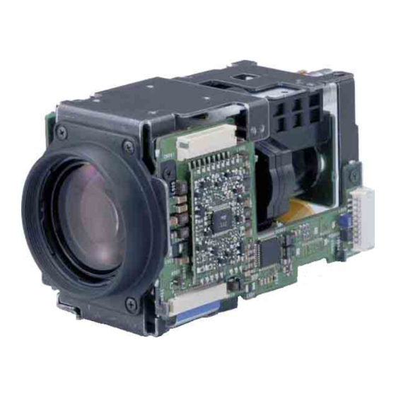
Locations of Controls Locations of Controls Main Unit Front Left side Bottom Right side 1 Lens 5 WIDE button 2 CN901 connector 6 CN601 connector 3 CN903 connector 7 Tripod screw holes 4 TELE button When a tripod is used, please use 10 mm ( in.) screws to attach it to the camera. -
Page 5: Basic Functions
Basic Functions Basic Functions General Overview of Functions • Power On/Off Powers the camera on and off. When the power is off, VISCA commands are the basis of camera control. the camera is able to accept only the lowest level of VISCA Commands;... - Page 6 Basic Functions The AutoFocus (AF) function automatically adjusts Zoom the focus position to maximize the high frequency The FCB camera employs an 18× optical zoom lens content of the picture in a center measurement area, combined with a digital zoom function allowing you to taking into consideration the high luminance and zoom up to 72×.
-
Page 7: White Balance
Basic Functions AE – Shutter Priority White Balance The shutter speed can be set freely by the user to a White Balance has the following modes, all of which total of 22 steps – 16 high speeds and 6 low speeds. can be set using VISCA Commands. - Page 8 Basic Functions AE – Manual When switching from the Shutter Priority mode to the The shutter speed (22 steps), iris (18 steps) and gain Bright mode, the shutter speed set in the Shutter (16 steps) can be set freely by the user. Priority mode is maintained.
-
Page 9: Exposure Compensation
Basic Functions Exposure Compensation Camera ID Exposure compensation is a function which offsets the The ID can be set up to 65,536 (0000 to FFFF). As this internal reference brightness level used in the AE will be memorized in the nonvolatile memory inside mode by steps of 1.5 dB. -
Page 10: Title Display
Basic Functions Memory (Position Preset) Title Display Using the position preset function, 6 sets of camera shooting conditions can be stored and recalled. The camera can be given a title containing up to 20 This function allows you to achieve the desired status characters such as “ENTRANCE”... - Page 11 Basic Functions Privacy Zone Function Features • Mask can be set on up to 24 places according to Pan/ Privacy Zone masking protects private objects and Tilt positions. areas such as house windows, entrances, and exits • Mask can be displayed on 8 places per screen which are within the camera’s range of vision but not simultaneously.
- Page 12 Basic Functions Privacy Zone Setting Command List Command Set Command Command Packet Comments CAM_PrivacyZone SetMask Setting Mask(Size) 8x 01 04 76 mm nn See “mm: mask setting list”, “nn: setting”, and 0r 0r 0s 0s FF “rr: w, ss: h” in “Parameters” on page 13. Display Setting Mask Display On/Off 8x 01 04 77 pp pp pp pp FF...
- Page 13 Basic Functions Parameters mm: Mask setting list nn: Setting Mask Name mm (Hex) Mask Name mm (Hex) Setting Mask_A Mask_M Resetting the zone size (the value of w, h) for the existing mask. Mask_B Mask_N Setting newly the zone size (the value of Mask_C Mask_O w, h).
-
Page 14: Details Of Setting Commands
Basic Functions Comments: Two different color masks can be Details of Setting Commands chosen. Set Mask The colors can be chosen from among 14 colors Command: 8x 01 04 76 mm nn 0r 0r 0s 0s FF including the possibility for semi-transparency of Parameters: each color. - Page 15 Basic Functions Alarm Function Grid Use the grid displayed on the screen to set mask This function instructs the camera to detect movement positions (see the figure below). within the monitoring area and then send an alarm signal automatically. 14hex (20(10)) A High level signal is output when camera detects movement inside the monitoring area.
- Page 16 Basic Functions ALARM Setting Command List Command Set Command Command Packet Comments CAM _ Alarm 8x 01 04 6B 02 FF Alarm start 8x 01 04 6B 03 FF Alarm stop Set Mode 8x 01 04 6C pp FF Mode Setting *Select one from 13 modes Set Day Night Level 8x 01 04 6D 0p 0p 0p...
- Page 17 Basic Functions Flowchart of 12 Modes Function Mode “00” Set the Focus Position Set to the factory preset Hysteresis. Alarm On Focus Position into memory AE moves Focus moves outside of the hysteresis. High level signal output * Repeat this loop until Alarm off. Focus goes back to the previous position.
- Page 18 Basic Functions Mode “01” Focus Position into memory Alarm On Hysteresis is set to the factory preset. AE moves. Focus moves outside of the hysteresis. High level signal output * Repeat this loop until Alarm off. AE does not move for AE does not move for a period of time.
- Page 19 Basic Functions Mode “02” Set to the factory preset Set the AE level Hysteresis. AE Level into memory Alarm On AE moves AE moves outside of the hysteresis. High level signal output * Repeat this loop until Alarm off. AE goes back to the previous level.
- Page 20 Basic Functions Mode “03” AE level into memory Alarm On Hysteresis is set to the factory preset. AE moves. AE moves outside of the hysteresis. High level signal output * Repeat this loop until Alarm off. AE does not move for AE does not move for a period of time.
- Page 21 Basic Functions Details of Mode “01”/“03” T1: Reset interval timer (5sec) T2: Detect timer (2sec) T3: High level signal count timer (2sec) Alarm ON Hysteresis Reset Focus Pos AE Level Reset Reset Reset High Signal level...
- Page 22 Basic Functions Mode “04” High output result of mode “00” High output result of mode “02” High output Low output Mode “05” High output result of mode “00” High output result of mode “03” High output Low output...
- Page 23 Basic Functions Mode “06” High output result of mode “01” High output result of mode “02” Low output High output Mode “07” High output result of mode “01” High output result of mode “03” High output Low output...
- Page 24 Basic Functions Mode “08” High output result of mode “00” High output result of mode “02” High output result of mode “02” High output High output High output Low output Mode “09” High output result of mode “00” High output result of mode “03” High output result of mode “03”...
- Page 25 Basic Functions Mode “0A” High output result of mode “01” High output result of mode “02” High output result of mode “02” High output High output High output Low output Mode “0B” High output result of mode “01” High output result of mode “03” High output result of mode “03”...
- Page 26 Basic Functions Day-Night Mode (Mode “0C”) Set the Day-Night Mode and the Day/ Setting by the VISCA Cmd. Night AE level. Starting distinction between Day Alarm On and Night. AE move Brightness is higher than Day AE level Brightness is higher than Night AE level Low level signal output Low level signal output...
-
Page 27: Eclipse
Basic Functions Eclipse Vibration Specifications When designing the housing, refer to the dimensional allowance as shown in the figure below. Test Method (Random vibration) • Fix the camera at the four fixation points of the base using M2 screws. • Perform the random vibration test under the following conditions in the X, Y and Z directions for 20 minutes in each direction. -
Page 28: Key Switch Circuitry
Basic Functions Key Switch Circuitry... -
Page 29: Key Function Specifications
Basic Functions Key Function Specifications Classification Name Function Button operation Mode display ZOOM WIDE Move ZOOM to WIDE side quickly. Pressing repeatedly allowed. ZOOM bar displayed for 3 s. WIDE SLOW Move ZOOM to WIDE side slowly. Pressing repeatedly allowed. ZOOM bar displayed for 3 s. - Page 30 Basic Functions Classification Name Function Button operation Mode display FEATURE FREEZE Capture still image. Switch on/off. FREEZE indication Horizontal reversal Switch on/off. Horizontal reversal REVERSE indication BLACK & Black-and-white output Switch on/off. B&W display WHITE NEGA ART Negative art output Switch on/off.
-
Page 31: Initial Settings, Custom Preset And Backup
Basic Functions Initial Settings, Custom Preset and Backup Initial settings for the various functions of the FCB camera are indicated in the “Initial settings” column. The “Custom preset” column indicates whether the custom preset function can be used to store the settings. - Page 32 Basic Functions Custom Standby Mode/Position Initial settings preset backup Title Display On/Off Title Setting — Mask Setting — Mask Display On/Off Mask Color Setting — Alarm On/Off Alarm Mode — Alarm Detect Level — E-Flip On/Off Privacy Zone On/Off Privacy Zone Setting —...
-
Page 33: Mode Condition
Basic Functions... - Page 34 Basic Functions...
- Page 35 Basic Functions...
-
Page 36: Command List
SOFTWARE) AND SPECIFICALLY DISCLAIMS network. ANY LIABILITY FOR ANY SUCH MALFUNCTION OR DAMAGE. THIS CONTROL PROTOCOL AND COMMAND LIST SHOULD BE USED WITH CAUTION..............................................1)VISCA is a protocol which controls consumer camcorders developed by Sony. “VISCA” is a trademark of Sony Corporation. -
Page 37: Visca Communication Specifications
Command List Notes VISCA Controller VISCA Equipment • Connect the serial output from the PC to the serial input of camera 1, then connect the serial output of camera 1 to the serial input of camera 2, the serial output of camera 2 to the serial input of camera 3, and the serial output of camera 3 to the serial input of the PC. - Page 38 Command List Command and Inquiry Socket Number ● Command When command messages are sent to the FCB camara, Sends operational commands to the FCB camera. it is normal to send the next command message after ● Inquiry waiting for the completion message or error message Used for inquiring about the current state of the to return.
-
Page 39: Visca Device Setting Command
Inquiry Packet Reply Packet Description command using the broadcast function. IF_DeviceTypeInq 8X 09 00 02 FF Y0 50 GG GG HH GGGG = Vender ID HH JJ JJ KK FF (0020: Sony) HHHH = Model ID For VISCA Network Administration 043C=FCB-IX47C 043D=FCB-IX47CP ●... - Page 40 Command List VISCA Command/ACK Protocol Command Command Message Reply Message Comments General Command 81 01 04 38 02 FF 90 41 FF (ACK)+90 51 FF Returns ACK when a command has been accepted, and (Example) (Completion) Completion when a command has been executed. 90 42 FF 90 52 FF 81 01 04 38 FF...
-
Page 41: Error Messages
Command List VISCA Camera-Issued Messages ACK/Completion Messages Comments Command Messages z0 4y FF Returned when the command is accepted. (y:Socket No.) Completion z0 5y FF Returned when the command has been executed. (y:Socket No.) z = Device address + 8 Error Messages Comments Command Messages... -
Page 42: Fcb Camera Commands
Command List FCB Camera Commands Command List (1/4) Command Set Command Command Packet Comments AddressSet Broadcast 88 30 01 FF IF_Clear Broadcast 88 01 00 01 FF CommandCancel 8x 2p FF p: Socket No.(=1or2) CAM_Power 8x 01 04 00 02 FF Power ON/OFF 8x 01 04 00 03 FF CAM_Zoom... - Page 43 Command List Command List (2/4) Command Set Command Command Packet Comments CAM_WB Auto 8x 01 04 35 00 FF Normal Auto Indoor 8x 01 04 35 01 FF Indoor mode Outdoor 8x 01 04 35 02 FF Outdoor mode One Push WB 8x 01 04 35 03 FF One Push WB mode 8x 01 04 35 04 FF...
- Page 44 Command List Command List (3/4) Command Set Command Command Packet Comments CAM_Aperture Reset 8x 01 04 02 00 FF Aperture Control 8x 01 04 02 02 FF Down 8x 01 04 02 03 FF Direct 8x 01 04 42 00 00 0p 0q FF pq: Aperture Gain CAM_LR_Reverse 8x 01 04 61 02 FF...
- Page 45 Command List Command List (4/4) Command Set Command Command Packet Comments CAM_Mute 8x 01 04 75 02 FF Mute ON/OFF 8x 01 04 75 03 FF On/Off 8x 01 04 75 10 FF CAM_KEY Lock 8x 01 04 17 00 FF Camera control on/off 8x 01 04 17 02 FF CA_ID Write...
- Page 46 Command List Inquiry Command List (1/2) Inquiry Command Command Packet Inquiry Packet Comments CAM_PowerInq 8x 09 04 00 FF y0 50 02 FF y0 50 03 FF CAM_ZoomPosInq 8x 09 04 47 FF y0 50 0p 0q 0r 0s FF pqrs: Zoom Position CAM_DZoomModeInq 8x 09 04 06 FF...
- Page 47 Command List Inquiry Command List (1/2) Inquiry Command Command Packet Inquiry Packet Comments CAM_LR_ReverseModeInq 8x 09 04 61 FF y0 50 02 FF y0 50 03 FF CAM_FreezeModeInq 8x 09 04 62 FF y0 50 02 FF y0 50 03 FF CAM_PictureEffectModeInq 8x 09 04 63 FF y0 50 00 FF...
- Page 48 Command List Block Inquiry Command List Lens Control System Inquiry Commands ....Command Packet 8x 09 7E 7E 00 FF Byte Comments Byte Comments Byte Comments Destination Address Focus Near Limit (H) Source Address 0 Completion Message (50h) DZoomMode 0: Combine 1: Separate 0: Normal 1: Interval 2: Zoom Trigger...
- Page 49 Command List Camera Control System Inquiry Commands ..Command Packet 8x 09 7E 7E 01 FF Byte Comments Byte Comments Byte Comments Destination Address Gain Position Source Address WB Mode 0 Completion Message (50h) Bright Position Aperture Gain Exposure Mode Exposure Comp.
- Page 50 Command List Other Inquiry Commands ........Command Packet 8x 09 7E 7E 02 FF Byte Comments Byte Comments Byte Comments Destination Address External Lock 1: Provided 0: Not provided Memory 1: Provided 0: Not provided Source Address Clock 1: Provided 0: Not provided ICR 1: Provided 0: Not 0 Completion Message (50h)
- Page 51 Command List Enlargement Function Query Command ....Command Packet 8x 09 7E 7E 03 FF Byte Comments Byte Comments Byte Comments Destination Address Advanced Privacy (1: Source Address AF Interval Time (H) Provided, 0: Not provided) Alarm (1: Provided, 0: Not provided) 0 Completion Message (50h) Picture flip (1: Provided, 0:...
-
Page 52: Visca Command Setting Values
Command List VISCA Command Setting Values Exposure Control (1/2) Gain 28 dB 26 dB NTSC 24 dB Shutter Speed 10000 10000 22 dB 20 dB 6000 6000 4000 3500 18 dB 3000 2500 16 dB 2000 1750 14 dB 1500 1250 12 dB 1000... - Page 53 Command List Exposure Control (2/2) Zoom Ratio and Zoom Position (for reference) IRIS GAIN Bright F1.4 28 dB Zoom Ratio Optical Zoom ×18 Lens Position Data F1.4 26 dB F1.4 24 dB ×1 0000 F1.4 22 dB ×2 1606 F1.4 20 dB ×3 2151...
-
Page 54: Title Setting
Command List Lens Control 0000 4000 7000 Zoom Position Wide end Optical Tele end Digital Tele end 1000 C000 Focus Position Far end Near end 1000: Over Inf 2000: 8.0 m & 3000: 3.5 m 4000: 2.0 m As the distance on the left 5000: 1.4 m will differ due to temperature 6000: 1 m... -
Page 55: Specifications
Specifications Specifications Image sensor type Super HAD CCD White balance AUTO, ATW, Indoor, Outdoor, Picture elements FCB-IX47C/IX45C: Approx. 380K One Push WB, Manual WB pixels (768 (H) × 494 (V)) Gain Auto/Manual (–3 to 28 dB, 2 dB FCB-IX47CP/IX45CP: Approx. steps) 440K pixels (752 (H) ×... - Page 56 Specifications Dimensions Front Right side 48.2 (1 92.3 (3 4.1 ( (24.2( 24 ( 9.6 ( 39.3 (1 M37 p0.75 ( 3.6 ( 9.6 ( 31.4 ( Left side 7–M2 20±0.1 ( 19.1 ( Within a depth of 3 mm ( in.) or less from the top surface Bottom...
- Page 57 Specifications Pin assignment CN901 CN601 q;987654321 qsqaq;987654321 CN901 (for communications) CN601 (for FFC cable) Pin No. Name Level Pin No. Name Level TxD IN RS-232C level KEY_AD0 RxD IN RS-232C level KEY_AD1 TTL level KEY_AD2 KEY_AD3 KEY_AD4 TTL level KEY_AD5 KEY_AD6 KEY_AD7 Connector type: JST S10B-ZR-SM3A-TF...
-
Page 58: Precautions
Sony Corporation is not liable for any damages under these In case of abnormal operation, contact your authorized conditions. Sony dealer or the store where you purchased the product. Operation Start the camera control software on your computer after you turn on the camera and the image is displayed. - Page 59 Precautions Differences Among FCB-IX47C/IX47CP and FCB-IX45C/IX45CP The main differences among the FCB-IX47C/IX47CP and FCB-IX45C/IX45CP are as follows. Function/Item FCB-IX47C/IX47CP FCB-IX45C/IX45CP Slow shutter E-FLIP function Packing Individual packing carton Master carton with 10 units packed...