Table of Contents
Advertisement
Quick Links
Intel
D850MD/D850MV
Technical Product Specification
®
The Intel
Desktop Boards D850MD/D850MV may contain design defects or errors known as errata that may cause the product to deviate from published specifications. Current
characterized errata are documented in the Intel Desktop Board D850MD/D850MV Specification Update.
®
Desktop Board
August 2001
Order Number: A65145-001
Advertisement
Table of Contents

Related Manuals for Intel D850MVSE


Summary of Contents for Intel D850MVSE
- Page 1 Order Number: A65145-001 ® The Intel Desktop Boards D850MD/D850MV may contain design defects or errors known as errata that may cause the product to deviate from published specifications. Current characterized errata are documented in the Intel Desktop Board D850MD/D850MV Specification Update.
-
Page 2: Revision History
Intel products are not intended for use in medical, life saving, or life sustaining applications or for any other application in which the failure of the Intel product could create a situation where personal injury or death may occur. -
Page 3: Intended Audience
Preface This Technical Product Specification (TPS) specifies the board layout, components, connectors, ® power and environmental requirements, and the BIOS for these Intel Desktop Boards: D850MD and D850MV. It describes the standard product and available manufacturing options. Intended Audience The TPS is intended to provide detailed, technical information about the D850MD and D850MV boards and their components to the vendors, system integrators, and other engineers and technicians who need this level of information. - Page 4 Intel Desktop Board D850MD/D850MV Technical Product Specification Other Common Notation Used after a signal name to identify an active-low signal (such as USB#) When used in the description of a component, N indicates the component type, xn are the (NxnX) relative coordinates of its location on the D850MD and D850MV boards, and X is the instance of the particular part at that general location.
-
Page 5: Table Of Contents
Design Specifications ....................19 Processor ........................22 System Memory ......................23 1.7.1 Memory Features ..................23 1.7.2 Continuity RIMM Modules ................23 1.7.3 RDRAM Memory Configuration ..............24 ® Intel 850 Chipset.......................25 1.8.1 AGP ......................26 1.8.2 USB......................27 1.8.3 IDE Support ....................29 1.8.4 Real-Time Clock, CMOS SRAM, and Battery..........30 ®... - Page 6 Intel Desktop Board D850MD/D850MV Technical Product Specification 2 Technical Reference Introduction.........................47 Memory Map ......................47 I/O Map ........................48 DMA Channels ......................50 PCI Configuration Space Map ..................50 Interrupts ........................51 PCI Interrupt Routing Map ..................51 Connectors .........................53 2.8.1 Back Panel Connectors................54 2.8.2 Internal I/O Connectors ................57 2.8.3...
- Page 7 Contents ® Fast Booting Systems with Intel Rapid BIOS Boot ............92 3.9.1 Peripheral Selection and Configuration ............92 3.9.2 Intel Rapid BIOS Boot ..................93 3.9.3 Operating System ..................93 3.10 BIOS Security Features....................94 4 BIOS Setup Program Introduction.........................95 Maintenance Menu .....................96 4.2.1 Extended Configuration Submenu..............97...
- Page 8 Intel Desktop Board D850MD/D850MV Technical Product Specification Location of the Standby Power Indicator LED ............45 Back Panel Connectors ....................54 Audio Connectors .......................58 Power and Hardware Control Connectors ..............60 Add-in Board and Peripheral Interface Connectors (D850MD Board) ......63 Add-in Board and Peripheral Interface Connectors (D850MV Board) ......64 External I/O Connectors .....................70...
- Page 9 Contents Main Power Connector ....................62 Optional Auxiliary Power Connector (Required for AGP Pro Only) ......62 Fan 2 Connector......................62 CNR Connector (Optional)..................65 PCI Bus Connectors ....................66 AGP Connector ......................67 Diskette Drive Connector....................68 IDE Connectors ......................69 SCSI Hard Drive Activity LED Connector..............69 Front Panel Audio Connector ..................71 Front Panel USB Connector ..................71 Auxiliary Front Panel Power/Sleep/Message-Waiting LED Connector ......71...
- Page 10 Intel Desktop Board D850MD/D850MV Technical Product Specification Exit Menu .........................116 BIOS Error Messages....................117 Uncompressed INIT Code Checkpoints..............119 Boot Block Recovery Code Checkpoints ..............119 Run-Time Code Uncompressed in F000 Shadow RAM ..........120 Bus Initialization Checkpoints ...................123 Upper Nibble High Byte Functions................123 Lower Nibble High Byte Functions................124...
-
Page 11: Product Description
1.13 Hardware Management Subsystem................37 1.14 Power Management ....................38 1.1 Board Differences ® This TPS describes these Intel desktop boards: D850MD and D850MV. The boards are identical except for the differences listed in Table 1 below. Table 1. Summary of Board Differences D850MD microATX form factor (9.60 inches by 9.60 inches) -
Page 12: Overview
D850MV: Five PCI bus add-in card connectors (SMBus routed to PCI bus connector 2) BIOS Intel/AMI BIOS (resident in the Intel 82802AB 4 Mbit FWH) Support for Advanced Power Management (APM), Advanced Configuration and Power Interface (ACPI), Plug and Play, and System Management BIOS... -
Page 13: Manufacturing Options
Section 1.5, page 19 1.2.2 Manufacturing Options Table 3 describes the D850MD and D850MV boards’ manufacturing options. Not every manufacturing option is available in all marketing channels. Please contact your Intel representative to determine which manufacturing options are available to you. Table 3. -
Page 14: Board Layouts
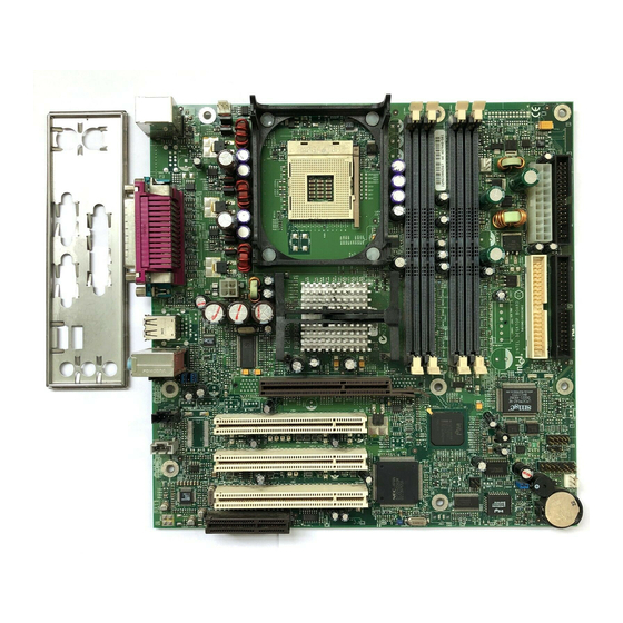
Intel Desktop Board D850MD/D850MV Technical Product Specification 1.2.3 Board Layouts Figure 1 shows the location of the major components on the D850MD board. OM12320 AD1885 audio codec Diskette drive connector Intel 82562ET PLC device (optional) IDE connectors AGP connector Auxiliary power connector (optional) -
Page 15: D850Mv Board Components
Product Description Figure 2 shows the location of the major components on the D850MV board. OM12321 AD1885 audio codec IDE connectors Intel 82562ET PLC device (optional) Auxiliary power connector (optional) AGP connector SMSC LPC47M142 I/O controller (AGP Pro50 connector optional) -
Page 16: Block Diagram
Intel Desktop Board D850MD/D850MV Technical Product Specification 1.2.4 Block Diagram Figure 3 is a block diagram of the major functional areas of the standard D850MD and D850MV boards. See Figure 7 on page 27 for USB port routing. Diskette Drive... -
Page 17: Block Diagram With Optional Usb 2.0 Support
Product Description Figure 4 is a block diagram of the major functional areas of D850MD and D850MV boards with the USB 2.0 manufacturing option. See Figure 8 on page 28 for USB port routing. Diskette Drive Primary/ Connector ATA-66/100 Secondary IDE Serial Ports Parallel Port Controller... -
Page 18: Online Support
Intel Desktop Board D850MD/D850MV Technical Product Specification 1.3 Online Support To find information about… Visit this World Wide Web site: Intel’s D850MD and D850MV boards http://www.intel.com/design/motherbd http://support.intel.com/support/motherboards/desktop Processor data sheets http://www.intel.com/design/litcentr ICH2 addressing http://developer.intel.com/design/chipsets/datashts Custom splash screens http://intel.com/design/motherbd/gen_indx.htm Audio software and utilities http://www.intel.com/design/motherbd... -
Page 19: Design Specifications
BIOS Specification 1999, bios.platforms.desktop.html American Megatrends, Inc. Advanced Power Version 1.2, http://www.microsoft.com/ Management BIOS February 1996, hwdev/busbios/amp_12.htm Interface Intel Corporation and Specification Microsoft Corporation. ATA/ Information Revision 3, http://www.t13.org ATAPI-5 Technology - AT February 29, 2000, Attachment with Contact: T13 Chair, Packet Interface - 5, Seagate Technology. - Page 20 Intel Desktop Board D850MD/D850MV Technical Product Specification Table 4. Specifications (continued) Reference Specification Version, Revision Date and The information is available Name Title Ownership from… IEEE std 1284.1-1997 Version 1.7, http://standards.ieee.org/ Enhanced Parallel Port 1997, reading/ieee/std_public/ Institute of Electrical and description/busarch/ Electronic Engineers.
- Page 21 BIOS March 16, 1999, standards/bios.php American Megatrends Inc., Award Software International Inc., Compaq Computer Corporation, Dell Computer Corporation, Hewlett-Packard Company, Intel Corporation, International Business Machines Corporation, Phoenix Technologies Limited, and SystemSoft Corporation. UHCI Universal Host Version 1.1, http://www.usb.org/ Controller Interface March 1996, developers/docs.html...
-
Page 22: Processor
Intel Pentium 4 processor and the Intel 850 chipset. Always connect the 20-pin and 4-pin leads of the ATX12V power supply to the corresponding connectors on the D850MD and D850MV boards. -
Page 23: System Memory
Product Description 1.7 System Memory CAUTION Turn off the power and unplug the power cord before installing or removing RIMM modules. Failure to do so could damage the memory and the board. (After AC power is removed, the standby power indicator LED should not be lit. See Figure 11 on page 45 for the location of the standby power indicator LED.) NOTE The board supports combinations of no more than 32 RDRAM components per RDRAM bank. -
Page 24: Rdram Memory Configuration
Intel Desktop Board D850MD/D850MV Technical Product Specification 1.7.3 RDRAM Memory Configuration When installing memory, note the following: The four RIMM sockets are grouped into two banks: Bank 0 (labeled on the board as RIMM1 and RIMM2) Bank 1 (labeled on the board as RIMM3 and RIMM4) Bank 0 must be populated first, ensuring that the RDRAM installed in RIMM1 and RIMM2 is identical in speed, size, and density. -
Page 25: Intel ® 850 Chipset
Product Description 1.8 Intel ® 850 Chipset The Intel 850 chipset consists of the following devices: Intel 82850 MCH with Accelerated Hub Architecture (AHA) bus Intel 82801BA ICH2 with AHA bus Intel 82802AB FWH The MCH is a centralized controller for the system bus, the memory bus, the AGP bus, and the AHA interface. -
Page 26: Agp
Intel Desktop Board D850MD/D850MV Technical Product Specification 1.8.1 AGP NOTE The AGP connector is keyed for 1.5 V AGP cards only. Do not attempt to install a legacy 3.3 V AGP card. The AGP connector is not mechanically compatible with legacy 3.3 V AGP cards. See Figure 6 for more information on the AGP keying mechanism. -
Page 27: Usb
Product Description 1.8.2 USB The following sections describe the USB port configurations implemented on the D850MD/D850MV boards. NOTE Computer systems that have an unshielded cable attached to a USB port may not meet FCC Class B requirements, even if no device is attached to the cable. Use shielded cable that meets the requirements for full-speed devices. -
Page 28: Usb 2.0 Port Configuration (Optional)
Intel Desktop Board D850MD/D850MV Technical Product Specification 1.8.2.2 USB 2.0 Support (Optional) NOTE The USB 2.0 option is currently available only on the D850MV board. The D850MV board supports USB 2.0 using the NEC PD720100 USB 2.0 host controller, which is a manufacturing option. -
Page 29: Ide Support
Product Description 1.8.3 IDE Support 1.8.3.1 IDE Interfaces The ICH2’s IDE controller has two independent bus-mastering IDE interfaces that can be independently enabled. The IDE interfaces support the modes listed in Table 7. Table 7. Supported IDE Modes Mode Description Supported Transfer Rates Programmed I/O Processor controls data transfer... -
Page 30: Real-Time Clock, Cmos Sram, And Battery
Intel Desktop Board D850MD/D850MV Technical Product Specification 1.8.3.2 SCSI Hard Drive Activity LED Connector The SCSI hard drive activity LED connector is a 1 x 2–pin connector that allows an add-in SCSI controller to use the same LED as the onboard IDE controller. For proper operation, this connector should be wired to the LED output of the add-in SCSI controller. -
Page 31: I/O Controller
Product Description 1.9 I/O Controller The SMSC LPC47M142 I/O controller provides the following features: 3.3 V operation Two serial ports One parallel port with Extended Capabilities Port (ECP) and Enhanced Parallel Port (EPP) support Serial IRQ interface compatible with serialized IRQ support for PCI systems PS/2-style mouse and keyboard interfaces Interface for one 1.2 MB or 1.44 MB diskette drive Intelligent power management, including a programmable wake-up event interface... -
Page 32: Parallel Port
Intel Desktop Board D850MD/D850MV Technical Product Specification 1.9.2 Parallel Port The 25-pin D-Sub parallel port connector is located on the back panel. In the BIOS Setup program, the parallel port can be set to the following modes: † Output only (PC-AT –compatible mode) -
Page 33: Audio Subsystem
Back panel audio connectors: Line out Line in Mic in The audio subsystem consists of the following devices: Intel 82801BA ICH2 Analog Devices AD1885 analog codec Figure 9 is a block diagram of the audio subsystem. Line In Line Out 82801BA AC ’97... -
Page 34: Audio Connectors
Figure 13, page 58 The signal names of the ATAPI CD-ROM connector Table 28, page 59 1.10.2 Audio Subsystem Software Audio software and drivers are available from Intel’s World Wide Web site. For information about Refer to Obtaining audio software and drivers... -
Page 35: Lan Subsystem (Optional)
® 1.11.1 Intel 82562ET PLC Device The Intel 82562ET component provides an interface to the back panel RJ-45 connector with integrated LEDs. This physical interface may alternately be provided through the CNR connector. The Intel 82562ET provides the following functions:... -
Page 36: Lan Subsystem Software
Section 1.3, page 18 1.12 CNR (Optional) The CNR connector provides an interface that supports the audio, modem, USB, and LAN interfaces of the Intel 850 chipset. Figure 10 shows the signal interface between the riser and the ICH2. AC ’97 Interface... -
Page 37: Hardware Management Subsystem
Product Description 1.13 Hardware Management Subsystem The hardware management features enable the boards to be compatible with the Wired for Management (WfM) specification. The board has several hardware management features, including the following: Fan control and monitoring Thermal and voltage monitoring For information about Refer to The WfM specification... -
Page 38: Power Management
Intel Desktop Board D850MD/D850MV Technical Product Specification 1.14 Power Management Power management is implemented at several levels, including: Software support: ACPI Hardware support: Power connector Fan connectors LAN wake capabilities Instantly Available technology Wake from USB Wake from PS/2 keyboard PME# wake-up support 1.14.1 Software Support... -
Page 39: Effects Of Pressing The Power Switch
Product Description 1.14.1.2 ACPI ACPI gives the operating system direct control over the power management and Plug and Play functions of a computer. The use of ACPI with the D850MD and D850MV boards requires an operating system that provides full ACPI support. ACPI features include: Plug and Play (including bus and device enumeration) and APM support (normally contained in the BIOS). -
Page 40: Power States And Targeted System Power
Intel Desktop Board D850MD/D850MV Technical Product Specification 1.14.1.2.1 System States and Power States Under ACPI, the operating system directs all system and device power state transitions. The operating system puts devices in and out of low-power states based on user preferences and knowledge of how devices are being used by applications. -
Page 41: Wake-Up Devices And Events
Product Description 1.14.1.2.2 Wake-up Devices and Events Table 11 lists the devices or specific events that can wake the computer from specific states. Table 11. Wake-up Devices and Events These devices/events can wake up the computer… …from this state Power switch S1, S3, S4, S5 RTC alarm S1, S3, S4, S5... -
Page 42: Hardware Support
Intel Desktop Board D850MD/D850MV Technical Product Specification 1.14.2 Hardware Support CAUTION Ensure that the power supply provides adequate +5 V standby current if the LAN wake capabilities and Instantly Available technology features are used. Failure to do so can damage the power supply. -
Page 43: Fan Connector Descriptions
Product Description 1.14.2.2 Fan Connectors The D850MD and D850MV boards have two fan connectors with thermal control signals (fan 1 and fan 2) that are used to switch the fans on and off as determined by the thermal sensors. The ambient temperature of a D850MD- or D850MV-based system is thermally monitored by separate temperature sensors that control voltage to the fan 1 and fan 2 connectors. - Page 44 Intel Desktop Board D850MD/D850MV Technical Product Specification 1.14.2.3 LAN Wake Capabilities CAUTION For LAN wake capabilities, the +5 V standby line for the power supply must be capable of providing adequate +5 V standby current. Failure to provide adequate standby current when implementing LAN wake capabilities can damage the power supply.
-
Page 45: Location Of The Standby Power Indicator Led
Product Description The standby power indicator LED shows that power is still present at the RIMM, PCI bus, AGP, and CNR connectors, even when the computer appears to be off. Figure 11 shows the location of the standby power indicator LED. CR7F1 OM12322 Figure 11. - Page 46 Intel Desktop Board D850MD/D850MV Technical Product Specification...
-
Page 47: Technical Reference
2 Technical Reference What This Chapter Contains Introduction.........................47 Memory Map ......................47 I/O Map ........................48 DMA Channels ......................50 PCI Configuration Space Map ..................50 Interrupts ........................51 PCI Interrupt Routing Map ..................51 Connectors .........................53 Jumper Block......................74 2.10 Mechanical Considerations..................76 2.11 Electrical Considerations ....................79 2.12 Thermal Considerations....................82 2.13 Reliability ........................83 2.14 Environmental ......................84... -
Page 48: I/O Map
Intel Desktop Board D850MD/D850MV Technical Product Specification 2.3 I/O Map Table 14. I/O Map Address (hex) Size Description 0000 - 000F 16 bytes DMA controller 0020 - 0021 2 bytes Programmable Interrupt Control (PIC) 0040 - 0043 4 bytes System timer... - Page 49 16 contiguous bytes starting on a 16-byte ICH2 (SMBus) divisible boundary 4096 contiguous bytes starting on a 4096-byte Intel 82801BA PCI bridge divisible boundary 256 contiguous bytes starting on a 256-byte ICH2 audio mixer divisible boundary 64 contiguous bytes starting on a 64-byte...
-
Page 50: Dma Channels
Intel Desktop Board D850MD/D850MV Technical Product Specification 2.4 DMA Channels Table 15. DMA Channels DMA Channel Number Data Width System Resource 8 or 16 bits Open 8 or 16 bits Parallel port 8 or 16 bits Diskette drive 8 or 16 bits... -
Page 51: Interrupts
Technical Reference 2.6 Interrupts Table 17. Interrupts System Resource I/O channel check Reserved, interval timer Reserved, keyboard buffer full Reserved, cascade interrupt from slave PIC (Note) COM2 (Note) COM1 LPT2 (Plug and Play option) / Audio / User available Diskette drive (Note) LPT1 Real-time clock... -
Page 52: Pci Interrupt Routing Map
Intel Desktop Board D850MD/D850MV Technical Product Specification The ICH2 has eight programmable interrupt request (PIRQ) input signals. All PCI interrupt sources either onboard or from a PCI add-in card connect to one of these PIRQ signals. Some PCI interrupt sources are electrically tied together on the D850MD and D850MV boards and therefore share the same interrupt. -
Page 53: Connectors
Technical Reference 2.8 Connectors CAUTION Only the back panel connectors and the front panel USB connector of the D850MD and D850MV boards have overcurrent protection. All of the remaining internal connectors on the D850MD and D850MV boards are not overcurrent protected and should connect only to devices inside the computer’s chassis, such as fans and internal peripherals. -
Page 54: Back Panel Connectors
Intel Desktop Board D850MD/D850MV Technical Product Specification 2.8.1 Back Panel Connectors Figure 12 shows the location of the back panel connectors. The back panel connectors are color coded in compliance with PC 99 recommendations. The figure legend below lists the colors used. -
Page 55: Ps/2 Mouse/Keyboard Connectors
Technical Reference Table 19. PS/2 Mouse/Keyboard Connectors Signal Name Data Not connected Ground +5 V Clock Not connected Table 20. USB Connectors Signal Name +5 V USB# Ground Table 21. Parallel Port Connector Standard Signal Name ECP Signal Name EPP Signal Name STROBE# STROBE# WRITE#... -
Page 56: Serial Port Connectors
Intel Desktop Board D850MD/D850MV Technical Product Specification Table 22. Serial Port Connectors Signal Name DCD (Data Carrier Detect) RXD# (Receive Data) TXD# (Transmit Data) DTR (Data Terminal Ready) Ground DSR (Data Set Ready) RTS (Request to Send) CTS (Clear to Send) RI (Ring Indicator) Table 23. -
Page 57: Internal I/O Connectors
Technical Reference 2.8.2 Internal I/O Connectors The internal I/O connectors are divided into the following functional groups: Audio (see page 58) Auxiliary line in ATAPI CD-ROM Power and hardware control (see page 60) Fans (three on the D850 MD board, four on the D850MV board) ATX12V Main power Auxiliary power (optional) -
Page 58: Audio Connectors
Intel Desktop Board D850MD/D850MV Technical Product Specification 2.8.2.2 Audio Connectors Figure 13 shows the location of the audio connectors. OM12324 Item Description Color For more information see: Auxiliary line in, ATAPI style White Table 27, page 59 ATAPI CD-ROM Black Table 28, page 59 Figure 13. -
Page 59: Auxiliary Line In Connector
Technical Reference Table 27. Auxiliary Line In Connector Signal Name Left auxiliary line in Ground Ground Right auxiliary line in Table 28. ATAPI CD-ROM Connector Signal Name Left audio input from CD-ROM CD audio differential ground CD audio differential ground Right audio input from CD-ROM... -
Page 60: Power And Hardware Control Connectors
Intel Desktop Board D850MD/D850MV Technical Product Specification 2.8.2.3 Power and Hardware Control Connectors Figure 14 shows the location of the power and hardware control connectors. NOTE Figure 14 shows the D850MV board. Fan 3 is not present on the D850MD board. -
Page 61: Fan 3 Connector (D850Mv Board Only)
Intel Pentium 4 processor and the Intel 850 chipset. Always connect the 20-pin and 4-pin leads of the ATX12V power supply to the corresponding connectors on the D850MD and D850MV boards. Otherwise, the board and the processor could be damaged. -
Page 62: Main Power Connector
Intel Desktop Board D850MD/D850MV Technical Product Specification Table 34. Main Power Connector Signal Name Signal Name +3.3 V +3.3 V +3.3 V -12 V Ground Ground +5 V PS_ON# (power supply remote on/off) Ground Ground +5 V Ground Ground Ground... -
Page 63: Add-In Board And Peripheral Interface Connectors (D850Md Board)
Technical Reference OM12326 Item Description For more information see: CNR (optional) Table 37, page 65 PCI bus connector 3 Table 38, page 66 PCI bus connector 2 Table 38, page 66 PCI bus connector 1 Table 38, page 66 AGP connector Table 39, page 67 Diskette drive Table 40, page 68... -
Page 64: Add-In Board And Peripheral Interface Connectors (D850Mv Board)
Intel Desktop Board D850MD/D850MV Technical Product Specification OM12327 Item Description For more information see: CNR (optional) Table 37, page 65 PCI bus connector 5 Table 38, page 66 PCI bus connector 4 Table 38, page 66 PCI bus connector 3... -
Page 65: Cnr Connector (Optional)
Technical Reference Table 37. CNR Connector (Optional) Signal Name Signal Name Reserved Reserved Reserved Reserved Ground Reserved Reserved Ground Reserved Reserved Ground Reserved LAN_TXD2 Ground LAN_TXD0 LAN_TXD1 Ground LAN_RSTSYNC LAN_CLK Ground LAN_RXD1 LAN_RXD2 Reserved LAN_RXD0 USB+ Ground Ground Reserved USB- +5 V (dual) +12 V USB_OC... -
Page 66: Pci Bus Connectors
Intel Desktop Board D850MD/D850MV Technical Product Specification Table 38. PCI Bus Connectors Signal Name Signal Name Signal Name Signal Name Ground (TRST#)* -12 V AD16 AD17 +12 V Ground (TCK)* +3.3 V C/BE2# +5 V (TMS)* Ground FRAME# Ground +5 V (TDI)*... -
Page 67: Agp Connector
Technical Reference Table 39. AGP Connector Signal Name Signal Name Signal Name Signal Name +12 V Not connected A34 Vddq Vddq TYPEDET# +5 V AD22 AD21 Reserved +5 V AD20 AD19 Not connected Not connected A37 Ground Ground Ground Ground AD18 AD17 INTA#... -
Page 68: Diskette Drive Connector
Intel Desktop Board D850MD/D850MV Technical Product Specification Table 40. Diskette Drive Connector Signal Name Signal Name Ground DENSEL Ground Reserved FDEDIN Ground FDINDX# (Index) Ground FDM00# (Motor Enable A) Ground Not connected Ground FDDS0# (Drive Select A) Ground Not connected... -
Page 69: Ide Connectors
Technical Reference Table 41. IDE Connectors Signal Name Signal Name Reset IDE Ground Data 7 Data 8 Data 6 Data 9 Data 5 Data 10 Data 4 Data 11 Data 3 Data 12 Data 2 Data 13 Data 1 Data 14 Data 0 Data 15 Ground... -
Page 70: External I/O Connectors
Intel Desktop Board D850MD/D850MV Technical Product Specification 2.8.3 External I/O Connectors Figure 17 shows the locations of the external I/O connectors. OM12328 Item Description For more information see: Front panel audio Table 43, page 71 Front panel USB Table 44, page 71... -
Page 71: Front Panel Audio Connector
Technical Reference Table 43. Front Panel Audio Connector Signal Name Signal Name MIC_IN_FP AUD_JACK_GND MIC_BIAS V_5P0_AUD_ANALOG R_FNTOUT R_RETIN Not connected Not connected L_FNT_OUT L_RETIN Table 44. Front Panel USB Connector Signal Name Signal Name VREG_FP_USB _PWR VREG_FP_USB _PWR ICH_U_P2# ICH_U_P3# ICH_U_P2 ICH_U_P3 Ground... -
Page 72: Front Panel Connector
Intel Desktop Board D850MD/D850MV Technical Product Specification 2.8.3.2 Front Panel Connector This section describes the functions of the front panel connector. Table 46 lists the signal names of the front panel connector. Table 46. Front Panel Connector Signal In/Out Description... -
Page 73: States For A Two-Color Power Led
Technical Reference Table 48. States for a Two-Color Power LED LED State Description Power off Steady Green Running Blinking Green Running/message waiting Steady Yellow Sleeping Blinking Yellow Sleeping/message waiting NOTE To use the message-waiting function, ACPI must be enabled in the operating system and a message-capturing application must be invoked. -
Page 74: Jumper Block
Intel Desktop Board D850MD/D850MV Technical Product Specification 2.9 Jumper Block CAUTION Do not move any jumpers with the power on. Always turn off the power and unplug the power cord from the computer before changing a jumper setting. Otherwise, the board could be damaged. -
Page 75: Bios Setup Configuration Jumper Settings
Technical Reference The 3-pin jumper block determines the BIOS Setup program’s mode. Table 49 describes the jumper settings for the three modes: normal, configure, and recovery. When the jumper is set to configuration mode and the computer is powered up, the BIOS compares the processor version and the microcode version in the BIOS and reports if the two match. -
Page 76: Mechanical Considerations
Intel Desktop Board D850MD/D850MV Technical Product Specification 2.10 Mechanical Considerations 2.10.1 D850MD Form Factor The D850MD board is designed to fit into a microATX form factor chassis. Figure 19 illustrates the mechanical form factor for the D850MD board. Dimensions are given in inches [millimeters]. -
Page 77: D850Mv Form Factor
Technical Reference 2.10.2 D850MV Form Factor The D850MV board is designed to fit into an ATX form factor chassis. Figure 20 illustrates the mechanical form factor for the D850MV board. Dimensions are given in inches [millimeters]. The outer dimensions are 12.00 inches by 9.60 inches [304.48 millimeters by 243.84 millimeters]. Location of the I/O connectors and mounting holes are in compliance with the ATX specification (see Section 1.5). -
Page 78: I/O Shield
Intel Desktop Board D850MD/D850MV Technical Product Specification 2.10.3 I/O Shield The back panel I/O shield for D850MD and D850MV boards must meet specific dimension and material requirements. Systems based on these boards need the back panel I/O shield to pass certification testing. -
Page 79: Electrical Considerations
2.11.1 Power Consumption Table 50 lists voltage and current measurements for a computer that contains the D850MD/D850MV board and the following: 1.7 GHz Intel Pentium 4 processor with a 256 KB cache 128 MB PC800 ECC RDRAM AGP 4X/2X video card 3.5-inch diskette drive... -
Page 80: Standby Current Requirements
Intel Desktop Board D850MD/D850MV Technical Product Specification 2.11.3 Standby Current Requirements CAUTION If the standby current necessary to support multiple wake events from the PCI and/or USB buses exceeds power supply capacity, the D850MD and D850MV boards may lose register settings stored in memory, etc. -
Page 81: Fan Connector Current Capability
Technical Reference NOTE IBM PS/2 Port Specification (September 1991) states: 275 mA for keyboard 70 mA for the mouse (non-wake-enabled device) PCI/AGP requirements are calculated by totaling the following: One wake-enabled device @ 375 mA, plus Five non-wake-enabled devices @ 20 mA each, plus USB requirements are calculated as: One wake-enabled device @ 500 mA USB hub @ 100 mA... -
Page 82: Thermal Considerations
Intel Desktop Board D850MD/D850MV Technical Product Specification 2.12 Thermal Considerations CAUTION Ensure that the ambient temperature does not exceed the board’s maximum operating temperature by more than 10 C. Failure to do so could cause components to exceed their maximum case temperature and malfunction. -
Page 83: Reliability
Intel 82801BA ICH2 C (under bias) For information about Refer to Intel Pentium 4 processor datasheets and specification updates Section 1.3, page 18 2.13 Reliability The mean time between failures (MTBF) prediction is calculated using component and subassembly random failure rates. The calculation is based on the Bellcore Reliability Prediction Procedure, TR-NWT-000332, Issue 4, September 1991. -
Page 84: Environmental
Intel Desktop Board D850MD/D850MV Technical Product Specification 2.14 Environmental Table 53 lists the environmental specifications for the D850MD and D850MV boards. Table 53. D850MD/D850MV Board Environmental Specifications Parameter Specification Temperature Nonoperating -40 C to +70 C Operating 0 C to +55 C... -
Page 85: Regulatory Compliance
Technical Reference 2.15 Regulatory Compliance This section describes the D850MD and D850MV boards’ compliance with U.S. and international safety and electromagnetic compatibility (EMC) regulations. 2.15.1 Safety Regulations Table 54 lists the safety regulations that the D850MD and D850MV boards comply with when correctly installed in a compatible host system. -
Page 86: Product Certification Markings (Board Level)
Consists of lower case c followed by a stylized backward UR and Recognized Component mark followed by a small US Includes the adjacent UL file number for Intel desktop boards — For the D850MD board, the number is E139761. — For the D850MV board, the number is E210882. -
Page 87: Overview Of Bios Features
3.10 BIOS Security Features....................94 3.1 Introduction The D850MD and D850MV boards use an Intel/AMI BIOS that is stored in the FWH and can be updated using a software utility. The FWH contains the BIOS Setup program, POST, APM, the PCI autoconfiguration utility, and Plug and Play support. -
Page 88: Bios Flash Memory Organization
Intel Desktop Board D850MD/D850MV Technical Product Specification 3.2 BIOS Flash Memory Organization The Intel 82802AB FWH includes a 4 Mbit (512 KB) symmetrical flash memory device. Internally, the device is grouped into eight 64 KB blocks that are individually erasable, lockable, and unlockable. -
Page 89: Smbios
Overview of BIOS Features 3.4 SMBIOS SMBIOS is a Desktop Management Interface (DMI)–compliant method for managing computers in a managed network. The main component of SMBIOS is the management information format (MIF) database, which contains information about the computing system and its components. Using SMBIOS, a system administrator can obtain the system types, capabilities, operational status, and installation dates for system components. -
Page 90: Bios Updates
Legacy USB support is for keyboards and mice only. Other USB devices are not supported in legacy mode. 3.6 BIOS Updates The BIOS can be updated using either of the following utilities, which are available on the Intel World Wide Web site: ®... -
Page 91: Custom Splash Screen
During POST, an Intel splash screen is displayed by default. This splash screen can be replaced with a custom splash screen. A utility is available from Intel to assist with creating a custom splash screen. The custom splash screen can be programmed into the flash memory using the BIOS upgrade utility. -
Page 92: Boot Options
Rapid BIOS Boot Three factors affect system boot speed: Selecting and configuring peripherals properly ® Using an optimized BIOS, such as the Intel Rapid BIOS Selecting a compatible operating system 3.9.1 Peripheral Selection and Configuration The following techniques help improve system boot speed: Choose a hard drive with parameters such as “power-up to data ready”... -
Page 93: Intel Rapid Bios Boot
It is possible to optimize the boot process to the point where the system boots so quickly that the Intel logo screen (or a custom logo splash screen) will not be seen. Monitors and hard disk drives with minimum initialization times can also contribute to a boot time that might be so fast that necessary logo screens and POST messages cannot be seen. -
Page 94: Bios Security Features
Intel Desktop Board D850MD/D850MV Technical Product Specification 3.10 BIOS Security Features The BIOS includes security features that restrict access to the BIOS Setup program and who can boot the computer. A supervisor password and a user password can be set for the BIOS Setup... -
Page 95: Bios Setup Program
4 BIOS Setup Program What This Chapter Contains Introduction.........................95 Maintenance Menu .....................96 Main Menu........................98 Advanced Menu......................99 Security Menu ......................110 Power Menu ......................111 Boot Menu ........................113 Exit Menu .........................116 4.1 Introduction The BIOS Setup program can be used to view and change the BIOS settings for the computer. The BIOS Setup program is accessed by pressing the <F2>... -
Page 96: Maintenance Menu
Intel Desktop Board D850MD/D850MV Technical Product Specification Table 60 lists the function keys available for menu screens. Table 60. BIOS Setup Program Function Keys BIOS Setup Program Function Key Description < > or < > Selects a different menu screen (Moves the cursor left or right) <... -
Page 97: Extended Configuration Submenu
BIOS Setup Program 4.2.1 Extended Configuration Submenu To access this submenu, select Maintenance on the menu bar and then Extended Configuration. Main Advanced Security Power Boot Exit Maintenance Extended Configuration The submenu represented by Table 62 is for setting video memory cache mode. This submenu becomes available when User Defined is selected under Extended Configuration. -
Page 98: Main Menu
Intel Desktop Board D850MD/D850MV Technical Product Specification 4.3 Main Menu To access this menu, select Main on the menu bar at the top of the screen. Maintenance Advanced Security Power Boot Exit Main Table 63 describes the Main menu. This menu reports processor and memory information and is for configuring the system date and system time. -
Page 99: Advanced Menu
BIOS Setup Program 4.4 Advanced Menu To access this menu, select Advanced on the menu bar at the top of the screen. Maintenance Main Security Power Boot Exit Advanced PCI Configuration Boot Configuration Peripheral Configuration IDE Configuration Diskette Configuration Event Log Configuration Video Configuration Table 64 describes the Advanced menu. -
Page 100: Pci Configuration Submenu
Intel Desktop Board D850MD/D850MV Technical Product Specification 4.4.1 PCI Configuration Submenu To access this submenu, select Advanced on the menu bar and then PCI Configuration. Maintenance Main Security Power Boot Exit Advanced PCI Configuration Boot Configuration Peripheral Configuration IDE Configuration... -
Page 101: Boot Configuration Submenu
BIOS Setup Program 4.4.2 Boot Configuration Submenu To access this submenu, select Advanced on the menu bar and then Boot Configuration. Maintenance Main Security Power Boot Exit Advanced PCI Configuration Boot Configuration Peripheral Configuration IDE Configuration Diskette Configuration Event Log Configuration Video Configuration The submenu represented by Table 66 is for setting Plug and Play options, resetting configuration data, and setting the power-on state of the Numlock key. -
Page 102: Peripheral Configuration Submenu
Intel Desktop Board D850MD/D850MV Technical Product Specification 4.4.3 Peripheral Configuration Submenu To access this submenu, select Advanced on the menu bar and then Peripheral Configuration. Maintenance Main Security Power Boot Exit Advanced PCI Configuration Boot Configuration Peripheral Configuration IDE Configuration... - Page 103 BIOS Setup Program Table 67. Peripheral Configuration Submenu (continued) Feature Options Description Parallel Port Disabled Configures the parallel port. Enabled Auto assigns LPT1 the address 378h and the interrupt IRQ7. Auto (default) An * (asterisk) displayed next to an address indicates a conflict with another device.
-
Page 104: Ide Configuration Submenu
Intel Desktop Board D850MD/D850MV Technical Product Specification 4.4.4 IDE Configuration Submenu To access this submenu, select Advanced on the menu bar and then IDE Configuration. Maintenance Main Security Power Boot Exit Advanced PCI Configuration Boot Configuration Peripheral Configuration IDE Configuration... -
Page 105: Primary/Secondary Ide Master/Slave Submenus
BIOS Setup Program 4.4.4.1 Primary/Secondary IDE Master/Slave Submenus To access these submenus, select Advanced on the menu bar, then IDE Configuration, and then the master or slave to be configured. Maintenance Main Security Power Boot Exit Advanced PCI Configuration Boot Configuration Peripheral Configuration IDE Configuration Primary IDE Master... - Page 106 Intel Desktop Board D850MD/D850MV Technical Product Specification Table 69. Primary/Secondary IDE Master/Slave Submenus (continued) Feature Options Description PIO Mode Auto (default) Specifies the PIO mode. Ultra DMA Disabled (default) Specifies the Ultra DMA mode for the drive. Mode 0 Mode 1...
-
Page 107: Diskette Configuration Submenu
BIOS Setup Program 4.4.5 Diskette Configuration Submenu To access this menu, select Advanced on the menu bar and then Diskette Configuration. Maintenance Main Security Power Boot Exit Advanced PCI Configuration Boot Configuration Peripheral Configuration IDE Configuration Diskette Configuration Event Log Configuration Video Configuration The submenu represented by Table 70 is used to configure the diskette drive. -
Page 108: Event Log Configuration Submenu
Intel Desktop Board D850MD/D850MV Technical Product Specification 4.4.6 Event Log Configuration Submenu To access this menu, select Advanced on the menu bar and then Event Log Configuration. Maintenance Main Security Power Boot Exit Advanced PCI Configuration Boot Configuration Peripheral Configuration... -
Page 109: Video Configuration Submenu
BIOS Setup Program 4.4.7 Video Configuration Submenu To access this menu, select Advanced on the menu bar and then Video Configuration. Maintenance Main Security Power Boot Exit Advanced PCI Configuration Boot Configuration Peripheral Configuration IDE Configuration Diskette Configuration Event Log Configuration Video Configuration The submenu represented in Table 72 is used to configure the video features. -
Page 110: Security Menu
Intel Desktop Board D850MD/D850MV Technical Product Specification 4.5 Security Menu To access this menu, select Security from the menu bar at the top of the screen. Maintenance Main Advanced Power Boot Exit Security The menu represented by Table 73 is used to set passwords and security features. -
Page 111: Power Menu
BIOS Setup Program 4.6 Power Menu To access this menu, select Power from the menu bar at the top of the screen. Maintenance Main Advanced Security Boot Exit Power ACPI The menu represented in Table 74 is for setting the power management features. Table 74. -
Page 112: Apm Submenu
Intel Desktop Board D850MD/D850MV Technical Product Specification 4.6.1 APM Submenu To access this menu, select Power from the menu bar at the top of the screen and then APM. Maintenance Main Advanced Security Boot Exit Power ACPI The submenu represented in Table 75 is for setting the APM power options. -
Page 113: Boot Menu
Disabled displays normal POST messages. Quiet Boot Disabled Enabled Enabled displays an OEM graphic instead of POST (default) messages. Intel Rapid BIOS Boot Disabled Enables the computer to boot without running certain POST tests. Enabled (default) Scan User Flash Area... -
Page 114: Boot Device Priority Submenu
Intel Desktop Board D850MD/D850MV Technical Product Specification 4.7.1 Boot Device Priority Submenu To access this menu, select Boot on the menu bar and then Boot Device Priority. Maintenance Main Advanced Security Power Exit Boot Boot Device Priority Hard Disk Drives... -
Page 115: Hard Disk Drives Submenu
BIOS Setup Program 4.7.2 Hard Disk Drives Submenu To access this menu, select Boot on the menu bar and then Hard Disk Drives. Maintenance Main Advanced Security Power Exit Boot Boot Device Priority Hard Disk Drives Removable Devices ATAPI CD-ROM Drives The submenu represented in Table 79 is for setting hard disk drive priority. -
Page 116: Atapi Cd-Rom Drives Submenu
Intel Desktop Board D850MD/D850MV Technical Product Specification 4.7.4 ATAPI CD-ROM Drives Submenu To access this menu, select Boot on the menu bar and then ATAPI CD-ROM Drives. Maintenance Main Advanced Security Power Exit Boot Boot Device Priority Hard Disk Drives... -
Page 117: Error Messages And Beep Codes
5 Error Messages and Beep Codes What This Chapter Contains BIOS Error Messages....................117 Port 80h POST Codes....................119 Bus Initialization Checkpoints ...................123 Speaker ........................124 BIOS Beep Codes ....................124 5.1 BIOS Error Messages Table 83 lists the error messages and provides a brief description of each. Table 83. - Page 118 Intel Desktop Board D850MD/D850MV Technical Product Specification Table 83. BIOS Error Messages (continued) Error Message Explanation Checking NVRAM..NVRAM is being checked to see if it is valid. Update OK! NVRAM was invalid and has been updated. Updated Failed NVRAM was invalid but could not be updated.
-
Page 119: Port 80H Post Codes
F000:0000 in Shadow RAM and give control to recovery code in F000 Shadow RAM. Initialize interrupt vector tables, initialize system timer, and initialize DMA controller and interrupt controller. Initialize extra (Intel Recovery) Module. Initialize floppy drive. Try to boot from floppy. If reading of boot sector is successful, give control to boot sector code. -
Page 120: Run-Time Code Uncompressed In F000 Shadow Ram
Intel Desktop Board D850MD/D850MV Technical Product Specification Table 86. Run-Time Code Uncompressed in F000 Shadow RAM Code Description of POST Operation NMI is Disabled. To check soft reset/power-on. BIOS stack set. Going to disable cache if any. POST code to be uncompressed. - Page 121 Error Messages and Beep Codes Table 86. Run-Time Code Uncompressed in F000 Shadow RAM (continued) Code Description of POST Operation To prepare the descriptor tables. To enter in virtual mode for memory test. To enable interrupts for diagnostics mode. To initialize data to check memory wrap around at 0:0. Data initialized.
- Page 122 Intel Desktop Board D850MD/D850MV Technical Product Specification Table 86. Run-Time Code Uncompressed in F000 Shadow RAM (continued) Code Description of POST Operation Lock-key checking over. To check for memory size mismatch with CMOS. Memory size check done. To display soft error and check for password or bypass setup.
-
Page 123: Bus Initialization Checkpoints
Error Messages and Beep Codes Table 86. Run-Time Code Uncompressed in F000 Shadow RAM (continued) Code Description of POST Operation Uncompress SMBIOS module and init SMBIOS code and form the run-time SMBIOS image in shadow. Going to copy any code to specific area. Copying of code to specific area done. -
Page 124: Speaker
Intel Desktop Board D850MD/D850MV Technical Product Specification Table 89 describes the lower nibble of the high byte and indicates the bus on which the routines are being executed. Table 89. Lower Nibble High Byte Functions Value Description Generic DIM (Device Initialization Manager) -
Page 125: Beep Codes
Error Messages and Beep Codes Table 90. Beep Codes Beep Description Refresh failure Parity cannot be reset First 64 KB memory failure Timer not operational Not used 8042 GateA20 cannot be toggled Exception interrupt error Display memory R/W error Not used CMOS Shutdown register test error Invalid BIOS (e.g. - Page 126 Intel Desktop Board D850MD/D850MV Technical Product Specification...