Table of Contents
Advertisement
Advertisement
Table of Contents

Related Manuals for Panasonic BL-C140A - Outdoor MPEG-4 Network Camera


Summary of Contents for Panasonic BL-C140A - Outdoor MPEG-4 Network Camera
- Page 1 Installation Guide Network Camera Outdoor Ready BL-C140 Model No. BL-C160 BL-C140 BL-C160 Please read this document before using the product, and save this document for future reference. Panasonic Network Camera Website: http://panasonic.co.jp/pcc/products/en/netwkcam/ regionlinks/index.html...
- Page 2 • This document is written for both the BL-C140 and BL-C160. Available features and operations vary slightly depending on the model. You can confirm the model no. of your camera by checking the model no. printed on the front of the camera. Features and operations that apply to the BL-C160 only are marked as “BL-C160 only”...
-
Page 3: Table Of Contents
Table of Contents Installation Procedure Overview........... 4 Preparation..................5 Camera Diagrams ................7 Choosing an Installation Location..........9 Detection Features......................9 Mounting Location......................13 Recommended Installation Locations ................14 Installation Examples ....................... 15 Light Brightness (BL-C160 Only) ..................16 Effect of Brightness and Distance on Image Quality............16 Connections.................. -
Page 4: Installation Procedure Overview
Installation Procedure Overview The following is an overview of the steps required to install and setup the camera. All steps are explained in this document unless otherwise noted. Preparation Confirm that you have all the items required for installation. Camera Diagram Confirm you know the names of the camera’s physical features. -
Page 5: Preparation
Preparation Confirm the following items are included in the camera’s packaging. Main Unit (1 pc.) AC Adaptor (1 pc.) The appearance of your camera Order No. PQLV206Y depends on which model you have Cord Length: About 3 m (9 feet 10 purchased. - Page 6 Safety Wire (1 pc.) Power Transfer Unit (1 pc.) Order No. PQME10080Z Order No. PNWP3C160A Used to secure the camera when wall Used to power the camera mounting it. Flexible Stand (1 pc.) Right-Angle Joint (1 pc.) Order No. PQKL10082Z1 (with O-ring) Used to attach the camera to the wall Order No.
-
Page 7: Camera Diagrams
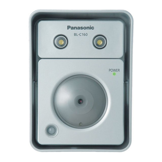
Camera Diagrams BL-C140 Front View Housing Indicator Lens Lens cover Rear View Safety wire hole DATA/POWER IN Stand mounting hole FACTORY DEFAULT RESET button Serial number and MAC address label See 1.1 Understanding the Camera Indicator in the Troubleshooting Guide on the CD-ROM for indicator meaning. - Page 8 BL-C160 Front View Housing Light Indicator Lens Lens cover Brightness sensor Built-in sensor (pyroelectric infrared sensor) Rear View Safety wire hole DATA/POWER IN Stand mounting hole FACTORY DEFAULT RESET button Serial number and MAC address label See 1.1 Understanding the Camera Indicator in the Troubleshooting Guide on the CD-ROM for indicator meaning. The brightness sensor determines when the light turns on.
-
Page 9: Choosing An Installation Location
Choosing an Installation Location Please read the following information about the camera’s motion detection feature and built-in sensor (BL-C160 only) before deciding where to mount the camera. Detection Features Motion Detection Feature The camera detects changes in the images being displayed. Active Motion Detection Range •... - Page 10 Detection Range Characteristics of the Motion Detection Feature • Motion detection becomes more difficult as it becomes darker. • The motion detection function works by detecting changes in contour and brightness in moving objects. This is done in order to reduce inaccurate detections due to changes in brightness. •...
- Page 11 Built-in Sensor (BL-C160 Only) The camera’s built-in sensor is a pyroelectric infrared sensor, which means it uses infrared rays to detect temperature differences within its range that are emitted naturally by people, animals, etc. The sensor can be used to trigger the camera to buffer (i.e., temporarily store) camera images in its memory.
- Page 12 Detection Range Characteristics of the Built-in Sensor • The built-in sensor can easily detect temperature changes when objects move sideways in front of the camera, but cannot easily detect temperature changes when objects move toward the front of the camera. When the camera is in a 20 °C (68 °F) environment Easy to detect Diffictult to detect...
-
Page 13: Mounting Location
• To ensure that camera images are displayed properly, do not mount the camera on a ceiling. • Do not mount the camera upside down. If the Panasonic logo is upside down, the camera is upside down. • Mount the camera where objects pass the camera from the sides. -
Page 14: Recommended Installation Locations
Recommended Installation Locations Top View Where it is easy to detect people coming off the street towards the property and where passing cars do not cause interference. It is easier to detect people when they pass in front of the camera. A sensor range cap can be attached to the camera to control the detection range. -
Page 15: Installation Examples
Installation Examples Example 1: For detecting people on your property Recommend Not Recommend Where it is easy to detect people coming off People or cars passing by on the street are the street towards the property and where easy to detect, but people approaching the passing cars do not cause interference. -
Page 16: Light Brightness (Bl-C160 Only)
Light Brightness (BL-C160 Only) The camera features a built-in light that can turn on automatically when it is Light dark, or when the camera’s motion detection or sensor features are triggered. The following brightness levels are measured 3 m (9 feet 10 inches) from the camera. -
Page 17: Connections
Connections Connect the camera to your router and to the power outlet as described below. • Before proceeding, confirm that your PC is connected to your router and can access the Internet. Also confirm that your router’s UPnP™ feature is enabled. (Most routers have UPnP™ turned off by default.) Wall Outside... -
Page 18: Camera Mounting
Camera Mounting Caution • Do not drive the screws into a soft material. Drive the screws into a secure area of the wall, such as a column, otherwise the camera may fall and be damaged. • Make sure you attach the safety wire when mounting the camera, to prevent the camera from falling. - Page 19 Mount the flexible stand firmly to the wall using screw A (included). • Do not drive the screws into a soft material. Drive the screws into a secure area of the wall, such as a column, otherwise the camera may fall and be damaged. •...
- Page 20 Wrap the included foam strip around the cable, insert it into the opening of the right-angle joint, and then wrap at least the first 50 mm (1 15/16 inches) of the cable using the included self bonding tape. • Leave about 10 mm (3/8 inches) of the foam exposed, as shown. •...
- Page 21 Secure the safety wire to the wall using screw A (included) and washer L (included). • When mounting to a hard surface like mortar or concrete, use an anchor to help secure the camera to the wall. • Leave some slack in the safety wire, as shown. Safety wire Washer L Screw A...
- Page 22 When mounting on a mortar or concrete surface • Prepare anchors for 4 mm (3/16 inch) diameter screws for mounting. A Place the flexible stand on the wall where you plan to mount the flexible stand and mark the points where you are going to make holes. B Make holes with an electric drill.
-
Page 23: Adjusting Range And Sensitivity
Adjusting Range and Sensitivity Preventing Sensor Interference (BL-C160 Only) If objects are interfering with the built-in sensor, use one of the included sensor range caps to cover the corresponding area of the sensor. For Built-in Sensors Example 1 If there are interfering objects (such as cars) on one side or corner of the screen, attach cap 1 or 2 to cover the desired area of the sensor. - Page 24 Example 2 If there are interfering objects (such as heat emitting devices) being displayed on both sides of the screen, use cap 3 to block the parts of the sensor that are detecting the interfering objects (in this case on the left and right-hand sides). Heat emitting device Other interfering object...
-
Page 25: Adjusting Motion Detection Sensitivity
Adjusting Motion Detection Sensitivity The sensitivity of the motion detection can be adjusted to match the installation environment. For more information, see 2.10 Adjusting Motion Detection Sensitivity in the Operating Instructions on the CD-ROM. -
Page 26: Adjusting Sensor Sensitivity (Bl-C160 Only)
Adjusting Sensor Sensitivity (BL-C160 Only) By adjusting the sensitivity of the built-in sensor, the detection range can change in the following ways. The temperature and other qualities of the camera location may affect the detection range. For more information, see 2.9 Adjusting Sensor Sensitivity (BL-C160) in the Operating Instructions on the CD-ROM. -
Page 27: Sensor Range Caps (Bl-C160 Only)
Sensor Range Caps (BL-C160 Only) When there are objects that you do not want to detect with the built-in sensor, a sensor range cap can be attached to the camera to control the detection range. There are 4 sensor range caps: the standard cap (attached at the time of purchase), cap 1, cap 2, and cap 3. - Page 28 Detection Ranges for the Sensor Range Caps Sensor range caps can be used to prevent detections when the temperature changes in certain areas of the detection range. Differing temperatures will affect how far the sensor can detect within the detection range. Confirm the different detection ranges in the following explanations. Please note that the below figures are a guide to the detection ranges when the Sensor Sensitivity is set to “Middle”...
- Page 29 Temperature: 0 °C (32 °F) Temperature: 30 °C (86 °F) Top View Top View Detection range Detection range About 4 m About 6 m (13 feet 1 inch) (19 feet 8 inches) Top View Top View Detection range Detection range About 4 m About 6 m (13 feet 1 inch)
- Page 30 Note...
- Page 31 Note...
- Page 32 © 2008 Panasonic Communications Co., Ltd. All Rights Reserved. PQQX16442YA KK0408CM1068...