Table of Contents
Advertisement
Advertisement
Table of Contents

Related Manuals for Asus H87I-PLUS


Summary of Contents for Asus H87I-PLUS
- Page 1 H87I-PLUS...
- Page 2 Product warranty or service will not be extended if: (1) the product is repaired, modified or altered, unless such repair, modification of alteration is authorized in writing by ASUS; or (2) the serial number of the product is defaced or missing.
-
Page 3: Table Of Contents
Contents Safety information ...................... iv About this guide ......................iv Package contents ....................... vi H87I-PLUS specifications summary ................. vi Product introduction Before you proceed ..................1-1 Motherboard overview ................. 1-1 Central Processing Unit (CPU) ..............1-3 System memory .................... 1-6 Expansion slots .................... -
Page 4: Safety Information
Safety information Electrical safety • To prevent electrical shock hazard, disconnect the power cable from the electrical outlet before relocating the system. • When adding or removing devices to or from the system, ensure that the power cables for the devices are unplugged before the signal cables are connected. If possible, disconnect all power cables from the existing system before you add a device. -
Page 5: Conventions Used In This Guide
Refer to the following sources for additional information and for product and software updates. ASUS websites The ASUS website provides updated information on ASUS hardware and software products. Refer to the ASUS contact information. Optional documentation Your product package may include optional documentation, such as warranty flyers, that may have been added by your dealer. -
Page 6: Package Contents
Dual-channel memory architecture * The maximum 16GB memory capacity can be supported with 8GB or above DIMMs. ASUS will update the memory QVL once the DIMMs are available in the market. ** Refer to www.asus.com for the latest Memory QVL (Qualified Vendors List). - Page 7 DRAM Fuse, ESD Guards, All 5K-Hour Solid Capacitors, and Stainless Steel Back I/O to ensure the best quality, reliability, and durability ASUS Digital Power Design - ASUS Digital Power Control: Digital Power Design for CPU and iGPU - ASUS 3 Phase Power Design ASUS DRAM Fuse...
- Page 8 H87I-PLUS specifications summary Internal I/O 1 x USB 3.0/2.0 connector supports additional 2 USB 3.0/2.0 ports (19-pin) connectors/ 2 x USB 2.0/1.1 connectors support additional 4 USB 2.0/1.1 ports buttons/switches 6 x SATA 6.0Gb/s connectors (yellow) 1 x CPU fan connector (4-pin)
-
Page 9: Product Introduction
The edge with external ports goes to the rear part of the chassis as indicated in the image below. 1.2.2 Screw holes Place four screws into the holes indicated by circles to secure the motherboard to the chassis. Do not overtighten the screws! Doing so can damage the motherboard. ASUS H87I-PLUS... -
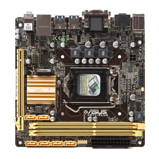
Page 10: Motherboard Layout
Place this side towards the rear of the chassis 1.2.3 Motherboard layout 17cm(6.7in) CLRTC KBMS_USB56 CHA_FAN CPU_FAN DIGI +VRM ATX12V Super SPDIFO _HDMI 1442 USB910 USB34 SB_PWR USB1314 Intel LAN_USB12 ® Intel I217 USB1112 BIOS USB78 AUDIO AAFP SPDIF_OUT PCIEX16 Chapter 1: Product introduction... -
Page 11: Central Processing Unit (Cpu)
Contact your retailer immediately if the PnP cap is missing, or if you see any damage to the PnP cap/socket contacts/motherboard components. ASUS will shoulder the cost of repair only if the damage is shipment/ transit-related. -
Page 12: Installing The Cpu
1.3.1 Installing the CPU Chapter 1: Product introduction... -
Page 13: Cpu Heatsink And Fan Assembly Installation
1.3.2 CPU heatsink and fan assembly installation Apply the Thermal Interface Material to the CPU heatsink and CPU before you install the heatsink and fan if necessary. To install the CPU heatsink and fan assembly ASUS H87I-PLUS... -
Page 14: System Memory
DDR3 DIMM sockets: Channel Sockets Channel A DIMM_A1 Channel B DIMM_B1 H87I-PLUS 240-pin DDR3 DIMM sockets 1.4.2 Memory configurations You may install 1GB, 2GB, 4GB, and 8GB unbuffered non-ECC DDR3 DIMMs into the DIMM sockets. Chapter 1: Product introduction... -
Page 15: Installing A Dimm
• The maximum 16GB memory capacity can be supported with 8GB or above DIMMs. ASUS will update the memory QVL once the DIMMs are available in the market. • The default memory operation frequency is dependent on its Serial Presence Detect (SPD), which is the standard way of accessing information from a memory module. -
Page 16: Expansion Slots
DIMM notch Unlocked retaining clip DIMM slot key A DIMM is keyed with a notch so that it fits in only one direction. DO NOT force a DIMM into a socket in the wrong direction to avoid damaging the DIMM. Firmly insert the DIMM into the socket until the retaining clips snap back in place and the DIMM is properly seated. -
Page 17: Installing An Expansion Card
This motherboard supports two PCI Express x16 graphics cards that comply with the PCI Express specifications. IRQ assignments for this motherboard PCIe x16 shared Intel I217 (LAN) shared On Chip SATA shared On Chip USB EHCI 1/2 shared On Chip USB XHCI shared HD Audio shared ASUS H87I-PLUS... -
Page 18: Jumpers
CLRTC Normal Clear RTC (Default) H87I-PLUS Clear RTC RAM To erase the RTC RAM: Turn OFF the computer and unplug the power cord. Move the jumper cap from pins 1-2 (default) to pins 2-3. Keep the cap on pins 2-3 for about 5-10 seconds, then move the cap back to pins 1-2. -
Page 19: Connectors
8-channel configurations, the function of this port becomes Front Speaker Out. Microphone port (pink). This port connects a microphone. To configure an 8-channel audio output: Use a chassis with HD audio module in the front panel to support an 8-channel audio output. ASUS H87I-PLUS 1-11... - Page 20 Audio 2, 4, 6, or 8-channel configuration Headset Port 4-channel 6-channel 8-channel 2-channel Light Blue (Rear panel) Line In Rear Speaker Out Rear Speaker Out Rear Speaker Out Lime (Rear panel) Line Out Front Speaker Out Front Speaker Out Front Speaker Out Pink (Rear panel) Mic In Mic In...
-
Page 21: Internal Connectors
PIN 1 HD-audio-compliant Legacy AC’97 pin definition compliant definition H87I-PLUS Front panel audio connector • We recommend that you connect a high-definition front panel audio module to this connector to avail of the motherboard’s high-definition audio capability. • If you want to connect a high-definition front panel audio module to this connector, set the Front Panel Type item in the BIOS setup to [HD]. - Page 22 The CPU_FAN connector supports a CPU fan of maximum 1A (12 W) fan power. Only the 4-pin CPU fan supports the ASUS Fan Xpert 2 feature. Intel H87 Serial ATA 6.0Gb/s connector (7-pin SATA6G_1~6 [yellow]) ®...
-
Page 23: Atx Power Connectors
• If you are uncertain about the minimum power supply requirement for your system, refer to the Recommended Power Supply Wattage Calculator at http://support.asus. com/PowerSupplyCalculator/PSCalculator.aspx?SLanguage=en-us for details. Speaker connector (4-pin SPEAKER) The 4-pin connector is for the chassis-mounted system warning speaker. The speaker allows you to hear system beeps and warnings. -
Page 24: Usb 2.0 Connectors 10-1 Pin Usb78/Usb910
These USB connectors comply with USB 2.0 specifications and supports up to 480Mbps connection speed. USB1112 USB78 H87I-PLUS USB2.0 connectors Never connect a 1394 cable to the USB connectors. Doing so will damage the motherboard! The USB 2.0 module is purchased separately. - Page 25 HDD_LED- PWR_LED+ HDD_LED+ PIN 1 H87I-PLUS System panel connector • System power LED (2-pin PWR_LED) This 2-pin connector is for the system power LED. Connect the chassis power LED cable to this connector. The system power LED lights up when you turn on the system power, and blinks when the system is in sleep mode.
-
Page 26: Onboard Leds
The illustration below shows the location of the onboard LED. SB_PWR Standby Power Powered Off H87I-PLUS Onboard LED 1-18 Chapter 1: Product introduction... -
Page 27: Software Support
Place the Support DVD into the optical drive. If Autorun is enabled in your computer, the DVD automatically displays the Specials screen which lists the unique features of your ASUS motherboard. Click Drivers, Utilities, AHCI/RAID Driver, Manual, Contact and Specials tabs to display their respective menus. -
Page 28: Bios Information
Managing and updating your BIOS Save a copy of the original motherboard BIOS file to a USB flash disk in case you need to restore the BIOS in the future. Copy the original motherboard BIOS using the ASUS Update utility. -
Page 29: Asus Ez Flash
2.1.2 ASUS EZ Flash 2 The ASUS EZ Flash 2 feature allows you to update the BIOS without using an OS-based utility. Before you start using this utility, download the latest BIOS file from the ASUS website at www.asus.com. To update the BIOS using EZ Flash 2: Insert the USB flash disk that contains the latest BIOS file to the USB port. -
Page 30: Asus Crashfree Bios 3 Utility
2.1.3 ASUS CrashFree BIOS 3 utility The ASUS CrashFree BIOS 3 is an auto recovery tool that allows you to restore the BIOS file when it fails or gets corrupted during the updating process. You can restore a corrupted BIOS file using the motherboard support DVD or a USB flash drive that contains the updated BIOS file. - Page 31 Insert the USB flash drive with the latest BIOS file and BIOS Updater to the USB port. Boot your computer. When the ASUS Logo appears, press <F8> to show the BIOS Boot Device Select Menu. Insert the support DVD into the optical drive and select the optical drive as the boot device.
- Page 32 Ensure to load the BIOS default settings to ensure system compatibility and stability. Select the Load Optimized Defaults item under the Exit menu. Refer to section 2.10 Exit Menu for details. • Ensure to connect all SATA hard disk drives after updating the BIOS file if you have disconnected them. ASUS H87I-PLUS...
-
Page 33: Bios Setup Program
The BIOS setup screens shown in this section are for reference purposes only, and may not exactly match what you see on your screen. • Visit the ASUS website at www.asus.com to download the latest BIOS file for this motherboard. •... -
Page 34: Advanced Mode
The Advanced Mode provides advanced options for experienced end-users to configure the BIOS settings. The figure below shows an example of the Advanced Mode. Refer to the following sections for the detailed configurations. To access the EZ Mode, click Exit, then select ASUS EZ Mode or press F7. ASUS H87I-PLUS... -
Page 35: Menu Bar
Back button Menu items Menu bar Configuration fields General help Last modified settings Pop-up window Navigation keys Submenu item Scroll bar Quick note Menu bar The menu bar on top of the screen has the following main items: My Favorites For saving the frequently-used system settings and configuration Main For changing the basic system configuration... -
Page 36: Submenu Items
<Enter> to display a list of options. Quick Note button This button allows you to enter notes of the activities that you have done in BIOS. Last Modified button This button shows the items that you last modified and saved in BIOS Setup. ASUS H87I-PLUS... -
Page 37: My Favorites
My Favorites MyFavorites is your personal space where you can easily save and access your favorite BIOS items. Adding items to My Favorites To add frequently-used BIOS items to My Favorites: Use the arrow keys to select an item that you want to add. When using a mouse, hover the pointer to the item. -
Page 38: Main Menu
RAM to clear the BIOS password. See section 1.6 Jumpers for information on how to erase the RTC RAM. • The Administrator or User Password items on top of the screen show the default Not Installed. After you set a password, these items show Installed. ASUS H87I-PLUS 2-11... -
Page 39: Administrator Password
Administrator Password If you have set an administrator password, we recommend that you enter the administrator password for accessing the system. Otherwise, you might be able to see or change only selected fields in the BIOS setup program. To set an administrator password: Select the Administrator Password item and press <Enter>. -
Page 40: Ai Tweaker Menu
Be cautious when changing the settings of the Ai Tweaker menu items. Incorrect field values can cause the system to malfunction. The configuration options for this section vary depending on the CPU and DIMM model you installed on the motherboard. ASUS H87I-PLUS 2-13... - Page 41 Scroll down to display the following items: Scroll down to display the following items: Target CPU Turbo-Mode Speed : xxxxMHz Displays the target CPU Turbo-Mode speed. Target DRAM Speed : xxxxMHz Displays the target DRAM speed. Target Cache Speed : xxxxMHz Displays the target Cache speed.
- Page 42 Memory Profile (X.M.P.) Technology, select this item to set the profiles supported by your memory modules for optimizing the system performance. 2.5.2 ASUS MultiCore Enhancement [Enabled] [Enabled] Default set to [Enabled] for maximum performance under XMP/Manual/ User-defined memory frequency mode.
- Page 43 4-Core Ratio Limit [Auto] This item becomes configurable only when the CPU Core Ratio is set to [Per Core] and allows you to set the 4 Core Ratio Limit. Select [Auto] to apply the CPU default Turbo Ratio setting or manually assign a 4-Core Ratio Limit value that is higher than or equal to the 3- Core Ratio Limit.
-
Page 44: Dram Timing Control
CPU Power Duty Control [T.Probe] DIGI + VRM Duty Control adjusts the current of every VRM phase and the thermal conditions of every component. [T. Probe] Select to maintain the VRM thermal balance. [Extreme] Select to maintain the current VRM balance. ASUS H87I-PLUS 2-17... -
Page 45: Cpu Power Management
CPU Current Capability [Auto] Allows you to configure the total power range, and extends the overclocking frequency range simultaneously. Configuration options: [Auto] [100%] [110%] [120%] [130%] [140%] Choose a higher value when overclocking, or under a high CPU loading for extra power support. - Page 46 Power Saving Level 1 Threshold [Auto] Lower value provides sufficient overclocking tolerance to enlarge the overclocking potential. Higher value provides better power-saving condition.Use <+> and <-> key to adjust the value. The values range from 0A to 80A at 1Amp increment. ASUS H87I-PLUS 2-19...
- Page 47 Power Saving Level 2 Threshold [Auto] Lower value provides sufficient overclocking tolerance to enlarge the overclocking potential. Higher value provides better power-saving condition.Use <+> and <-> key to adjust the value. The values range from 0A to 50A at 1Amp increment. Power Saving Level 3 Threshold [Auto] Lower value provides sufficient overclocking tolerance to enlarge the overclocking potential.
- Page 48 This item appears only when you set the CPU Graphics Voltage to [Manual Mode] and allows you to set the CPU Graphics Voltage override. Use the <+> or <-> keys to adjust the value, The values range from 0.001V to 1.920V with a 0.001V interval. ASUS H87I-PLUS 2-21...
- Page 49 The following items appear only when you set the CPU Graphics Voltage to [Offset Mode] or [Adaptive Mode]. Offset Mode Sign [+] To offset the voltage by a positive value. [–] To offset the voltage by a negative value. CPU Graphics Voltage Offset Use the <+>...
- Page 50 DRAM DATA REF Voltage on CHA [Auto] Allows you to set the DRAM DATA Reference Voltage on Channel A. The values range from 0.3950x to 0.6300x with a 0.0050x interval. Different ratio might enhance DRAM overclocking ability. ASUS H87I-PLUS 2-23...
-
Page 51: Advanced Menu
2.5.27 DRAM DATA REF Voltage on CHB [Auto] Allows you to set the DRAM DATA Reference Voltage on Channel B. The values range from 0.3950x to 0.6300x with a 0.0050x interval. Different ratio might enhance DRAM overclocking ability. 2.5.28 CPU Spread Spectrum [Auto] [Auto] Automatic configuration. -
Page 52: Cpu Configuration
Allows a hardware platform to perform adjacent cache line prefetching. [Disabled] Disables this function. Boot Performance mode [Max Non-Tu...] Allows you to select the performance state that the BIOS will set before OS handoff. Configuration options: [Max Non-Turbo performance] [Max Battery] [Turbo Performance] ASUS H87I-PLUS 2-25... -
Page 53: Pch Configuration
CPU Power Management Configuration This item allows you to manage and configure the CPU’s power. Enhanced Intel SpeedStep Technology [Enabled] Allows your system to adjust the processor’s voltage and cores frequency, resulting in decreased power consumption and heat production. [Disabled] The CPU runs at its default speed. -
Page 54: Intel Smart Connect Technology
Allows you to enable or disable the RapidStart Display/Restore function. Configuration options: [Enabled] [Disabled] Intel Smart Connect Technology ISCT Support [Disabled] Allow you to enable or disable the Intel Smart Connect Technology. Configuration options: ® [Enabled] [Disabled] ASUS H87I-PLUS 2-27... -
Page 55: Sata Configuration
2.6.3 SATA Configuration While entering Setup, the BIOS automatically detects the presence of SATA devices. The SATA Port items show Not Present if no SATA device is installed to the corresponding SATA port. SATA Mode Selection [AHCI] Allows you to set the SATA configuration. [Disabled] Disables the SATA function. -
Page 56: Graphics Configuration
Allows you to configure the memory configuration parameters. Memory Scrambler [Enabled] Allows you to enable or disable the Memory Scrambler support. Configuration options: [Enabled] [Disabled] Memory Remap [Enabled] Allows you to enable remapping the memory above 4GB. Configuration options: [Enabled] [Disabled] ASUS H87I-PLUS 2-29... -
Page 57: Usb Configuration
2.6.5 USB Configuration The items in this menu allow you to change the USB-related features. The USB Devices item shows the auto-detected values. If no USB device is detected, the item shows None. Legacy USB Support [Enabled] [Enabled] Enables the support for USB devices on legacy operating systems (OS). [Disabled] The USB devices can be used only for the BIOS setup program. -
Page 58: Onboard Devices Configuration
The system goes into either OFF or ON state, whatever the system state was before the AC power loss. Power On By PS/2 Keyboard [Disabled] [Disabled] Disables the Power On by a PS/2 keyboard. [Space Bar] Sets the Space Bar on the PS/2 keyboard to turn on the system. ASUS H87I-PLUS 2-31... -
Page 59: Network Stack
[Ctrl-Esc] Sets the Ctrl+Esc key on the PS/2 keyboard to turn on the system. [Power Key] Sets Power key on the PS/2 keyboard to turn on the system. This feature requires an ATX power supply that provides at least 1A on the +5VSB lead. Power On By PCIE [Disabled] [Disabled] Disables the PCIE/PCI devices to generate a wake-on-LAN feature of the... -
Page 60: Monitor Menu
The onboard hardware monitor automatically detects and displays the CPU and chassis fan speeds in rotations per minute (RPM). If the fan is not connected to the motherboard, the field shows N/A. Select Ignore if you do not wish to display the detected speed. ASUS H87I-PLUS 2-33... - Page 61 2.7.3 CPU Input Voltage (VCCIN), 3.3V Voltage, 5V Voltage, 12V Voltage The onboard hardware monitor automatically detects the voltage output through the onboard voltage regulators. Select Ignore if you do not want to detect this item. 2.7.4 CPU Q-Fan Control [Enabled] [Disabled] Disables the CPU Q-Fan control feature.
- Page 62 The values range from 60% to 100%. When the chassis temperature is under 20ºC, the chassis fan will operate at the minimum duty cycle. 2.7.6 Anti Surge Support [Disabled] This item allows you to enable or disable the Anti Surge function. Configuration options: [Disabled] [Enabled] ASUS H87I-PLUS 2-35...
-
Page 63: Boot Menu
Boot menu The Boot menu items allow you to change the system boot options. Scroll down to display the following items: 2-36 Chapter 2: Getting started... -
Page 64: Boot Configuration
Boot Logo Size Control [Auto] This item appears only when you set the Boot Logo Display item to [Enabled]. [Auto] Automatically adjust the boot logo size according to Windows ® requirements. [Full Screen] Display the boot logo in full screen. ASUS H87I-PLUS 2-37... - Page 65 Post Delay Time [3 sec] This item appears only when you set the Boot Logo Display item to [Enabled]. This item allows you to select a desired additional POST waiting time to easily enter the BIOS Setup. You can only execute the POST delay time during normal boot. The values range from 0 to 10 seconds.
-
Page 66: Secure Boot
The system verifies the PK before your system enters the OS. Delete PK Allows you to delete the PK from your system. Once the PK is deleted, all the system’s Secure Boot keys will not be active. Configuration options: [Yes] [No] ASUS H87I-PLUS 2-39... - Page 67 Load PK from File Allows you to load the downloaded PK from a USB storage device. [Yes] Load the default PK. [Enabled] Load from a USB storage device. The PK file must be formatted as a UEFI variable structure with time-based authenticated variable. KEK Management The KEK (Key-exchange Key or Key Enrollment Key) manages the Signature database (db) and Revoked Signature database (dbx).
-
Page 68: Boot Option Priorities
Press <F5> when ASUS Logo appears. • Press <F8> after POST. • To select the boot device during system startup, press <F8> when ASUS Logo appears. 2.8.11 Boot Override These items displays the available devices. The number of device items that appears on the screen depends on the number of devices installed in the system. -
Page 69: Tools Menu
<Enter> to display the submenu. 2.9.1 ASUS EZ Flash 2 Utility Allows you to run ASUS EZ Flash 2. Press [Enter] to launch the ASUS EZ Flash 2 screen. For more details, see section 2.1.2 ASUS EZ Flash 2. 2.9.2 ASUS O.C. -
Page 70: Exit Menu
This option allows you to exit the Setup program without saving your changes. When you select this option or if you press <Esc>, a confirmation window appears. Select Yes to discard changes and exit. ASUS EZ Mode This option allows you to enter the EZ Mode screen. Launch EFI Shell from filesystem device This option allows you to attempt to launch the EFI Shell application (shellx64.efi) from one of... -
Page 71: Appendices
Cet appareil est conforme aux normes CNR exemptes de licence d’Industrie Canada. Le fonctionnement est soumis aux deux conditions suivantes : (1) cet appareil ne doit pas provoquer d’interférences et (2) cet appareil doit accepter toute interférence, y compris celles susceptibles de provoquer un fonctionnement non souhaité de l’appareil. H87I-PLUS... -
Page 72: Canadian Department Of Communications Statement
ASUS Recycling/Takeback Services ASUS recycling and takeback programs come from our commitment to the highest standards for protecting our environment. We believe in providing solutions for you to be able to responsibly recycle our products, batteries, other components as well as the packaging materials. -
Page 73: Asus Contact Information
+1-812-282-3777 +1-510-608-4555 Web site usa.asus.com Technical Support Telephone +1-812-282-2787 Support fax +1-812-284-0883 Online support support.asus.com ASUS COMPUTER GmbH (Germany and Austria) Address Harkort Str. 21-23, D-40880 Ratingen, Germany +49-2102-959911 Web site www.asus.de Online contact www.asus.de/sales Technical Support Telephone +49-1805-010923* Support Fax... - Page 74 Appendices...