Table of Contents
Advertisement
Advertisement
Table of Contents

Related Manuals for Asus H81M-V3


Summary of Contents for Asus H81M-V3
- Page 1 H81M-V3...
- Page 2 Product warranty or service will not be extended if: (1) the product is repaired, modified or altered, unless such repair, modification of alteration is authorized in writing by ASUS; or (2) the serial number of the product is defaced or missing.
-
Page 3: Table Of Contents
Contents Safety information ....................... 4 About this guide ......................4 Package contents ......................6 H81M-V3 specifications summary ................6 Chapter 1: Product introduction Before you proceed ..................1-1 Motherboard overview ................. 1-2 Central Processing Unit (CPU) ..............1-4 System memory .................... 1-7 Expansion slots .................. -
Page 4: Safety Information
Safety information Electrical safety • To prevent electrical shock hazard, disconnect the power cable from the electrical outlet before relocating the system. • When adding or removing devices to or from the system, ensure that the power cables for the devices are unplugged before the signal cables are connected. If possible, disconnect all power cables from the existing system before you add a device. -
Page 5: Conventions Used In This Guide
Refer to the following sources for additional information and for product and software updates. ASUS websites The ASUS website provides updated information on ASUS hardware and software products. Refer to the ASUS contact information. Optional documentation Your product package may include optional documentation, such as warranty flyers, that may have been added by your dealer. -
Page 6: Package Contents
DDR3 1600 MHz and higher memory modules on ® XMP mode will run at the maximum transfer rate of DDR3 1600 MHz. • Refer to www.asus.com for the latest Memory QVL (Qualified Vendors List). • When you install a total memory of 4GB capacity or more, Windows 32-bit ®... - Page 7 - 8 x USB2.0/1.1 ports (6 ports at midboard, 2 ports at back panel) ASUS unique ASUS 5X Protection features - ASUS motherboards safeguard your PC with 5X Protection: DIGI+VRM, DRAM Fuse, ESD Guards, High-Quality 5K-Hour Solid Capacitors, and Stainless Steel Back ASUS Digital Power Design...
- Page 8 H81M-V3 specifications summary ASUS unique ASUS Quiet Thermal Solution features - ASUS Fanless Design: Stylish Heatsink solution - ASUS Fan Xpert ASUS Q-Design - ASUS Q-Slot - ASUS EZ DIY - ASUS CrashFree BIOS 3 - ASUS EZ Flash 2...
-
Page 9: Chapter 1: Product Introduction
• Unplug the power cord from the wall socket before touching any component. • Before handling components, use a grounded wrist strap or touch a safely grounded object or a metal object, such as the power supply case, to avoid damaging them due to static electricity. • Hold components by the edges to avoid touching the ICs on them. • Whenever you uninstall any component, place it on a grounded antistatic pad or in the bag that came with the component. • Before you install or remove any component, ensure that the ATX power supply is switched off or the power cord is detached from the power supply. Failure to do so may cause severe damage to the motherboard, peripherals, or components. ASUS H81M-V3... -
Page 10: Motherboard Overview
1.2.2 Screw holes Place six screws into the holes indicated by circles to secure the motherboard to the chassis. Do not overtighten the screws! Doing so can damage the motherboard. Place this side towards the rear of the chassis H81M-V3 Chapter 1: Product introduction... -
Page 11: Motherboard Layout
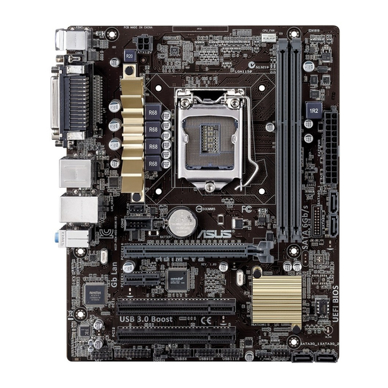
AAFP CHASSIS F_PANEL Connectors/Jumpers/Slots/LED Serial port connector (10-1 pin COM2) 1-19 ATX power connectors (24-pin ATXPWR, 4-pin ATX12V) 1-15 CPU and chassis fan connectors (4-pin CPU_FAN, 4-pin CHA_FAN) 1-18 Intel LGA1150 CPU socket ® DDR3 DIMM slots Intel H81 Serial ATA 6.0Gb/s connector (7-pin SATA6G_1~2) 1-17 ® Intel H81 Serial ATA 3.0Gb/s connector (7-pin SATA3G_1~2) 1-17 ® System panel connector (10-1 pin F_PANEL) 1-21 Speaker connector (4-pin SPEAKER) 1-19 USB 2.0 connectors (10-1 pin USB56, USB910, USB1112) 1-20 Chassis intrusion connector (4-1 pin CHASSIS) 1-22 Clear RTC RAM (2-pin CLRTC) 1-12 TPM header (20-1 pin TPM) 1-16 Front panel audio connector (10-1 pin AAFP) 1-16 Digital audio connector (4-1 pin SPDIF_OUT) 1-22 ASUS H81M-V3... -
Page 12: Central Processing Unit (Cpu)
Central Processing Unit (CPU) This motherboard comes with a surface mount LGA1150 socket designed for the Intel ® 4th/5th generation Core™ i7 / Core™ i5 / Core™ i3, Pentium , and Celeron processors. ® ® H81M-V3 H81M-V3 CPU socket LGA1150 Unplug all power cables before installing the CPU. • Upon purchase of the motherboard, ensure that the PnP cap is on the socket and the socket contacts are not bent. Contact your retailer immediately if the PnP cap is missing, or if you see any damage to the PnP cap/socket contacts/motherboard components. ASUS will shoulder the cost of repair only if the damage is shipment/ transit-related. • Keep the cap after installing the motherboard. ASUS will process Return Merchandise Authorization (RMA) requests only if the motherboard comes with the cap on the LGA1150 socket. • The product warranty does not cover damage to the socket contacts resulting from incorrect CPU installation/removal, or misplacement/loss/incorrect removal of the PnP cap. Chapter 1: Product introduction... - Page 13 1.3.1 Installing the CPU ASUS H81M-V3...
-
Page 14: Cpu Heatsink And Fan Assembly Installation
1.3.2 CPU heatsink and fan assembly installation Apply the Thermal Interface Material to the CPU heatsink and CPU before you install the heatsink and fan if necessary. To install the CPU heatsink and fan assembly Chapter 1: Product introduction... -
Page 15: System Memory
To uninstall the CPU heatsink and fan assembly System memory 1.4.1 Overview This motherboard comes with two Double Data Rate 3 (DDR3) Dual Inline Memory Modules (DIMM) sockets. A DDR3 module has the same physical dimensions as a DDR2 DIMM but is notched differently to prevent installation on a DDR2 DIMM socket. DDR3 modules are developed for better performance with less power consumption. Channel Sockets Channel A DIMM_A1 Channel B DIMM_B1 H81M-V3 H81M-V3 240-pin DDR3 DIMM sockets ASUS H81M-V3... -
Page 16: Memory Configurations
1.4.2 Memory configurations You may install 1GB, 2GB, 4GB, and 8GB unbuffered non-ECC DDR3 DIMMs into the DIMM sockets. • You may install varying memory sizes in Channel A and Channel B. The system maps the total size of the lower-sized channel for the dual-channel configuration. Any excess memory from the higher-sized channel is then mapped for single-channel operation. • Always install DIMMs with the same CAS latency. For optimal compatibility, we recommend that you install memory modules of the same version or date code (D/C) from the same vendor. Check with the retailer to get the correct memory modules. • Memory module with memory frequency higher than 2133 MHz and its corresponding timing or the loaded XMP Profile is not the JEDEC memory standard. The stability and compatibility of these memory modules depend on the CPU's capabilities and other installed devices. • Due to Intel® chipset limitation, DDR3 1600 MHz and higher memory modules on XMP mode will run at the maximum transfer rate of DDR3 1600 MHz. • Due to the memory address limitation on 32-bit Windows OS, when you install 4GB ® or more memory on the motherboard, the actual usable memory for the OS can be about 3GB or less. For effective use of memory, we recommend that you do any of the following: - Use a maximum of 3GB system memory if you are using a 32-bit Windows OS. ® - I nstall a 64-bit Windows OS when you want to install 4GB or more on the ® motherboard. • This motherboard does not support DIMMs made up of 512Mb (64MB) chips or less. •... -
Page 17: Installing A Dimm
1.4.3 Installing a DIMM To install a DIMM To remove a DIMM ASUS H81M-V3... -
Page 18: Expansion Slots
Expansion slots In the future, you may need to install expansion cards. The following sub-sections describe the slots and the expansion cards that they support. Unplug the power cord before adding or removing expansion cards. Failure to do so may cause you physical injury and damage motherboard components. 1.5.1 Installing an expansion card To install an expansion card: Before installing the expansion card, read the documentation that came with it and make the necessary hardware settings for the card. Remove the system unit cover (if your motherboard is already installed in a chassis). -
Page 19: Irq Assignments For This Motherboard
USB2.0 controller 2 – – – – shared – – – HD audio – – – – – – shared – SATA controller 1 – – – shared – – – – SATA controller 2 – – – shared – – – – ASUS H81M-V3 1-11... -
Page 20: Headers
Headers Clear RTC RAM (2-pin CLRTC) This header allows you to clear the Real Time Clock (RTC) RAM in CMOS. You can clear the CMOS memory of date, time, and system setup parameters by erasing the CMOS RTC RAM data. The onboard button cell battery powers the RAM data in CMOS, which include system setup information such as system passwords. CLRTC H81M-V3 Normal Clear CMOS (Default) Values (Short) H81M-V3 Clear RTC RAM To erase the RTC RAM: Turn OFF the computer and unplug the power cord. Use a metal object such as a screwdriver to short the two pins. Plug the power cord and turn ON the computer. Hold down the <Del> key during the boot process and enter BIOS setup to re- enter data. • If the steps above do not help, remove the onboard battery and short the two pins again to clear the CMOS RTC RAM data. After clearing the CMOS, reinstall the battery. • You do not need to clear the RTC when the system hangs due to overclocking. For system failure due to overclocking, use the CPU Parameter Recall (C.P.R.) feature. -
Page 21: Connectors
LAN port LED indications Speed Activity Link Activity/Link LED Speed LED Status Description Status Description No link 10Mbps connection Orange Linked ORANGE 100Mbps connection Orange (Blinking) Data activity GREEN 1Gbps connection LAN port Orange (Blinking Ready to wake up then steady) from S5 mode ASUS H81M-V3 1-13... - Page 22 Line In port (light blue). This port connects to the tape, CD, DVD player, or other audio sources. Line Out port (lime). This port connects to a headphone or a speaker. In the 4.1, 5.1 and 7.1-channel configurations, the function of this port becomes Front Speaker Out. Microphone port (pink). This port connects to a microphone. Refer to the audio configuration table for the function of the audio ports in 2.1, 4.1, 5.1, or 7.1-channel configuration. Audio 2.1, 4.1, 5.1, or 7.1-channel configuration Headset Port 4.1-channel 5.1-channel 7.1-channel 2.1-channel Light Blue (Rear Line In Rear Speaker Out Rear Speaker Out Rear Speaker Out panel) Lime (Rear panel)
-
Page 23: Internal Connectors
-5 Volts Power OK PIN 1 +5 Volts +5 Volts PSON# H81M-V3 +3 Volts -12 Volts +3 Volts +3 Volts PIN 1 H81M-V3 ATX power connectors • For a fully configured system, we recommend that you use a power supply unit (PSU) that complies with ATX 12V Specification 2.0 (or later version) and provides a minimum power of 350W. • DO NOT forget to connect the 4-pin ATX +12V power plug. Otherwise, the system will not boot up. • We recommend that you use a PSU with higher power output when configuring a system with more power-consuming devices or when you intend to install additional devices. The system may become unstable or may not boot up if the power is inadequate. - Page 24 Front panel audio connector (10-1 pin AAFP) This connector is for a chassis-mounted front panel audio I/O module that supports either HD Audio or legacy AC`97 audio standard. Connect one end of the front panel audio I/O module cable to this connector. AAFP PIN 1 H81M-V3 HD-audio-compliant Legacy AC’97 pin definition compliant definition H81M-V3 Front panel audio connector • We recommend that you connect a high-definition front panel audio module to this connector to avail of the motherboard’s high-definition audio capability. • If you want to connect a high-definition front panel audio module to this connector, set the Front Panel Type item in the BIOS setup to [HD]. If you want to connect an AC’97 front panel audio module to this connector, set the item to [AC97]. By default, this connector is set to [HD]. See section 2.6.7 Onboard Devices Configuration for details. 1-16...
- Page 25 Intel H81 Serial ATA 6.0Gb/s connector (7-pin SATA6G_1~2 [gray]) ® This connector connects to Serial ATA 6.0 Gb/s hard disk drives via Serial ATA 6.0 Gb/s signal cables. H81M-V3 H81M-V3 SATA 6.0Gb/s connectors When using hot-plug and NCQ, set the SATA Mode Selection item in the BIOS to [AHCI]. See section 2.6.3 SATA Configuration for details. Intel ® H81 Serial ATA 3.0Gb/s connector (7-pin SATA3G_1~2) This connector connects to Serial ATA 3.0 Gb/s hard disk drives via Serial ATA 3.0 Gb/s signal cables. H81M-V3 H81M-V3 SATA 3.0Gb/s connectors When using hot-plug and NCQ, set the SATA Mode Selection item in the BIOS to [AHCI].
- Page 26 CPU and chassis fan connectors (4-pin CPU_FAN, 4-pin CHA_FAN) Connect the fan cables to the fan connectors on the motherboard, ensuring that the black wire of each cable matches the ground pin of the connector. CPU_FAN CHA_FAN(DC mode) CHA_FAN (PWM mode) H81M-V3 H81M-V3 Fan connectors • Do not forget to connect the fan cables to the fan connectors. Insufficient air flow inside the system may damage the motherboard components. These are not jumpers! Do not place jumper caps on the fan connectors! • Ensure that the CPU fan cable is securely installed on the CPU fan connector. • The CPU_FAN connector supports the CPU fan of maximum 1A (12 W) fan power.
- Page 27 Serial port connector (10-1 pin COM2) This connector is for a serial (COM) port. Connect the serial port module cable to this connector, then install the module to a slot opening at the back of the system chassis. COM2 PIN 1 H81M-V3 H81M-V3 Serial port (COM2) connector The COM module is purchased separately. Speaker connector (4-pin SPEAKER) The 4-pin connector is for the chassis-mounted system warning speaker. The speaker allows you hear system beeps and warnings. SPEAKER H81M-V3 PIN 1 H81M-V3 Speaker Out connector ASUS H81M-V3...
- Page 28 USB 2.0 connectors (10-1 pin USB56, USB910, USB1112) These connectors are for USB 2.0 ports. Connect the USB module cable to any of these connectors, then install the module to a slot opening at the back of the system chassis. These USB connectors comply with USB 2.0 specifications and supports up to 480Mbps connection speed. USB56 USB910 USB1112 PIN 1 PIN 1 PIN 1 H81M-V3 H81M-V3 USB2.0 connectors Never connect a 1394 cable to the USB connectors. Doing so will damage the motherboard! The USB 2.0 module is purchased separately. 1-20 Chapter 1: Product introduction...
-
Page 29: System Panel Connector
System panel connector (10-1 pin PANEL) This connector supports several chassis-mounted functions. F_PANEL +PWR LED PWR BTN PIN 1 H81M-V3 +HDD_LED RESET H81M-V3 System panel connector • System power LED (2-pin PWR_LED) This 2-pin connector is for the system power LED. Connect the chassis power LED cable to this connector. The system power LED lights up when you turn on the system power, and blinks when the system is in sleep mode. • Hard disk drive activity LED (2-pin HDD_LED) This 2-pin connector is for the HDD Activity LED. Connect the HDD Activity LED cable to this connector. The HDD LED lights up or flashes when data is read from or written to the HDD. • ATX power button/soft-off button (2-pin PWR_BTN) This connector is for the system power button. -
Page 30: Chassis Intrusion Connector
Digital audio connector (4-1 pin SPDIF_OUT) This connector is for an additional Sony/Philips Digital Interface (S/PDIF) port. SPDIF_OUT H81M-V3 H81M-V3 Digital audio connector The S/PDIF module is purchased separately. Chassis intrusion connector (4-1 pin CHASSIS) This connector is for a chassis-mounted intrusion detection sensor or switch. Connect one end of the chassis intrusion sensor or switch cable to this connector. The chassis intrusion sensor or switch sends a high-level signal to this connector when a chassis component is removed or replaced. The signal is then generated as a chassis intrusion event. By default, the pin labeled “Chassis Signal” and “Ground” are shorted with a jumper cap. Remove the jumper caps only when you intend to use the chassis intrusion... -
Page 31: Software Support
® ® Vista Service Pack 1 or later versions before installing the drivers for better compatibility and system stability. 1.8.2 Support DVD information The Support DVD that comes with the motherboard package contains the drivers, software applications, and utilities that you can install to avail all motherboard features. The contents of the Support DVD are subject to change at any time without notice. Visit the ASUS website at www.asus.com for updates. To run the Support DVD Place the Support DVD into the optical drive. If Autorun is enabled in your computer, the DVD automatically displays the Specials screen. Click Drivers, Utilities, AHCI Driver, Manual, and Contact tabs to display their respective menus. The following screen is for reference only. Click an icon to display Support DVD/motherboard information... - Page 32 1-24 Chapter 1: Product introduction...
-
Page 33: Chapter 2: Bios Information
Service Provider). 2.1.2 ASUS EZ Flash 2 The ASUS EZ Flash 2 feature allows you to update the BIOS without using an OS‑based utility. Before you start using this utility, download the latest BIOS file from the ASUS website at www.asus.com. -
Page 34: Asus Crashfree Bios 3 Utility
2.1.3 ASUS CrashFree BIOS 3 utility The ASUS CrashFree BIOS 3 is an auto recovery tool that allows you to restore the BIOS file when it fails or gets corrupted during the updating process. You can restore a corrupted BIOS file using the motherboard support DVD or a USB flash drive that contains the updated BIOS file. -
Page 35: Asus Bios Updater
2.1.4 ASUS BIOS Updater The ASUS BIOS Updater allows you to update BIOS in DOS environment. This utility also allows you to copy the current BIOS file that you can use as a backup when the BIOS fails or gets corrupted during the updating process. - Page 36 Updating the BIOS file To update the BIOS file using BIOS Updater: At the FreeDOS prompt, type bupdater /pc /g and press <Enter>. The BIOS Updater screen appears as below. ASUSTek BIOS Updater for DOS V1.30 BOARD: H81M-V3 VER: 0316 DATE: 04/11/2014 H81MV3.CAP 8390656 2014-04-11 17:30:48 Press <Tab>...
-
Page 37: Bios Setup Program
Using the power button, reset button, or the <Ctrl>+<Alt>+<Del> keys to force reset from a running operating system can cause damage to your data or system. We recommend to always shut down the system properly from the operating system. ASUS H81M-V3... -
Page 38: Bios Menu Screen
The BIOS setup screens shown in this section are for reference purposes only, and may not exactly match what you see on your screen. • Visit the ASUS website at www.asus.com to download the latest BIOS file for this motherboard. •... - Page 39 Power Saving mode • The boot device options vary depending on the devices you installed to the system. • The Boot Menu(F8) button is available only when the boot device is installed to the system. ASUS H81M-V3 2‑7...
- Page 40 BIOS settings. The figure below shows an example of the Advanced Mode. Refer to the following sections for the detailed configurations. To access the EZ Mode, click Exit, then select ASUS EZ Mode or press F7. Menu items Menu bar...
-
Page 41: My Favorites
Favorites page. You cannot add the following items to My Favorites: • Items with submenu options • User‑configurable items such as language and boot device order • Configuration items such as Memory SPD Information, system time and date ASUS H81M-V3... -
Page 42: Main Menu
Main menu The Main menu screen appears when you enter the Advanced Mode of the BIOS Setup program. The Main menu provides you an overview of the basic system information, and allows you to set the system date, time, language, and security settings. •... -
Page 43: Ai Tweaker Menu
Be cautious when changing the settings of the Ai Tweaker menu items. Incorrect field values can cause the system to malfunction. The configuration options for this section vary depending on the CPU and DIMM model you installed on the motherboard. Scroll down to display the other items. ASUS H81M-V3 2-11... -
Page 44: Advanced Menu
Advanced menu The Advanced menu items allow you to change the settings for the CPU and other system devices. Be cautious when changing the settings of the Advanced menu items. Incorrect field values can cause the system to malfunction. Monitor menu The Monitor menu displays the system temperature/power status, and allows you to change the fan settings. -
Page 45: Boot Menu
Boot menu The Boot menu items allow you to change the system boot options. Scroll down to display the other items. ASUS H81M-V3 2‑13... -
Page 46: Tools Menu
Tools menu The Tools menu items allow you to configure options for special functions. Select an item then press <Enter> to display the submenu. 2.10 Exit menu The Exit menu items allow you to load the optimal default values for the BIOS items, and save or discard your changes to the BIOS items. -
Page 47: Appendices
Cet appareil est conforme aux normes CNR exemptes de licence d’Industrie Canada. Le fonctionnement est soumis aux deux conditions suivantes : (1) cet appareil ne doit pas provoquer d’interférences et (2) cet appareil doit accepter toute interférence, y compris celles susceptibles de provoquer un fonctionnement non souhaité de l’appareil. ASUS H81M-C R2.0... -
Page 48: Canadian Department Of Communications Statement
ASUS Recycling/Takeback Services ASUS recycling and takeback programs come from our commitment to the highest standards for protecting our environment. We believe in providing solutions for you to be able to responsibly recycle our products, batteries, other components as well as the packaging materials. -
Page 49: Asus Contact Information
+1-510-739-3777 +1-510-608-4555 Web site http://www.asus.com/us Technical Support Support fax +1-812-284-0883 General support +1-812-282-2787 Online support http://www.service.asus.com ASUS COMPUTER GmbH (Germany and Austria) Address Harkort Str. 21-23, D-40880 Ratingen, Germany +49-2102-959931 Web site http://www.asus.com/de Online contact http://eu-rma.asus.com/sales Technical Support Telephone +49-2102-5789555... - Page 50 Appendices...