
Related Manuals for Planet WGSW-404


Summary of Contents for Planet WGSW-404
-
Page 1: User Manual
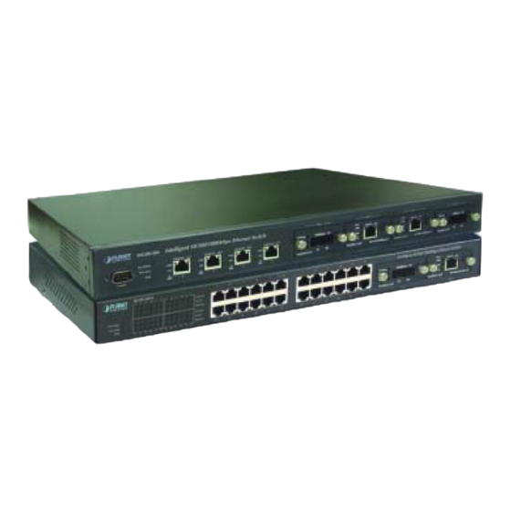
Intelligent Gigabit Ethernet Stackable / Routing Switch 24 10/100 Mbps Ports + 2 modules slot WGSW-2402A 4-port Gigabit Ethernet + 4-slot WGSW-404 User Manual... - Page 2 Disclaimer PLANET Technology does not warrant that the hardware will work properly in all environments and applications, and makes no warranty and representation, either implied or expressed, with respect to the quality, performance, merchantability, or fitness for a particular purpose.
-
Page 3: Table Of Contents
2.1.2 LEDs of WGSW-2402A ......................7 2.1.3 Rear Panel of WGSW-2402A ....................8 2.2 WGSW-404 H .................... 8 ARDWARE ESCRIPTION 2.2.1 Front Panel of WGSW-404 ....................8 2.2.2 LEDs of WGSW-404......................9 2.2.3 Rear Panel of WGSW-404....................10 2.3 M ....................10 ODULE... - Page 4 4.1 L ......................20 OGGING ON TO THE WITCH 4.2 N ................21 AVIGATING HROUGH THE ONSOLE NTERFACE 4.3 P ................21 ERFORMING ASIC ANAGEMENT CTIVITIES 4.3.1 General Management Configuration ................... 22 4.3.1.1 Changing the System Name......................23 4.3.1.2 Changing the Contact and Location .................... 24 4.3.1.3 Changing the Administration Password..................
- Page 5 5.2.2.7 Deleting Ports..........................67 5.2.3 Configuring PVID ......................... 67 5.3 IP M ....................69 ULTICAST ROUP ERSPECTIVE 5.4 MAC A ....................... 73 DDRESS ERSPECTIVE 5.5 P ........................74 ERSPECTIVE 5.5.1 Per Port VLAN Activities ...................... 75 5.5.2 Scrolling Through MAC Addresses ..................77 5.5.3 Hiding or Displaying the Port Column..................
- Page 6 5.14 P ........................146 IRRORING 5.15 S ................150 ETTING UALITY OF ERVICE ARAMETERS 5.15.1 Basic concept ........................150 5.15.1.1 QoS model ..........................150 5.15.1.2 Four QoS Profile........................152 5.15.1.3 Delay Bound..........................153 5.15.1.4 Strict Priority and Best Effort ....................153 5.15.1.5 Weighted Fair Queuing......................
- Page 7 6.4.2 Configuring LAN Ports ....................... 205 6.4.3 Console Port Configuration....................209 CHAPTER 7 PERFORMING ADVANCED SETUP ACTIVITIES............. 213 7.1 MAC A ..................... 214 DDRESS ANAGEMENT 7.1.1 Per VLAN View ........................215 7.1.2 Per Port View ........................216 7.1.3 Individual MAC View ......................218 7.2 IP N ..........................
- Page 8 8.3.1 RMON Groups Supported ....................261 8.3.2 Bridge Groups Supported ....................261 8.4 PLANET P MIB........................ 262 RIVATE APPENDIX A CABLE SPECIFICATIONS ..................263 APPENDIX B EXAMPLE OF STACKING SWITCHES..............265 APPENDIX C VLAN ......................... 267 C.1 A VLAN ..................... 268 SSIGNING ORTS TO C.1.1 VLAN Classification......................
-
Page 9: Chapter 1 Introduction
IP. You can stack 8 WGSW-2402A to get up to 192 100Base-TX ports plus 2 Gigabit port or 8 WGSW-404 to get 50 Gigabit ports in single stack. Mix them in a single stack is also possible to get maximum flexibility. -
Page 10: Features
One Intelligent Gigabit Ethernet Switch One Power Cord Rack Mounting Brackets One Serial/Console Cable User’s manual CD Quick Installation Guide If any of these pieces are missing or damaged, please contact your dealer immediately, if possible, retain the carton including the original packing material, and use them against to repack the product in case there is a need to return it to us for repair. -
Page 11: Specification
1.3 Specification Product WGSW-2402A WGSW-404 Hardware Specification 24 10/ 100Base-TX RJ-45 10/100/1000Base-T RJ-45 Ports Auto-MDI/MDI-X ports Auto-MDI/MDI-X ports Module Slot for 1000Base-SX/T and 100Base-FX modules Through Ethernet interface. Up to 8 units can be managed by Stack Interface single IP 12.8Gbps... -
Page 12: How To Use This Manual
Gigabit ports Supports delay bound, strict priority, WFQ (Weighted Fair QoS Scheduling Queuing) and best effort service disciplines Supports WRED (Weighted Random Early Detection) drop Congestion Avoidance threshold management 10 levels of rate (10 to 100%) Rate Control configurable on 10/100Mbps port Standards Conformance FCC Part 15 Class A, CE... - Page 13 Chapter 8, SNMP and RMON Management allows you to access the Switch using SNMP management feature. Appendix provides cable specification and more information regarding to stack and VLAN. - 5 -...
-
Page 14: Chapter 2 Installation
CHAPTER 2 INSTALLATION This Chapter describes the hardware function of the Switches and shows how to install it on the desktop or shelf. Basic knowledge of networking is assumed. Read this chapter completely before continuing. 2.1 WGSW-2402A Hardware Description 2.1.1 Front Panel of WGSW-2402A The front panel of the Switch has 24 RJ-45 ports for 10/100 Mbps in the middle. -
Page 15: Leds Of Wgsw-2402A
2.1.2 LEDs of WGSW-2402A The LEDs indicate the status of 10/100 Mbps Ethernet ports, Over Heat, Fan Failure and Power. Figure 2-2 shows the LED panel of the Switch. Table 2-2 shows the functions of power and status LEDs. Table 2-3 shows the functions of the port status LEDs. -
Page 16: Rear Panel Of Wgsw-2402A
2.2.1 Front Panel of WGSW-404 The front panel of the WGSW-404 has 4 RJ-45 ports for 10/100/1000 Mbps in the middle. The port status LEDs are indicated at the left. The expansion modules are situated at the right. Figure 2-3 shows the Switch’s front panel. -
Page 17: Leds Of Wgsw-404
Ports 100Base-FX expansion module and use fiber optic or category 5 cabling. 2.2.2 LEDs of WGSW-404 The LEDs indicate the status of 10/100/1000 Mbps Ethernet ports, Over Heat, Fan Failure and Power. The LEDs are explained in the following tables. -
Page 18: Rear Panel Of Wgsw-404
2.2.3 Rear Panel of WGSW-404 The rear panel of WGSW-404 has a power connector, a Buzzer button and a console port. Figure 2-3 shows a rear panel of the Switch. Table 2-5 explains the function of the ports shown in the Figure 2-4. -
Page 19: 100Base-Fx Expansion Module
2-6 G IGURE IGABIT XPANSION ODULE WGSW-C1GT Module Status LEDs WGSW-C1SX Module Status LEDs 2-9 WGSW-C1GT/SX S ABLE TATUS WGSW-C1GT Color Function Lights to indicate that the Switch is sending or receiving Green 1000 data at 1000 Mbps. Lights to indicate that the Switch is sending or receiving Green data at 100 Mbps. -
Page 20: Installing The Switch
2-7 100B -FX E IGURE XPANSION ODULE WGSW-C1ST Module Status LEDs WGSW-C1SC Module Status LEDs 2-11 100B ABLE MODULE TATUS WGSW-C1SC / WGSW-C1ST Color Function Lights to indicate that receiver of fibre port is in normal Green optical input levels. Lights to indicate that the connection is acting. -
Page 21: Pre-Installation Considerations
2.4.1 Pre-Installation Considerations Fast Ethernet Topology Considerations If you will be using the Switch for Fast Ethernet (100 Mbps) operation, observe the following guidelines: The maximum unshielded twisted-pair (UTP) cable length is 100 meters (328 feet) over Category 5 cable. Single-repeater topologies permit a total network span of 325 meters (1066 feet). -
Page 22: Rack-Mounting
2.4.3 Rack-Mounting The following procedure describes how to install the Switch in a standard 19-inch rack. Disconnect all cables from the Switch. Remove all adhesive pads from the bottom of the Switch. Step 1 Place the Switch right side up on a hard flat surface, with the front panel facing you. Step 2 Locate a mounting bracket over the mounting holes on one side of the Switch 2-8 L IGURE... -
Page 23: Chapter 3 Configuration
CHAPTER 3 CONFIGURATION This chapter explains the methods that you can use to configure management access to the Switch. It describes the types of management applications and the communication and management protocols that deliver data between your management device (workstation or personal computer) and the system. It also contains information about port connection options. -
Page 24: Administration Console
Can be accessed from any location May encounter delay times on Most visually appealing poor connections Communicates with switch functions at Requires SNMP manager the MIB level software Based on open standards Least visually appealing of all three methods SNMP Agent Some settings require calculations Security can be compromised (hackers need only know the... -
Page 25: Modem Port Access
3.1.3 Modem Port Access You can access the Switch’s administration console from a PC or Macintosh using an external modem attached to the console (serial) port. The Switch management program provides a Console Port screen, accessible from the Basic Management screen, that lets you configure parameters for modem access (see Chapter 4 Menu-Driven Console Management). -
Page 26: Snmp-Based Network Management
3.3 SNMP-Based Network Management You can use an external SNMP-based application to configure and manage the Switch. This management method requires the SNMP agent on the Switch and the SNMP Network Management Station to use the same community string. This management method, in fact, uses two community strings: the get community string and the set community string. -
Page 27: Management Architecture
3.4.3 Management Architecture All of the management application modules use the same Messaging Application Programming Interface (MAPI). By unifying management methods with a single MAPI, configuration parameters set using one method (console port, for example) are immediately displayable by the other management methods (for example, SNMP agent of Web browser). -
Page 28: Chapter 4 Menu-Driven Console Management
RS-232 port or remotely via a Telnet session. This chapter describes how to configure the Switch using its menu-driven console. The figures in this chapter will base on WGSW-2402A, for WGSW-404, however, the setup steps are the same. 4.1 Logging on to the Switch Enter the console interface factory default console name “admin”... -
Page 29: Navigating Through The Console Interface
To log out, highlight Logout and press Enter. To save the current settings and remain in the configuration program, highlight Save Settings, press Enter. To restore the factory default settings, highlight Restore Default Settings and press Enter. To reboot, highlight Reboot and press Enter. 4.2 Navigating Through the Console Interface The console interface consists of a series of menu boxes. -
Page 30: General Management Configuration
4-2 B IGURE ASIC ANAGEMENT CREEN 2. From the Basic Management screen, highlight the desired option and press the Enter key: General lets you change the system name, location, administration and guest passwords, statistics collection, reboot-on-error, and remote Telnet login capability. See Section 4.3.1 “General Management Configuration”. -
Page 31: Changing The System Name
4-3 G IGURE ENERAL CREEN Use the following procedure to configure the general management options. 4.3.1.1 Changing the System Name To change the system name: 1. From the General screen, highlight System Name and press the Enter key. The Enter System Name screen appears. -
Page 32: Changing The Contact And Location
4-4 E IGURE NTER YSTEM 2. Enter a system name. If you make a mistake, use the Backspace key to delete the error. 3. Press Enter to return to the General screen. 4.3.1.2 Changing the Contact and Location To change the Contact and location: 1. -
Page 33: Changing The Administration Password
4-5 E IGURE NTER ONTACT AND OCATION 2. Enter a contact or location name. If you make a mistake, use the Backspace key to delete the error. 3. Press Enter to return to the General screen. 4.3.1.3 Changing the Administration Password To change the administration password: 1. - Page 34 4-6 E IGURE NTER ASSWORD 2. Enter the current password. Each character you type appears as an asterisk (*). If you make a mistake, use the Backspace key to delete the error. 3. Press Enter. The Enter New Password screen appears. 4-7 E IGURE NTER...
-
Page 35: Changing The Guest Password
5. Press Enter. A screen prompts you to reenter the new password. 4-8 R IGURE EENTER ASSWORD 6. Reenter the new password you typed in step 4 and press Enter. The “Password changed” message appears, confirming that the new password is in effect. 7. -
Page 36: Statistic Collection
4-9 E IGURE NTER ASSWORD 2. Enter a new guest password. If you make a mistake, use the Backspace key to delete the error. 3. Press Enter to return to the General screen. 4.3.1.5 Statistic Collection The statistic collection function allows the Switch to collect RMON and interface statistic data of each port. -
Page 37: Reboot-On-Error
4-10 S IGURE TATISTICS OLLECTION PTIONS 2. Highlight one of the following choices: Disabled — prevents statistic collection to the Switch. Enabled — allows statistic collection to the Switch. 3. Press Enter to return to the General screen. 4.3.1.6 Reboot-On-Error To enable or disable Reboot-On-Error to the Switch: 1. -
Page 38: Telnet Logins
4-11 IGURE 2. Highlight one of the following choices: Disabled — prevents the Switch to automatically reset when a fatal error is detected. This setting is useful when a persistent problem needs to be reported. Enabled — allows the Switch to automatically reset when a fatal error is detected. 3. -
Page 39: Remote Http Login
4-12 R IGURE EMOTE ELNET OGIN PTIONS 2. Highlight one of the following choices: prevents remote Telnet logins to the Switch. Disabled allows remote Telnet logins to the Switch. This is the default setting. Enabled 3. Press Enter to return to the General screen. 4.3.1.8 Remote Http Login To enable or disable the function of Remote Http Login: 1. -
Page 40: Returning To The Basic Management Screen
4-13 R HTTP L IGURE EMOTE OGIN PTIONS 2. Highlight one of the following choices: Disable prevents remote HTTP login to the Switch. Enable allows remote HTTP login to the Switch. 3. Press Enter to go back to the General screen. 4.3.1.9 Returning to the Basic Management Screen After completing the general management activities, press the Esc key to exit the General screen and return to the Basic Management screen in Figure 4-2. -
Page 41: Changing The Speed And Flow Control
4-14 LAN P IGURE ONFIGURATIONS CREEN Use the procedures in the following sections to configure the LAN port configuration options for one or more ports: Speed & Flow Control - see Section 4.3.2.1 “Changing the Speed and Flow Control”. Physical Address - see Section 4.3.2.2 “Displaying a Physical Port Address”. 4.3.2.1 Changing the Speed and Flow Control To change the line speed and flow control for one or more ports: 1. - Page 42 4-15 IGURE 2. To configure an individual port, highlight the port and press the Enter key. The Speed & Flow Cntl Options screen appears with the parameters for the port you selected. 4-16 P IGURE ETTING PTIONS 3. To change the line speed setting: a.
- Page 43 4-17 S & F IGURE PEED ONTROL PTIONS b. Highlight the line speed option you want to select for the port. Auto allows the Switch to automatically ascertain the line speed and duplex mode. All the other selections force the Switch to use a specific line speed and duplex mode. Note: In the Speed Options screen, HD denotes half-duplex and FD denotes full-duplex.
-
Page 44: Hiding Or Displaying The Port Column
4-18 F IGURE ONTROL b. Highlight the flow control option you want to select for the port. Auto allows the Switch to automatically ascertain whether or not to use flow control. On enables flow control at all times. Off disables flow control at all times. c. -
Page 45: Displaying A Physical Port Address
4-19 IGURE Using the L key, you can toggle this column so it is either displayed or hidden. By default, it is displayed. To hide it, press the L key. To redisplay it, press the L key again. 4.3.2.3 Displaying a Physical Port Address The following procedure describes how to display a physical port address. -
Page 46: Returning To The Basic Management Screen
Figure 4-20 2. Use the Up Arrow and Down Arrow keys to scroll up and down the list. 3. When you finish, press the Esc key to return to the LAN Port Configurations screen. 4.3.2.4 Returning to the Basic Management Screen After completing the LAN port configuration activities, press the Esc key to exit the LAN Port Configurations screen and return to the Basic Management screen. -
Page 47: Changing The Console Baud Rate
4-21 C IGURE ONSOLE ONFIGURATIONS CREEN Use the procedures in the following sections to configure the Console Port Configuration options for one or more ports: To change the console baud rate, see section 4.3.3.1 “Changing the Console Baud Rate”. To change the console flow control setting, see section 4.3.3.2 “Selecting a Flow Control Method”. To enable or disable a console modem connection, see section 4.3.3.3 “Enabling or Disabling Modem Control Options”. -
Page 48: Selecting A Flow Control Method
4-22 IGURE 2. Highlight the baud rate you want to select for the console: Auto allows the Switch to auto-baud between 9600 bps and 115,200 bps. If you choose this selection, choose the rest of your configuration selections. Then, when you exit the configuration program, press the Enter key one or more times until the Switch Login Password appears on your computer screen. -
Page 49: Enabling Or Disabling Modem Control Options
4-23 IGURE 2. Highlight the flow control method you want to select for the console and press Enter. You return to the Console Port Configurations screen and the console port flow control method you selected appears in the Flow Control field. 4.3.3.3 Enabling or Disabling Modem Control Options To enable or disable modem control options for the console port: 1. -
Page 50: Specifying A Modem Setup String
4-24 IGURE 2. Highlight whether you want to enable or disable a modem connection to the console port. 3. Press Enter. You return to the Console Port Configurations screen and the modem control option you selected appears in the Modem Control field. Note: If you enable a modem connection, proceed to section 4.3.3.4 “Specifying a Modem Setup String”... -
Page 51: Enabling Or Disabling Slip
4-25 IGURE 2. Highlight whether you want to use the default setup string or a custom setup string. 3. Press the Enter key. If you highlight Default Setup String, you return to the Console Port Configurations screen and the default modem string appears in the Modem Setup String field. If you highlight Custom Setup String, enter the custom string in the Enter Modem Setup String screen and press Enter again. - Page 52 4-26 IGURE Highlight whether you want SLIP enabled or disabled and press Enter. You return to the Console Port Configurations screen and the SLIP option you selected appears in the SLIP field. Note: If you enable SLIP, a message tells you that the console port becomes accessible only through the SLIP protocol after you logout from the current console screen.
-
Page 53: Specifying A Slip Address
4-27 IGURE If you enable SLIP, specify a SLIP address and subnet mask (see “Specifying a SLIP Address” and “Specifying a SLIP Sub-net Mask”). 4.3.3.6 Specifying a SLIP Address If you enabled SLIP, use the following procedure to enter an address that has a network part different than the network address of the Switch. -
Page 54: Specifying A Slip Subnet Mask
4-28 IGURE 2. Enter the SLIP address. The address consists of numbers separated by periods. For example: 129.32.0.11 3. After you enter the SLIP address, press the Enter key. You return to the Console Port Configurations screen and your entry appears in the SLIP Address field. 4.3.3.7 Specifying a SLIP Subnet Mask If you are using SLIP, enter a suitable SLIP subnet mask. -
Page 55: Returning To The Basic Management Screen
4-28 IGURE 2. Enter the SLIP subnet mask. The subnet mask consists of numbers separated by periods. For example: 255.255.255.0 3. After you enter the SLIP subnet mask, press the Enter key. You return to the Console Port Configurations screen and your entry appears in the SLIP Subnet Mask field. 4.3.3.8 Returning to the Basic Management Screen After completing the general management activities, press the Esc key to exit the Console Port Configurations screen and return to the Basic Management screen in Figure 4-2. -
Page 56: Chapter 5 Performing Advanced Management Activities
Chapter 5 Performing Advanced Management Activities Advanced management activities consist of the L2 switching database, IP Networking, bridging, static filtering, spanning tree, SNMP, other protocols (GVRP and IGMP), Port Trunking, port mirroring, QoS Setup and File Transfer. To perform advanced management activities: 1. -
Page 57: Switching Database Configuration
SNMP — lets you view and change the SNMP configuration. See section 5.10 “SNMP Functions”. Other Protocols — lets you view and change GVRP and IGMP settings. Refer to section 5.11 “Other Protocols”. Port Trunking — lets you assign a range of ports to trunking groups. Refer to section 5.12 “Port Trunking”. -
Page 58: Vlan & Pvid Perspective
5-2 L2 S IGURE WITCHING CREEN The Switch can be viewed from the four perspectives in the L2 Switching DataBase screen in Figure 5-2: VLAN & PVID Perspective see section 5.2 “VLAN & PVID Perspective”. IP Multicast Group Perspective — see section 5.3 “IP Multicast Group Perspective”. MAC Address Perspective see section 5.4 “MAC Address Perspective”. -
Page 59: Default Vlan
If the port in which the packet entered does not have membership with the VLAN specified by the packets VLAN ID tag, the packet will be dropped. Port VLAN membership settings are changed in the VLAN settings page. If the port has membership to the VLAN specified by the packet's VLAN ID, the packet will be able to be sent to other ports with the same VLAN ID membership. -
Page 60: Creating A New Vlan
5-3 VLAN P IGURE ERSPECTIVE CREEN 2. From this screen you can: Create a new VLAN. See section 5.2.2.1 “Creating a New VLAN”. Delete a VLAN ID. See section 5.2.2.2 “Deleting a VLAN ID”. View VLAN activities. See section 5.2.2.3 “Viewing VLAN Activities”. View or change a VLAN configuration. - Page 61 5-4 N VLAN S IGURE ETTINGS SCREEN 2. With the highlight in the VLAN ID field, press the Enter key. The Enter New VLAN ID screen appears. IGURE 3. Enter a new VLAN ID as between 2 ~ 4094 value. 4.
- Page 62 Note: “Remote” is appended to the VLAN ID automatically if the VLAN is learned from a remote switch. 5. To enter an optional VLAN name, perform the following steps. Note that the VLAN name is used to identify the VLAN at the local switch. a.
-
Page 63: Adding New Switch Ports
IGURE This screen lets you: Add switch ports to a VLAN. See section 5.2.2.2 “Adding New Switch Ports”. Delete switch ports from a VLAN. See section 5.2.2.3 “Deleting a VLAN ID”. 5.2.2.2 Adding New Switch Ports To add new switch ports to the newly created VLAN: 1. - Page 64 IGURE 2. In the Port Options screen, highlight Untagged Ports, Tagged Ports, or Forbidden Ports and press the Enter key. If you highlight Untagged Ports, the screen window reads Select Untagged Ports, as in the following figure. IGURE If you highlight Tagged Ports, the screen window reads Select Tagged Ports, as in the following figure.
- Page 65 5-10 IGURE If you highlight Forbidden Ports, the screen window reads Select Forbidden Ports, as in the following figure. 5-11 IGURE 3. In the Select Untagged Ports, Select Tagged Ports, or Select Forbidden Ports screen, use the Up Arrow and Down Arrow keys to highlight an individual port. - 57 -...
- Page 66 4. Press Enter. An asterisk appears to the right of the port to show it is selected, as in the following figure. Repeat this step for each new port you want to add. Note: As a convenience, you can highlight All Ports to select all of the ports at one time. 5-12 IGURE 5.
- Page 67 5-13 IGURE 6. If you added untagged ports and want to now add tagged ports or forbidden ports, or vice versa, repeat steps 1 through 5 and in step 2 select the appropriate port option. Note: To delete a switch port in the screen above, highlight the port and press the - (hyphen) key. A precautionary prompt does not appear before you delete a switch port, so be sure you do not need the port before you delete it.
-
Page 68: Deleting A Vlan Id
5-14 IGURE 5.2.2.3 Deleting a VLAN ID To delete a VLAN ID from the VLAN Perspective screen: 1. Use the Up Arrow and Down Arrow keys to highlight the VLAN ID you want to delete. 2. Press the - (hyphen) key. A precautionary message asks whether you are sure you want to delete the VLAN ID. -
Page 69: Viewing Vlan Activities
5-15 IGURE 3. With Yes highlighted, press the Enter key to delete the VLAN ID. Or to retain it, press the Esc key or highlight No and press Enter. 5.2.2.4 Viewing VLAN Activities The following procedure describes how to use the VLAN Perspective screen to view activities for a particular VLAN. - Page 70 5-16 IGURE 2. Press the Enter key. A screen similar to the following appears. 5-17 IGURE This screen shows all active VLAN domains for the VLAN you selected. You can use the Up Arrow and Down Arrow keys to scroll through the list of domains associated with the selected VLAN. When you finish performing VLAN activities, press the Esc key until you return to the desired screen.
-
Page 71: Viewing Vlan Settings
5.2.2.5 Viewing VLAN Settings Using the VLAN Configuration screen, you can view VLAN settings. 1. From the VLAN Perspective screen, highlight an existing VLAN and press the Enter key. A screen similar to the following appears, with the highlight on VLAN Activities. 5-18 IGURE 2. -
Page 72: Adding Ports
5-19 IGURE 4. From this screen, you can add switch ports to or delete them from any VLAN except the default VLAN. The controls for adding and deleting ports do not display for the default VLAN. 5.2.2.6 Adding Ports To add ports to a VLAN: 1. - Page 73 5-20 IGURE 2. Select either untagged or tagged ports. To select untagged ports: a. Highlight Untagged Ports and press Enter. The Select Untagged Ports screen appears, with a list of the untagged ports that are not in use. Initially, there are 16 untagged ports you can select;...
- Page 74 port you select. (To deselect it, press Enter again to remove the asterisk.) To configure all ports, highlight All Ports and press Enter. c. Press Esc. The port(s) you selected appear in the previous screen. To select tagged ports: a. Highlight Tagged Ports and press Enter. The Select Tagged Ports screen appears, with a list of the tagged ports.
-
Page 75: Deleting Ports
5-23 IGURE b. To configure an individual port, highlight it and press Enter. An asterisk appears next to each port you select. (To deselect it, press Enter again to remove the asterisk.) To configure all ports, highlight All Ports and press Enter. c. - Page 76 VLAN-untagged packets. The switch will also un-tag the VLAN ID from outgoing packets if the port’s PVID is the same as the outgoing packet’s VLAN ID. If you want to configure the PVID, highlight PVID setting from the VLAN & PVID Perspective screen and press Enter. The following screen will appear: 5-24 IGURE The following steps will show you how to set the PVID.
-
Page 77: Ip Multicast Group Perspective
Enter a decimal number in the Enter New PVID column. Then press Enter. 5-26 IGURE Note: Even though you have specified the port to be tagged port for the VLAN ID, the Switch will still untagged the packets if the PVID setting is the same as the VLAN ID. If your network is with multiple switches, organize the VLAN groups before setting up the VLAN ID of the ports. - Page 78 IGMP provides the final step in an IP multicast packet delivery service since it is only concerned with the forwarding of multicast traffic from the local router to group members on directly attached subnetworks. The Switch support IP Multicast Filtering by: Passively snooping on the IGMP Query and IGMP Report packets transferred between IP Multicast Routers and IP Multicast host groups to learn IP Multicast group members, and Actively sending IGMP Query messages to solicit IP Multicast group members.
- Page 79 5-27 IGURE Note: If IGMP is disabled, the message IGMP Currently Disabled appears instead of the screen above. To correct this, use Other Protocols in the Advanced Management menu to set IGMP to either Passive or Active (see “Other Protocols”) 2.
- Page 80 5-28 IGURE 3. To view the VLAN and IP multicast group addresses associated with the MAC address, highlight a host in the Hosts screen and press Enter. A VLAN/IP Multicast Group Membership screen similar to the following appears. 5-29 IGURE 4.
-
Page 81: Mac Address Perspective
5. When you finish, press Esc until you return to the desired screen. 5.4 MAC Address Perspective The MAC address perspective lets you view all characteristics associated with a MAC address, corresponding VLANs, and corresponding ports in the Switching database. To obtain a MAC address perspective: 1. -
Page 82: Port Perspective
5-31 IGURE 4. Use the Up and Down Arrow keys to scroll through the VLAN/IP Multicast Group Membership screen. 5. When you finish, press the Esc key to return to the desired screen. 5.5 Port Perspective The port perspective lets you view VLAN activities port statistics, and per-port MAC limits. To obtain a port perspective: 1. -
Page 83: Per Port Vlan Activities
5-32 IGURE 2. To view per-port VLAN activities, highlight Per Port VLAN Activities, press the Enter key, and proceed to section 5.5.1. 3. To view per-port statistics, highlight Per Port Statistics, press the Enter key, and proceed to section 5.5.2. 5.5.1 Per Port VLAN Activities This option allows you to view MAC address and VLAN on selected port. - Page 84 5-33 IGURE 1. Use the Up Arrow and Down Arrow keys to highlight the port number whose corresponding VLANs activities you want to view. 2. Press the Enter key. A screen similar to the following appears, with a list of the MAC addresses for the selected VLAN and the corresponding VLAN memberships.
-
Page 85: Scrolling Through Mac Addresses
5.5.2 Scrolling Through MAC Addresses To scroll through the list of active MAC addresses corresponding to the selected port: 1. If the MAC Addresses screen is not the current screen, press the Tab key until it becomes the current screen. The status bar at the bottom of the screen acquires the <Enter>View and <s>Search functions. -
Page 86: Per Port Statistics
letters A and B. 5-36 IGURE Using the L key, you can toggle this column so it is either displayed or hidden. By default, it is displayed. To hide it, press the L key. To redisplay it, press the L key again. 5.5.4 Per Port Statistics If you select Per Port Statistics from the Port Perspective screen, a screen similar to the following Per Port Statistics appears. - Page 87 5-37 IGURE 1. To reset counters for all ports, press R. Then, when the following screen appears, highlight Yes and press Enter to reset the counters, Or highlight No and press Enter to not reset them. 5-38 IGURE 2. To view statistics for a port, use the Up and Down Arrow keys to highlight the desired port, then press the Enter key.
- Page 88 5-39 IGURE 3. To reset counters for the port in the screen above, press R. The following screen appears. 5-40 IGURE 4. With Yes highlighted, press the Enter key to reset the counters. Or to retain them, press the Esc key or highlight No and press Enter.
-
Page 89: Per Port Mac Limit
5.5.5 Per Port Mac Limit This option allows you to specify the maximum number of MAC addresses on each port. If you select Per Port MAC Limit from the Port Perspective screen, a screen similar to the following one appears. 5-41 IGURE 1. -
Page 90: Returning To The Advanced Management Screen
2. Highlight the desired option, then press Enter. 3. If you selected Set Learning Limit, the Enter New Limit screen appears. 5-43 IGURE 4. Type the new limit, and press Enter. 5.5.6 Returning to the Advanced Management Screen After completing the L2 switching database activities, press the Esc key to return to the Advanced Management screen. -
Page 91: Ip And Rip Settings
5-44 IP N IGURE ETWORKING CREEN From the IP networking screen, you can: View or change IP and RIP settings. See section 5.6.1 “IP and RIP Settings”. Add, delete, and search ARP table entries. See section 5.6.2 “ARP Table Setting”. View, add, delete or search a particular routing path. - Page 92 The RIP protocol is the most widely used routing protocol. The RIP protocol uses a distance vector-based approach to routing. Routes are determined on the basis of minimizing the distance vector, or hop count, which serves as a rough estimate of transmission cost. Each router broadcasts its advertisement every 30 seconds, together with any updates to its routing table.
- Page 93 5-45 IGURE To modify the settings shown: 1. Use the Down Arrow key to highlight the row that contains the parameters you want to change, and then press Enter. A screen similar to the following appears, with the highlight in the IP Address field.
- Page 94 Use Broadcast/Multicast: Specify how the routing table is sent out. RIP-1 can only use broadcast. RIP-2 can use multicast to reduce network traffic. Advertise Routes: Enable or disable the Switch to advertise its own routing table. Advertise Default Route: Enable or disable the Switch to advertise its own default route. Accept RIP V1/V2 Updates: Configure the Switch to accept routing table from other routers.
-
Page 95: Arp Table Setting
5.6.2 ARP Table Setting If you select ARP Table from the IP Networking screen in Figure 5-47, an ARP Table screen similar to the following appears with the ARP table entries that have been already defined or learned. 5-47 IGURE From this screen, you can: Add static entries to the ARP table. - Page 96 5-48 IGURE 2. Press the Enter key. The Enter Internet Address screen appears. 5-49 IGURE 3. Type an Internet address. The address consists of numbers separated by periods. For example: 203.70.249.5. When you finish, press Enter. The Internet address you typed appears next to Internet Address in the Static ARP Specifications screen.
- Page 97 4. Press the Down Arrow key to highlight Physical Address and press Enter. The Enter Physical Address screen appears. 5-50 IGURE 5. Type the corresponding physical address and press Enter. The physical address you typed appears next to Physical Address in the Static ARP Specifications screen. 6.
-
Page 98: Deleting Static Arp Table Entries
5-51 IGURE 7. To add more static ARP table entries, repeat steps 1 through 6. When you finish, press Esc to return to the ARP Table screen. 5.6.2.2 Deleting Static ARP Table Entries If you no longer need a static entry in the ARP table, use the following procedure to delete it. There is no precautionary message that appears before you delete a static ARP table entry. -
Page 99: Routing Table
5-52 IGURE 2. Highlight either Internet Address or Physical Address and press the Enter key. You are prompted for an IP or physical address. 3. Enter the IP or physical address you are searching and press Enter. The address you want to view is highlighted. - Page 100 5-53 IGURE The Routing Table allows you to view, add, delete, or search a particular routing path. Table 5-1 identifies the columns in this screen. 5-1. R ABLE OUTING ABLE OLUMNS Column Description The IP Subnetwork address to which the Switch can route packets. Network The related IP Subnetwork Mask to which the Switch can route packets.
-
Page 101: Adding Routing Table Entries
A routing entry set via SNMP. NetMgmt A routing entry obtained via ICMP redirect. ICMP A routing entry learned via the RIP protocol. A protocol other than one of the other four listed above. Other From the Routing Table screen, you can: Add entries to the Routing table. - Page 102 5-55 IGURE If you selected Static Route, the following screen appears. At each field, press Enter, type the appropriate parameter, and press Enter again. Use the Up and Down Arrow keys to move between fields. Then proceed to step 3. 5-56 IGURE 3.
-
Page 103: Deleting Routing Table Entries
appear in the Routing Table screen. 5.6.3.2 Deleting Routing Table Entries If you no longer need an entry in the routing table, use the following procedure to delete it. There is no precautionary message that appears before you delete an entry in the routing table, so be sure you want to delete the entry before doing so. -
Page 104: Dhcp Gateway Settings
5.6.4 DHCP Gateway Settings If you highlight DHCP Gateway Settings from the IP Networking screen and press the Enter key, a DHCP Gateway Settings screen similar to the following appears. 5-58 IGURE In this screen: VLAN ID shows the IDs of the VLANs that have been defined. IP Address shows the corresponding IP addresses of the VLANs. - Page 105 5-59 IGURE 2. To add a relay IP, hold down the Shift key and press +. A screen similar to the following appears. 5-60 IGURE 3. Highlight the appropriate interface, or highlight All Interfaces. Press Esc. A screen similar to the following appears.
- Page 106 5-61 IGURE 4. With the highlight on DHCP Gateway, press Enter. The following screen appears. 5-62 IGURE 5. Highlight Enabled and press Enter to enable the DHCP gateway. 6. Press the Down Arrow key and press Enter to configure the maximum number of hops. When the following screen appears, type a decimal number and press Enter.
- Page 107 5-63 IGURE 7. Press the Down Arrow key and press Enter to configure the delay. When the following screen appears, type the delay, in seconds, and press Enter. 5-64 IGURE 8. Press the Down Arrow key and press Enter to specify the preferred server. When the following screen appears, type the IP address, and press Enter.
-
Page 108: Ping Settings
5-65 IGURE 9. To specify up to three more preferred servers, do so in the remaining Preferred Field options. 10. When you finish, press Esc. The DHCP Gateway Settings screen appears with the parameters you specified. 11. To define additional DHCP gateways, repeat steps 1 through 10. 12. - Page 109 5-66 IGURE To change the ping settings: 1. Press Enter. The Enter IP Address screen appears. 5-67 IGURE 2. Type the IP address of the server you want to ping. The address consists of numbers separated by periods. For example: 129.32.0.11 - 101 -...
- Page 110 3. Press Enter. 4. Use the Down Arrow key to highlight Count and press Enter. The Enter Packet Count screen appears. 5-68 IGURE 5. Type a packet count number from 1 to 999, or type 0 for an infinite packet count. Press Enter. 6.
- Page 111 5-69 IGURE 7. Type the packet size, from 0 to 1500, then press Enter. 8. Highlight Timeout <sec> and press Enter. The Enter Timeout screen appears. 5-70 IGURE 9. Type a timeout value, from 0 to 999, and press Enter. - 103 -...
-
Page 112: Bridging
10. When you finish specifying the ping parameters, press Esc start pinging a remote IP address. 11. Press Esc again until the IP Networking screen appears. 5.7 Bridging If you select Bridging from the Advanced Management screen, the following Bridging Parameters screen appears. - Page 113 5-72 IGURE 2. To set no aging time, highlight No Aging and press the Enter key. Otherwise, highlight Set Aging Time to display the following screen. Then enter an aging time and press the Enter key. 5-73 IGURE 3. Flood limit option restrict the number of destination MAC address unknown packets. To set the flood limit for all ports, highlight Flood Limit for All ports <pkt/s>...
- Page 114 5-74 IGURE 4. To set an unlimited flood limit, highlight Unlimited and press the Enter key. Otherwise, highlight Set Flood Limit to display the following screen. Then enter a flood limit and press the Enter key. 5-75 IGURE 5. Press the Esc key until you return to the desired screen. Note: The rate for flooding limit is controlled by the Switch’s controller, any number to the Switch will be converted to the optimal value according to the internal conversion algorithm of the Switch.
-
Page 115: Static Filtering
recommend keep the value as default - unlimited. Non-flooding or other value will affect the overall Switch performance as a result in some case. 5.8 Static Filtering If you select Static Filtering from the Advanced Management screen, the following Static Filtering screen appears, with Source MAC Address Out-Filters highlighted. - Page 116 5-77 IGURE 2. To access destination MAC addresses, select Destination MAC Address Out-Filters and press Enter. The DST MAC Out-Filter screen appears. 5-78 IGURE 3. From either of these screens, you can: Hold down the Shift key and press + to add a specific MAC address to be filtered. Press - (hyphen) to delete a specific MAC address from being filtered.
-
Page 117: Mac Address In-Filters
precautionary message that appears before you delete a MAC address. Therefore, be sure you want to delete the address before doing so. Press S to search through the list of MAC addresses in the static filtering database. The static filtering database maximum capacity is 64. 4. -
Page 118: Spanning Tree Functions
5-80 IGURE 3. From this screen, you can: Hold down the Shift key and press + to add a specific MAC address to be filtered. Press - (hyphen) to delete a specific MAC address from being filtered. There is no precautionary message that appears before you delete a MAC address. -
Page 119: Spanning Tree Protocol Configurations
5-81 S IGURE PANNING ROTOCOL CREEN 5.9.1 Spanning Tree Protocol Configurations If you highlight Spanning Tree Configurations in the Spanning Tree Protocol screen (see Figure 5-81) and press the Enter key, a Spanning Tree Protocol Configuration screen similar to the following appears. - Page 120 5-82 IGURE To modify the selections shown: 1. With the highlight in the Spanning Tree Protocol field, press Enter. The following choices appear. 5-83 IGURE 2. Select either Disabled or Enabled and press Enter. Your selection appears next to Spanning Tree Protocol.
- Page 121 3. Use the Down Arrow key to highlight Bridge Priority and press Enter. The Enter Bridge Priority screen appears. Bridge priority is used in selecting the root device, root port, and designated port. The device with the highest priority becomes the STA root device. However, if all devices have the same priority, the device with the lowest MAC address will then become the root device.
- Page 122 5-85 IGURE 6. Type a decimal number for the hello time and press Enter. The decimal value you typed appears next to Hello Time. 7. Use the Down Arrow key to highlight Max Age and press Enter. The Enter Max Age screen appears. This is the maximum time (in seconds) a device can wait without receiving a configuration message before attempting to reconfigure.
- Page 123 5-86 IGURE 8. Enter the maximum aging time, in seconds. Then press Enter. The value you typed appears next to Max Age (sec). 9. Use the Down Arrow key to highlight Forward Delay and press Enter. The Enter Forward Delay screen appears.
-
Page 124: Spanning Tree Port States
5-87 IGURE 10. Enter the forward delay time, in seconds. Then press Enter. The value you typed appears next to Forward Delay (sec). 11. Press the Esc key to return to the Spanning Tree Protocol screen. 5.9.2 Spanning Tree Port States If you highlight Spanning Tree Port States in the Spanning Tree Protocol screen and press the Enter key, a Spanning Tree Port States screen similar to the following appears. - Page 125 5-88 IGURE To change the administration status: 1. Use the Up and Down Arrow keys to highlight the port whose selections you want to change. 2. Press the Enter key. The Admin Status Options screen appears. 5-89 IGURE 3. Enable or disable the selected port: - 117 -...
-
Page 126: Spanning Tree Path Costs
To manually enable the selected port, highlight Up and press Enter. To manually disable the selected port, highlight Down and press Enter. (To re-enable the port, repeat steps 1 through 3 and select Up in step 3.) Your selection appears next to the selected port. 4. - Page 127 5-90 IGURE To change the costs in the Spanning Tree Path Costs screen: 1. Use the Up Arrow and Down Arrow keys to highlight the port whose Spanning Tree path costs you want to change or highlight All Ports. 2. Press the Enter key. The Enter Path Cost screen appears. 5-91 IGURE 3.
-
Page 128: Spanning Tree Port Priorities
selected port. 4. To change the Spanning Tree path costs for other ports, repeat steps 1 through 3. 5. When you finish, press the Esc key until you return to the desired screen. Note: This screen also lets you use the L switch to toggle the Port column, as described under Section 4.3.5.3 “Hiding or Displaying the Port Column”. -
Page 129: Snmp Functions
2. Press Enter. The Enter Port Priority screen appears. 5-93 IGURE 3. Type a port priority, from 0 to 255, and press Enter. A low value gives the port a greater likelihood of becoming a Root port. 4. To change the priorities of other ports, repeat steps 1 through 3. 5. - Page 130 following SNMP Configurations screen appears, with the SNMP value highlighted. 5-94 IGURE The SNMP Configurations screen lets you view all SNMP-related information. As this screen shows, the factory-default SNMP value is Disabled and the factory-default Community Name value is public. To change a value: 1.
- Page 131 5-95 IGURE 2. Select Disabled or Enabled and press Enter. Your selection appears next to SNMP. 3. Use the Down Arrow key to highlight Get Community Name and press Enter. The Enter Get Community Name screen appears. 5-96 IGURE 4. Type a get community name and press Enter. The get community name you typed appears next to - 123 -...
- Page 132 Get Community Name. 5. Use the Down Arrow key to highlight Set Community Name and press Enter. The Enter Set Community Name screen appears. 5-97 IGURE 6. Type a set community name and press Enter. The set community name you typed appears next to Set Community Name.
- Page 133 5-98 IGURE 8. Type a trap community name and press Enter. The set community name you typed appears next to Trap Community Name. 9. To specify up to four additional trap community names, repeat steps 7 and 8. 10. To specify a trap host IP address, use the Down Arrow key to high-light Trap Host 1 IP Address and press Enter.
- Page 134 5-99 IGURE 11. Type an IP address for trap host 1. The address consists of numbers separated by periods. For example: 129.32.0.11 12. Press Enter. The IP address you typed appears next to Trap Host 1 IP Address. 13. To specify up to four additional trap community names, repeat steps 10 through 12. 14.
- Page 135 5-100 IGURE 15. Select Disabled or Enabled and press Enter. Your selection appears next to Cold Start Trap. 16. Press the Down Arrow key to highlight Warm Start Trap and press the Enter key. The Trap Options screen appears. 5-101 IGURE 17.
- Page 136 the IP address after the Switch is rebooted. Your selection appears next to Warm Start Trap. 18. Press the Down Arrow key to highlight Link Down Trap and press the Enter key. The Trap Options screen appears. 5-102 IGURE 19. Select Disabled or Enabled and press Enter. Your selection appears next to Link Down Trap. 20.
- Page 137 5-103 IGURE 21. Select Disabled or Enabled and press Enter. Your selection appears next to Link Up Trap. 22. Press the Down Arrow key to highlight Authentication Failure Trap and press the Enter key. A Trap Options screen similar to the following appears. 5-104 IGURE 23.
- Page 138 Failure Trap. 24. Press the Down Arrow key to highlight Rising Alarm Trap and press the Enter key. A Trap Options screen similar to the following appears. 5-105 IGURE 25. Select Disabled or Enabled and press Enter. Your selection appears next to Rising Alarm Trap. 26.
- Page 139 5-106 IGURE 27. Select Disabled or Enabled and press Enter. Your selection appears next to Falling Alarm Trap. 28. Press the Down Arrow key to highlight Topology Change Trap and press the Enter key. A Trap Options screen similar to the one below appears. 5-107 IGURE 29.
-
Page 140: Stacking
Trap. 30. When you finish, press the Esc key until you return to the desired screen. 5.11 Stacking Select Stacking from the Advanced Management screen to configure the stacking function. You will receive a Stacking screen as shown in the following. 5-105 S IGURE TACKING... - Page 141 5-105 S IGURE TACKING ASIC ETTING Current Stack Size shows the number of stacked switches. Master Switch ID shows the number of master switch. The value of Stack ID, Stack Size, and Switch ID is: Stack ID: 0~65535 Stack Size: 2~8 Switch ID: 0~65535 1.
- Page 142 5-106 IGURE 3. Use the down arrow key to move to the column of Stack Size. Press Enter and the Enter Stack Size column will appear. Type in the value you want to change. Then press Enter. 5-107 IGURE 4. Use the down arrow key to move to the column of Switch ID. Press Enter and the Enter Switch ID screen will appear.
- Page 143 5-108 IGURE 5. Use the down arrow key to move to the column of Stack Port. Press Enter and the Select Stack Ports screen will appear. Select the port you want to connect to other switches as a stack port. Then press Enter.
- Page 144 5-110 IGURE 6. Use Up or Down arrow key to highlight the Stacking field. Press Enter and the Stack Options will appear. Highlight Enabled and press Enter. 5-111 IGURE 7. Repeat step 1~5 to configure other switches to be stacked. Note that the Stack ID should be the same.
-
Page 145: Stack Ip Setting
8. After enabling the stacking, the current Stack Size and Master Switch ID will be shown as below. The function of stacking is completed. 5-112 IGURE Note: After stacking is set up, configuration must be executed in the master switch. It is recommended to re-view the whole stack like “stack ID”, “Switch ID”... - Page 146 5-113 IGURE 1. Select VLAN ID and press Enter. The VLAN Stack IP Settings screen will appear. 5-114 IGURE 2. Highlight IP Address column and press Enter. The Enter IP Address screen will appear. - 138 -...
- Page 147 5-115 IGURE 3. Type the IP address and Net Mask and press Enter. The setting is done. 5-116 IGURE 4. Press ESC to go back to the Stacking screen. - 139 -...
-
Page 148: Stack Port Mapping
5.11.3 Stack Port Mapping From the Stacking screen, highlight Stack Port Mapping and press Enter. The following screen will appear. The table shows the status of all stacked switch. 5-117 IGURE After stacking is successful, the number of all ports of Switch 2 will be added beyond 26. For example, port 25 and 26 in Switch 2 will be designated as port 54 and 55 in this table. - Page 149 5-118 O IGURE THER ROTOCOL ETTINGS CREEN In addition to network management tools that allow network administrators to statically add and delete VLAN member ports, the Routing Switch supports GARP VLAN Registration Protocol (GVRP). GVRP supports the dynamic registration of VLAN port members within a switch and across multiple switches.
- Page 150 5-119 IGURE 2. To change the IGMP setting, highlight IGMP and press Enter. When the following screen appears, highlight the desired setting and press Enter. 5-120 IGURE 3. When you finish, press the Esc key until you return to the desired screen. Note: To understand the IGMP options Passive Mode and Active Mode, refer to Section 5.3 “IP Multicast Group Perspective”.
-
Page 151: Port Trunking
5-121 P IGURE RUNKING 2. Highlighting the trunk group to which you want to ports assigned, then press Enter. Note: Trunk 27, 28 29 is base on WGSW-2402A. For WGSW-404, it will start from 9 to 12. - 143 -... - Page 152 5-122 IGURE 3. Highlight the range of ports you want to associate with the trunk group, then press Enter. 5-123 IGURE 4. For each trunk you want to select, highlighting it and press Enter. An asterisk will appear next to the selected port.
- Page 153 5-124 IGURE 5. Press Esc when you finish selecting ports. The Trunk Group will present the selected ports as shown below. 5-125 IGURE 6. To set other Trunks, repeat step 1~ 5 to configure. 7. Press ESC to go back to the Advanced Management screen. - 145 -...
-
Page 154: Port Mirroring
5.14 Port Mirroring Using Port Mirroring from the Advanced Management screen, you can mirror one port to another. Note: Only WGSW-2402A supports this function. 1. From the Advanced Management screen, highlight Port Mirroring and press the Enter key. The screen in Figure 5-126 appears. 5-126 P IGURE IRRORING... - Page 155 5-127 IGURE 3. With the highlight on Mirror To, press the Enter key. A Mirror Options screen appears, listing the ports that can be mirrored to. 5-128 IGURE 4. Press the Down Arrow key to highlight the port you want to mirror to, then press Enter. The port you selected appears next to Mirror To in the Port Mirroring Options screen.
- Page 156 5. Press the Down Arrow key to highlight Mirror From and press the Enter key. A Mirror Options screen similar to the one above appears, without the port you selected as the Mirror To port. 6. Press the Down Arrow key to highlight the port you want to mirror from, and then press Enter. The port you selected appears next to Mirror From in the Port Mirroring Options screen.
- Page 157 5-130 IGURE 10. Press the Esc key. Your selections appear in the first screen. 5-131 IGURE 11. To mirror additional ports, repeat steps 2 through 10. 12. When you finish, press the Esc key until you return to the desired screen. - 149 -...
-
Page 158: Setting Quality Of Service Parameters
13. If you want to delete the trunk configuration, please select the trunk and press – to delete. Note: This screen also lets you use the L switch to toggle the ports, as described under Section 4.3.5.3 “Hiding or Displaying the Port Column”. 5.15 Setting Quality of Service Parameters 5.15.1 Basic concept 5.15.1.1 QoS model... - Page 159 6.25% e-mail Web research 6.25% Casual web browsing P0 (Lowest) 6.25% Total 100% Note: Low Drop Subclass - If class is oversubscribed, these packets are the last to be dropped. High Drop Subclass - If class is oversubscribed, these packets are the first to be dropped. 5- 3 M ABLE EGABIT...
-
Page 160: Four Qos Profile
encounter frame loss, and the first to be discarded will be high-drop. Of course, if this is insufficient to resolve the congestion, eventually some low-drop frames are dropped as well. Above tables also show that different types of applications may be placed in different boxes in the traffic table. -
Page 161: Delay Bound
In the fourth profile mode, all queues are served using a WFQ service discipline. 5.15.1.3 Delay Bound In the absence of a sophisticated QoS server and signaling protocol, the Switch may not know the mix of incoming traffic ahead of time. To cope with this uncertainty, the delay assurance algorithm dynamically adjusts its scheduling and dropping criteria, guided by the queue occupancies and the due dates of their head-of-line (HOL) frames. -
Page 162: Weighted Fair Queuing
5.15.1.5 Weighted Fair Queuing In some environments – for example, in an environment in which delay assurances are not required, but precise bandwidth partitioning on small time scales is essential, WFQ may be preferable to a delay-bounded scheduling discipline. The Switch provides the user with a WFQ option with the understanding that delay assurances can not be provided if the incoming traffic pattern is uncontrolled. -
Page 163: Wred Drop Threshold Management Support
below full wire speed. Note that the rate control function does not shape or manipulate any particular traffic class. Furthermore, though the average rate of the port can be controlled with this function, the peak rate will still be full line rate. Two traffic types are allowed: Streaming and Bursting. Bursting restrict its average rate in longer time period so that it have higher peak rate in short time. -
Page 164: Mapping To Ietf Diffserv Classes
5.15.1.10 Mapping to IETF Diffserv Classes The mapping between priority classes discussed in this chapter and elsewhere is shown below. 5-6 M IETF D ABLE APPING ETWEEN THE WITCH AND IFFSERV LASSES Gigabit Port Megabit Port IETF As the table illustrates, P7 is used solely for network management (NM) frames. P6 is used for expedited forwarding service (EF). -
Page 165: Configure Qos Parameter
Traffic from flow control enabled ports automatically classified as BE 5.15.2 Configure QoS parameter Using QoS Setup from the Advanced Management screen, you can configure the Switch to use various Quality of Service (QoS) parameters. 1. From the Advanced Management screen, highlight QoS Setup and press the Enter key. The QoS menu appears. -
Page 166: Setting Global Settings
For rate control parameters, refer to Section 5.15.2.6 “Rate Control”. 5.15.2.1 Setting Global Settings To set global settings: 1. From the QoS menu, highlight Global Settings and press the Enter key. The Global Setting menu appears. 5-133 IGURE 2. Press the Enter key. The QoS menu appears. - 158 -... - Page 167 5-134 IGURE 3. Highlight whether you want QoS status to be enabled or disabled, then press the Enter key. Your selection appears next to QoS Status. 4. With the highlight on Diffserv Expedite Forwarding, press the Enter key. The Diffserv Expedite Forwarding screen appears.
- Page 168 5. Highlight whether you want to enable or disable DiffServ Expedite Forwarding, and then press the Enter key. Your selection appears next to DiffServ Expedite. 6. Press the Down Arrow key to highlight Tos/VLAN Tag. 7. Press the Enter key. The ToS/VLAN Priority Tag menu appears. 5-136 IGURE 8.
- Page 169 5-137 IGURE 11. To change the low-drop percentage, press the Enter key with Low Drop Percentage highlighted. The following screen appears. 5-138 IGURE 12. Levels 1 and 3 remain fixed at 0% and 100%, respectively. To change the percentage for level 2, highlight Level 2 and press Enter.
- Page 170 5-139 IGURE 13. Highlight the appropriate percentage and press Enter. 14. Press the Esc key to return to the WRED Drop Priority screen. 15. To change the high-drop percentage, press the Down Arrow key to highlight High Drop Percentage, then press the Enter key. The following screen appears. 5-140 IGURE - 162 -...
-
Page 171: Specifying Tcp/Udp Logical Port Settings
16. Level 3 remains fixed at 100%. To change the percentage for level 1 or 2, highlight Level 1 or Level 2 and press Enter. The following options appear. 5-141 IGURE 17. Highlight the appropriate percentage and press Enter. 18. Press the Esc key to return to the WRED Drop Priority screen. 19. -
Page 172: User-Defined Port
5-142 IGURE The Logical Port menu lets you set parameters for a user-defined port, a well-known port, and a port range. This allows the Switch to specify the packets’ drop and transmit priority based on layer 4 TCP/UDP port number. To set parameters for a user-defined port, refer to Section 5.15.2.2.1 “User-Defined Port”. - Page 173 5-143 IGURE 1. Use the Down Arrow key to highlight the appropriate port, and then press the Enter key. The User-Define menu appears for the port you selected. 5-144 IGURE 2. With the highlight on Port Number, press the Enter key. The port Number screen appears under the User Defined port 2 screen.
- Page 174 5-145 IGURE 3. Type a port number, in decimal notation, and press the Enter key. The port number you typed appears next to Port Number. 4. Press the Down Arrow key to highlight Drop Priority, and then press the Enter key. The Drop Priority menu appears.
- Page 175 selection appears next to Drop Priority. 6. Press the Down Arrow key to highlight Transmit Priority, and then press the Enter key. The Transmit Priority menu appears. 5-147 IGURE 7. Highlight the desired transmit priority, then press the Enter key. The transmit priority you selected appears next to Transmit Priority.
-
Page 176: Well-Known Port
5-148 IGURE 9. Highlight whether the port status should be enabled or disabled, then press the Enter key. Your selection appears next to Port Status. 10. Press the Esc key to return to the User-Define Port Index Screen. 11. To define parameters for another port, repeat steps 3 through 12. 12. -
Page 177: Range Port
5-149 IGURE 2. The Well-Known Port Index screen works the same way the User-Define Port Index Screen works, except that the well-known port number is pre-configured and cannot be changed. For more information, refer to Section 4.4.19.3 “User-Defined Port”. 5.15.2.2.3 Range Port To select a port range: 1. - Page 178 5-150 IGURE 2. To change the low port number, press the Enter key with the highlight on Low Port Number. When the Low Port Number screen appears, type the low port number, in decimal notation, and press Enter. The low port number you typed appears next to Low Port Number. 5-151 IGURE 3.
- Page 179 press the Enter key. When the High Port Number screen appears, type the high port number, in decimal notation, and press Enter. The high port number you typed appears next to High Port Number. 5-152 IGURE 4. To change the drop priority setting, press the Down Arrow key to high-light Drop Priority, then press the Enter key.
- Page 180 5-153 IGURE 5. To change the transmit priority setting, press the Down Arrow key to highlight Transmit Priority, then press the Enter key. When the Transmit Priority screen appears, highlight the desired priority and press the Enter key. Your selection appears next to Transmit Priority. 5-154 IGURE 6.
-
Page 181: Specifying The Qos Vlan Priority
5.15.2.3 Specifying the QoS VLAN Priority To specify the QoS VLAN priority: From the QoS screen, press the Down Arrow key to highlight VLAN, then press the Enter key. The VLAN Priority Index screen appears. 5-155 IGURE Press the Down Arrow key to highlight a VLAN priority number, and then press the Enter key. The VLAN Priority Setting screen appears. - Page 182 5-156 IGURE With Drop Priority highlighted, press the Enter key. The Drop Priority screen appears. 5-157 IGURE Highlight either Low or High, then press the Enter key. Your selection appears next to Drop Priority. Press the Down Arrow key to highlight Transmit Priority, then press the Enter key. The Transmit - 174 -...
-
Page 183: Specifying The Tos Priority
Priority screen appears. 5-158 IGURE Highlight the desired transmit priority, then press the Enter key. The transmit priority you selected appears next to Transmit Priority. Press the Esc key to return to the VLAN Priority Index screen. To specify other VLAN priority settings, repeat steps 2 through 7. When you finish, press the Esc key until the appropriate screen appears. - Page 184 5-159 IGURE 2. Press the Down Arrow key to highlight a ToS priority number. Note: The ToS priority number is determined by bit [4:2] or [7:5] of the ToS field in the IP header. 3. Press the Enter key. The ToS Priority Setting screen appears. This screen is similar to the VLAN Priority Setting screen.
-
Page 185: Selecting A Qos Profile
5-160 IGURE 4. Perform steps 3 through 9 under Section 5.15.2.3 “Specifying the QoS VLAN Priority”. 5.15.2.5 Selecting a QoS Profile To select a QoS profile: 1. From the QoS screen, use the Down Arrow key to highlight Profile, and then press the Enter key. The QoS Profile screen appears. -
Page 186: Megabit Profile
2. Perform one of the following steps: To specify a megabit profile that is used by a 10/100 Megabit port, refer to Section 5.15.5.1 “Megabit Profile”. To specify a gigabit profile that is used by a Gigabit port, refer to Section 5.15.5.2 “Gigabit Profiles”. - Page 187 5-163 IGURE 3. To change the profile name, press the Enter key with Profile Name. When Profile Name box appears, enter a profile name and press the Enter key. The name you entered appears next to Profile Name. 5-164 IGURE - 179 -...
- Page 188 5-165 IGURE 4. Ports Using This Profile displays all the ports that are currently using this profile for their QoS scheduling algorithm. 5. To change the bandwidth partition for this profile, use the Down Arrow key to highlight Bandwidth Partitions and press the Enter key. When the BW Partitions screen appears, use the Down Arrow key to highlight a partition and press the Enter key.
- Page 189 5-166 IGURE Note: Ports Using This Profile, Strict Priority, Delay Sensitive Application, and Profile Status are all read-only parameters that cannot be changed. 6. To change the setting for QoS flow control setting, press the Down Arrow key to select QoS with Flow Control and press the Enter key.
-
Page 190: Gigabit Profiles
5-167 IGURE 7. Press the Esc key until you return to the desired screen. 5.15.2.5.2 Gigabit Profiles To select a gigabit profile: 1. Use the Down Arrow key to highlight Gigabit Profile in the QoS Profile screen, then press the Enter key. - Page 191 Note: In the Gigabit Profile screen: A1 ~ A2 on WGSW-2402A, A1~A8 on WGSW-404 = active profile number which can be used by any Gigabit port. NA = indicates a profile that is not active and cannot be used by any Gigabit port.
-
Page 192: Specifying The Port Configuration
1. From the QoS screen, use the Down Arrow key to highlight Port Configuration, and then press the Enter key. The Port Configuration screen appears. Note: For WGSW-2402A, Ports 1 through 24 are 10/100 Megabit ports, while ports 25 and 26 are Gigabit ports. For WGSW-404, all ports are Gigabit ports. - 184 -... - Page 193 5-170 IGURE 2. Use the Down Arrow key to highlight a port, and then press the Enter key. A screen similar to the following, with parameters for that port, appears. 5-171 IGURE 3. To change the selected port’s active profile, press the Enter key with Active Profile highlighted. When the Active Profile screen appears, use the Up and Down Arrow keys to highlight an active profile and press the Enter key.
-
Page 194: Selecting Rate Control Parameters
Profile. 5-172 IGURE Note: Fixed Drop Priority and Fixed Transmit Priority are read-only parameters that cannot be changed. 4. Press the Esc key until you return to the desired screen. 5.15.2.7 Selecting Rate Control Parameters Rate control function allows you to specify the outbound packets number. The percentage is based on 100Mbps full speed. - Page 195 5-173 IGURE 2. Use the Down Arrow key to highlight Rate Control and press the Enter key. The Rate Control Status screen appears. 5-174 IGURE 3. Highlight the desired setting, then press the Enter key. Your selection appears next to Rate Control in the Rate Control screen.
- Page 196 Note: To enable Rate Control function, all the ports MUST NOT use profile with Delay Sensitive Application enabled. 4. To change the port number setting, press the Down Arrow key to highlight Port Number, then press Enter. The Port Number screen appears. 5-175 IGURE 5.
- Page 197 5-176 IGURE 6. To change the average rate setting, press the Enter key. The Average Rate screen appears. 5-177 IGURE 7. Highlight the desired rate and press Enter. The rate you selected appears next to Average Rate. 8. To change the traffic type, press the Down Arrow key to highlight Traffic Type, then press Enter. The Traffic Type screen appears.
-
Page 198: Sending And Receiving Files
5-178 IGURE 9. Highlight either Bursting or Streaming, then press Enter. Your selection appears next to Traffic Type. 10. Press the Esc key until you return to the desired screen. 5.16 Sending and Receiving Files If you select File Transfer from the Advanced Management screen, the following File Transfer screen appears, with the Receive File via TFTP value highlighted. -
Page 199: Receiving Files Via Tftp
5-179 IGURE 5.16.1 Receiving Files via TFTP The following procedure describes how to receive files using the TFTP protocol. Note: The TFTP protocol is used to download upgraded software to the Switch. A VLAN with the proper IP address and routing path to the TFTP server must be configured for the Switch to access the specified TFTP server. - Page 200 5-180 IGURE 2. If the name of the file you intend to receive is different than the default one shown, press Enter. When the Enter File Name screen appears, type the name of the file you intend to receive and press Enter.
-
Page 201: Sending Files Via Tftp
5-181 IGURE 6. Highlight Yes and press Enter to transfer the file now, or press the Esc key or highlight No and press Enter to not transfer the file at this time. 5.16.2 Sending Files via TFTP The following procedure describes how to send files using the TFTP protocol. Note: The TFTP protocol is used to download upgraded software to the Switch. - Page 202 5-182 IGURE 2. If the file type you intend to send is different than the default file one shown, press Enter. The Select File Type screen appears. 5-183 IGURE 3. Highlight the file type you want to send and press Enter. The file type you selected appears next to File Name.
-
Page 203: Receiving Files Via Kermit
4. Use the Down Arrow key to highlight IP Address, then press Enter. When the Enter IP Address screen appears, type the IP address from where the file will be obtained. The address consists of numbers separated by periods. For example: 203.70.249.53 5. -
Page 204: Sending Files Via Kermit
5-185 IGURE 2. Highlight Yes and press Enter to transfer the file now, or press the Esc key or highlight No and press Enter to not transfer the file at this time. 5.16.4 Sending Files via Kermit To send files using the Kermit protocol: 1. - Page 205 5-186 IGURE 2. Highlight the file type you want to send and press the Enter key. A prompt asks whether you want to transfer the file now. 5-187 IGURE 3. Highlight Yes and press Enter to transfer the file now, or press the Esc key or highlight No and - 197 -...
- Page 206 press Enter to not transfer the file at this time. - 198 -...
-
Page 207: Chapter 6 Web-Based Browser Management
Chapter 6 Web-Based Browser Management The Switch provides a Web-based browser interface for configuring and managing the Switch. This interface allows you to access the Switch using the Web browser of your choice. This chapter describes how to use the Switch’s Web browser interface to con-figure and manage the Switch. 6.1 Logging on to the Switch To log on to the Switch: 1. -
Page 208: Understanding The Browser Interface
6-2 B IGURE ASIC ETUP ENERAL ARAMETERS 6.2 Understanding the Browser Interface When you first access the Switch browser interface, an image of the Switch appears, along with the Basic Setup/General parameters (see Figure 6-3). 6-3 C IGURE LOSE UP OF THE WITCH ROWSER NTERFACE... -
Page 209: Performing File Activities
The Switch image provides the following point-and-click menus for configuring and managing the Switch. File — lets you save settings configured in the browser interface, download upgraded software via TFTP, reboot the Switch, and logout of the browser interface. See section 6.3 “Performing File Activities”. -
Page 210: Receiving Files Via Tftp
page 5. Reboot — lets you reboot the Switch. When you click this option, a message asks whether you want to reboot the Switch. Click OK to reboot the Switch or Cancel to not reboot it. Logout — lets you log out of the configuration program. When you click this option, a message asks whether you are sure you want to log out. -
Page 211: Performing Basic Setup Activities
6.4 Performing Basic Setup Activities Pointing to Basic Setup on the image of the Switch displays the menu options shown in Figure 6-6. 6-6 B IGURE ASIC ETUP PTIONS This menu has the following options: General — lets you change the system name, location name, statistics collection, reboot-on-error, and remote Telnet login capability. - Page 212 6-7 B IGURE ASIC ETUP ENERAL ARAMETERS The Basic Setup/General parameters have the following read-only fields: Hardware Revision — shows the revision of the Switch’s hardware. Hardware Configuration — shows the Switch’s hardware configuration. Software Revision — shows the revision of the Switch’s software. Below these fields are two text boxes and three drop-down lists where you can specify the following information.
-
Page 213: Configuring Lan Ports
6.4.2 Configuring LAN Ports To access the LAN configuration parameters, point to Basic Setup and point to LAN Ports. The options in Figure 6-8 appear. 6-8 LAN P IGURE PTIONS The LAN port options are: Speed & Flow Control — lets you view port speeds; speed type; and link, speed, duplex, and flow control status from a single window. - Page 214 6-9 E & F IGURE XAMPLE OF IEWING PEED ONTROL 6.4.2.2 Changing Port Configuration To change a port’s Configuration: 1. Point to Basic Setup, point to LAN Ports, and click Port Configuration. A page similar to the following appears, showing the configuration for all ports. The information displayed automatically updates every 15 seconds, without requiring you to refresh the window.
- Page 215 6-10 E IGURE XAMPLE OF HANGING ONFIGURATION 2. In the Port column, click the port you want to configure. A Port Configuration window similar to the following appears. 6-11 P IGURE ONFIGURATION INDOW 3. Under Admin Setting, enable or disable the admin setting for the port: Up places the port in the UP state.
- Page 216 6-12 IGURE 4. To change the line speed and duplex settings, click an option under Speed/Duplex Options. Auto allows the Switch to automatically ascertain the line speed and duplex mode. All the other selections force the Switch to use a specific line speed and duplex mode. 6-13 IGURE 5.
-
Page 217: Console Port Configuration
6-14 IGURE 6. When you finish, click the Update Setting button. Note: For convenience, you can click the LEDs on the image of the Switch and view the Switch’s current speed, duplex, and link an activity. For more information, see section 5.6 “Viewing Speed, Duplex, and Link Activity”. - Page 218 All the other selections force a specific console baud rate. 6-16 IGURE 2. To change the console flow control used, click a flow control method from the Flow Control drop-down list. 6-17 IGURE 3. To enable or disable modem control options for the console port, click the Modem Control drop-down list and click whether you want to enable or disable a modem connection to the console port.
- Page 219 6-18 IGURE 4. If you enabled a modem connection to the console port, use the Modem Setup String Flag text box to use either the default modem setup string or a custom one. If you select Custom, enter the string in the Modem Setup String text box. Note: The default modem setup string configures the modem to auto answer.
- Page 220 6-20 IGURE 6. If you enabled SLIP, type a SLIP address in the SLIP Address text box. The address consists of numbers separated by periods. For example: 192.168.1.1 7. If you enabled SLIP, type a SLIP subnet mask in the SLIP Subnet Mask text box. The subnet mask consists of numbers separated by periods.
-
Page 221: Chapter 7 Performing Advanced Setup Activities
Chapter 7 Performing Advanced Setup Activities Pointing to Advanced Setup on the image of the Switch displays the menu options shown in Figure 7-1. 7-1 A IGURE DVANCED ETUP PTIONS The Advanced Setup options are: MAC Address Management — lets you obtain per-VLAN, per-port, and individual MAC views. See section 7.1 “MAC Address Management”. -
Page 222: Mac Address Management
Changing SNMP Parameters”. Other Protocols — lets you view and change GVRP and IGMP settings. See section 7.10 “Configuring GVRP and IGMP”. Port Trunking — lets you assign a range of ports to a trunk groups. See section 7.11 “Associating Ports to Trunk Groups”. QoS —... -
Page 223: Per Vlan View
MAC addresses and ports effectively from different views. 7.1.1 Per VLAN View To obtain a per-VLAN view: 1. Point to Advanced Setup, point to MAC Address Management, and click Per VLAN View. A list of VLAN IDs and corresponding VLAN names similar to the following appear. IGURE 2. -
Page 224: Per Port View
IGURE 3. When you finish reviewing the information, close the VLAN Activities window. 7.1.2 Per Port View To obtain a per-port view: 1. Point to Advanced Setup, point to MAC Address Management, and click Per Port View. A list of switch ports similar to the following appears. - Page 225 IGURE 2. To obtain a per-port view, click a port. A Per Port VLAN Activities window similar to the following appears. IGURE 3. If one or more MAC addresses appear in the window (as in the example above), click it to view its settings.
-
Page 226: Individual Mac View
IGURE 4. When you finish reviewing the information, close the MAC View and Per Port VLAN Activities windows. 7.1.3 Individual MAC View To obtain an individual MAC view: 1. Point to Advanced Setup, point to MAC Address Management, and click Individual MAC View. A prompt to enter a MAC address similar to the following appears. -
Page 227: Ip Networking
IGURE 4. If one or more IP Multicast group memberships appear in the window (as in the example above), click it to view its settings. 5. When you finish reviewing the information, close the windows. 7.2 IP Networking To access the IP networking parameters, point to Advanced Setup and point to IP Networking. The options in Figure 7-9 appear. -
Page 228: Ip And Rip Settings
7-9 IP N IGURE ETWORKING PTIONS The IP networking options are: IP and RIP settings — see section 7.2.1 “IP and RIP Settings”. Default gateway — see section 7.2.2 “Default Gateway”. Routing table — this page only show manually added routing table. ARP table —... - Page 229 7-10 IGURE 2. Under VLAN ID, click a VLAN ID whose settings you want to view and/or change. An IP Setting window similar to the following appears. 7-11 IGURE 3. To change the IP Address, click in the text box and type a new address. Alternatively, you can use the Delete IP button to delete the IP address.
- Page 230 not need the IP address before deleting it. 4. To change the IP Subnet Mask, click in the text box and type a new address. 5. To change the Frame Type, click another value from the drop-down list. 6. To change the BOOTP selection, click another value from the dropdown list. 7.
- Page 231 11. Specify whether you want to advertise the default route. 12. Specify whether you want to accept RIP, V1, V2, or V1/V2 updates, or none of the updates. 13. Specify whether you want to accept default route updates. 14. Specify whether split horizon is to be used. 15.
-
Page 232: Default Gateway Settings
17. When you finish making your selections, click the Update Setting button. 7.2.2 Default Gateway Settings To access default gateway settings: Point to Advanced Setup, point to IP Networking, and click Default Gateway. The Default Route Specifications box appears. This box lets you add or delete a default route specification. 7-12 IGURE To add a default gateway:... -
Page 233: Arp Table Settings
2. In the Metric field, type the number of hops associated with the default gateway. 3. Click the Delete button to delete the default gateway. 7.2.3 ARP Table Settings To access ARP table settings: Point to Advanced Setup, point to IP Networking, and click ARP Table. A read-only page similar to the following appears, showing the Internet addresses and their corresponding physical addresses, VLAN IDs, and types. - Page 234 7-14 IGURE 2. To view DHCP gateway settings for a particular VLAN, click a VLAN ID. A window similar to the following appears. 7-15 IGURE 3. Use the drop-down list to either enable or disable the DHCP gateway. 4. Maximum Hops shows the maximum number of hops that a DHCP request broadcast can be relayed along the DHCP relay path from the DHCP client to the DHCP server.
-
Page 235: Per Port Statistics
7.3 Per Port Statistics To access per-port statistics, point to Advanced Setup and click Per Port Statistics. A list of ports similar to the following appears. 7-16 L IGURE IST OF ORTS To obtain statistical data for any of the ports shown, click a port. A read-only window similar to the following appears. -
Page 236: Bridging
7-17 IGURE Note: The information displayed in this window is automatically updated every 15 seconds, without requiring you to refresh the window. 7.4 Bridging To access bridging parameters, point to Advanced Setup and click Bridging. A list of ports similar to the one in Figure 5-39 appears. -
Page 237: Static Mac Filters
7-18 B IGURE RIDGING ARAMETERS 1. Use the top drop-down list to disable aging or to set an aging time. 2. If you enable aging, use the Aging Time field to specify an aging time. 3. Use the Flood Limit drop-down list to specify no flooding, controlled flooding, or unlimited flooding on all ports. -
Page 238: Adding Source Mac Address Out-Filters
7-19 S MAC F IGURE TATIC ILTER PTIONS The static MAC filter options are: Source MAC Address Out-Filters — see section 7.5.1 “Adding Source MAC Address Filters”. Destination MAC Address Out-Filters — see section 7.5.2 “Adding Destination MAC Address Filters”. 7.5.1 Adding Source MAC Address Out-Filters To add source MAC addresses for static out-filtering. - Page 239 7-20 IGURE 2. Click the Add MAC Addr button. The Static Source MAC Address Out-Filter window appears. 3. In the Source MAC Address Out-Filter text box, type a unique MAC source address you want to add. For example: 7-21 IGURE 4.
-
Page 240: Deleting Source Mac Address Out-Filters
7-22 IGURE 7.5.2 Deleting Source MAC Address Out-Filters If you no longer need a source MAC address filter, use the following procedure to delete it. 1. Point to Advanced Setup, point to Static MAC Filters, and click Source MAC Address Out-Filters. -
Page 241: Adding Destination Mac Address Out-Filters
7-24 IGURE Note: No precautionary message appears before the filter is deleted. Therefore, be sure you do not need the filter before you delete it. 7.5.3 Adding Destination MAC Address Out-Filters To add destination MAC address filters for static filtering. 1. -
Page 242: Deleting Destination Mac Address Out-Filters
7-26 IGURE 4. Click the Add button. 5. The previous page appears with the destination MAC address filter you added (as shown in the following figure). 7.5.4 Deleting Destination MAC Address Out-Filters If you no longer need a destination MAC address out-filter, use the following procedure to delete it. 1. -
Page 243: Ip Multicast Group
7-27 IGURE 3. From the drop-down list, click the destination MAC address filter you want to delete. 7-28 IGURE 4. Click Delete. The destination MAC address filter is deleted. Note: No precautionary message appears before the filter is deleted. Therefore, be sure you do not need the filter before you delete it. - Page 244 7-29 Note: If IGMP is disabled or no IP Multicast group is learned, the table will be empty. To enable IGMP, Click Advanced Setup and then select other protocol to set IGMP to either Passive or Active. 2. Click the IP Multicast Group to view activities on the group. A screen similar to the following appears.
-
Page 245: Vlan & Pvid Perspective
7-31 7.7 VLAN & PVID Perspective To access the VLAN & PVID perspective parameters, point to Advanced Setup and point to VLAN & PVID Perspective. The VLAN Configuration and PVID Setting options in the following appear. 7-32 VLAN O IGURE PTIONS - 237 -... -
Page 246: Vlan Configuration
7.7.1 VLAN Configuration Using VLAN Configuration, you can create, modify, and delete VLANs. 7.7.1.1 Adding a VLAN To add a VLAN: 1. Point to Advanced Setup, point to VLAN Perspective, and click VLAN Configuration. The VLAN ID and name for any VLANs already defined appear, as shown in the following figure. 7-33 IGURE 2. - Page 247 The two buttons in the middle let you map ports as tagged ports or delete ports. The two buttons at the right let you map ports as forbidden ports or delete ports. Note: You cannot map a port to more than one port type. 7-35 IGURE 7.
- Page 248 7-36 IGURE 8. Click the Add button. A window similar to the following appears, showing the ports you added. - 240 -...
-
Page 249: Updating Vlan Information
7-37 IGURE 9. Click the Advanced Setup -> VLAN & PVID Perspective -> VLAN Configuration. A window similar to the following appears, showing the VLAN you added. 7-38 IGURE 7.7.1.2 Updating VLAN Information To update the port types defined for a VLAN, use the following procedure. 1. -
Page 250: Deleting A Vlan
7-39 IGURE 2. Under VLAN ID, click the ID of the VLAN you want to modify. A VLAN setting window similar to the following appears, showing the port properties you selected for the VLAN. 7-40 IGURE 3. Click the six buttons to modify the VLAN configuration you need. 7.7.1.3 Deleting a VLAN If you no longer require a VLAN, use the following procedure to delete it. -
Page 251: Pvid Setting
7-41 IGURE 3. Use the Select a VLAN ID drop-down list to click the ID of the VLAN you want to delete. 7-42 IGURE 4. Click the Delete button. The VLAN is deleted. Note: No precautionary message appears before the VLAN is deleted. Therefore, be sure you do not need the VLAN before you delete it. -
Page 252: Spanning Tree Perspective
7-43 IGURE 2. Click the port you want to configure. A PVID Setting screen appears. 7-44 IGURE 3. Input the VLAN ID you want to assign for the port and click Update Setting button to update the setting and close this screen. 7.8 Spanning Tree Perspective To access the spanning tree perspective parameters, point to Advanced Setup and point to Spanning Tree Perspective. -
Page 253: Configurations
7-45 S IGURE PANNING ERSPECTIVE PTIONS The spanning tree perspective options are: Configurations — see section 7.8.1 “Configurations”. Port Setting — see section 7.8.2 “Port Setting”. 7.8.1 Configurations To view and/or change the Spanning Tree configuration. 1. Point to Advanced Setup, point to Spanning Tree Perspective, and click Configurations. A page similar to the following appears. - Page 254 7-46 IGURE 2. Specify whether Spanning Tree Protocol is enabled or disabled. 3. For Bridge Priority, type a decimal number. 4. For Hello Time, type a decimal number. 5. For Max Age, type a decimal number. 6. For Forward Delay, type a decimal number. - 246 -...
-
Page 255: Port Setting
7. Click the Update Setting button. 7.8.2 Port Setting To view and/or change Spanning Tree configurations by port. 1. Point to Advanced Setup, point to Spanning Tree Perspective, and click Port Setting. A list of ports similar to the following appears. 7-47 IGURE 2. - Page 256 7-48 IGURE 3. For Port Priority, type a port priority, from 0 to 255. A low value gives the port a greater likelihood of becoming a Root port. 4. For Path Cost, type a path cost value. 5. For Admin Status, specify whether the port is up or down. 6.
-
Page 257: Viewing And/Or Changing Snmp Parameters
7.9 Viewing and/or Changing SNMP Parameters To view and/or change all SNMP-related information, point to Advanced Setup and click SNMP. The SNMP parameters in Figure 7-44 appear. 7-49 SNMP C IGURE ONFIGURATION ARAMETERS 1. For SNMP, indicate whether it is enabled or disabled. 2. - Page 258 5. Use the four Trap Host text boxes to type up to four IP addresses for trap hosts (one trap host per text box). The address consists of numbers separated by periods. For example: 129.32.0.11 6. For Cold Start Trap, enable or disable it. 7.
-
Page 259: Configuring Gvrp And Igmp
10. For Authentication Failure Trap, enable or disable it. 11. For Rising Alarm Trap, enable or disable it. 12. For Failure Alarm Trap, enable or disable it. 13. For Topology Change Trap, enable or disable it. 14. When you finish, click the Update Setting button. 7.10 Configuring GVRP and IGMP To enable or disable the GVRP and/or IGMP protocols, point to Advanced Setup and click Other Protocols. -
Page 260: Port Trunking
7-50 O IGURE THER ROTOCOLS INDOW 1. For GVRP, enable or disable it. 2. For IGMP, disable it or make it passive or active. 3. Click the Update Setting button. 7.11 Port Trunking To associate ports to a trunk group, point to Advanced Setup and click Port Trunking. A list of trunk groups and associated ports similar to the following appear. - Page 261 7-51 IGURE 1. Under Trunk Group, click a trunk group. A window similar to the following appears. 7-52 IGURE 2. Click a selection from the Trunk Group drop-down list. If the selected trunk group does not have a range of ports associated with it, skip to step 3. If the selected trunk group has a range of ports associated with it, the following window appears.
-
Page 262: Port Mirroring
7-54 IGURE 4. Click the ports that you want to associate with trunk groups. A checkmark appears next to each port you click. If you change your mind, click the port again to remove the association (indicated by the checkmark disappearing). 5. - Page 263 1. Under Index, click a number. The following window appears. 7-56 IGURE 2. In the Mirror To column, find the port you want to mirror to. 7-57 IGURE 3. After you click a port, the following window appears. The port you selected in step 2 appears below the Mirror To column.
- Page 264 7-58 IGURE 4. Use the Mirror From drop-down list to click a “mirror from” port. Data traffic from this port will mirror to the one shown in the Mirror To column. 7-59 IGURE 5. Under Mirror Mode, specify whether the “mirrored from” port will forward received or transmitted data to “mirror to”...
-
Page 265: Selecting Stacking Settings
7-60 IGURE 6. Click the Update Setting button. 7.13 Selecting Stacking Settings For detail stacking configuration parameter, please refer to section 5.11 Stacking. To select stacking parameters: 1. Point to Advanced Setup and click Stacking. A window similar to the following appears. - 257 -... - Page 266 7-61 IGURE 1. Use the Stacking State drop-down list to enable or disable stacking. Note: Stacking State must be enabled to specify the other parameters in this window. - 258 -...
-
Page 267: Chapter 8 Snmp And Rmon Management
Chapter 8 SNMP and RMON Management This chapter describes the Switch’s Simple Network Management Protocol (SNMP) and Remote Monitoring (RMON) capabilities. Topics include: Overview SNMP Agent and MIB-2 RMON MIB and Bridge MIB PLANET private MIB 8.1 Overview The Switch supports the following Management Information Bases (MIBs): RFC1213 —... -
Page 268: Snmp Agent And Mib-2 (Rfc1213)
8.2 SNMP Agent and MIB-2 (RFC1213) The SNMP Agent running on the Switch manager CPU is responsible for: Retrieving MIB counters from various layers of software modules according to the SNMP GET/GET NEXT frame messages. Setting MIB variables according to the SNMP SET frame message. Generating an SNMP TRAP frame message to the Network Management Station if the threshold of a certain MIB counter is reached or if other trap conditions (such as the following) are met: - Warm start... -
Page 269: Rmon Groups Supported
The Switch provides RMON capabilities that allow network administrators to set parameters and view statistical counters defined in MIB-II, Bridge MIB, and RMON MIB. RMON activities are performed at a Network Management Station running an SNMP network management application. The Switch provides hardware-based RMON counters in the Switch chipset. The Switch manager CPU polls these counters periodically to collect the statistics in a format that complies with the RMON MIB definition. -
Page 270: Planet Private Mib
Spanning Tree Protocol. If a node does not implement the Spanning Tree Protocol, this group will not be implemented. This group is applicable to any transparent only, source route, or SRT bridge that implements the Spanning Tree Protocol. The dot1dTp Group - contains objects that describe the entity's transparent bridging status. This group is applicable to transparent operation only and SRT bridges. -
Page 271: Appendix A Cable Specifications
Appendix A Cable Specifications Ethernet Type Cable Requirements Maximum Length 10BASE-T Category 3 or better, UTP or STP 100m 100BASE-TX Category 5 or better, UTP or STP 100m 100BASE-FX 62.5/125um and 50/125um MMF cables 2000m 1000BASE-T Category 5 or better, UTP or STP 100m 1000BASE-SX 62.5/125um MMF 160MHz-km cables... - Page 272 A-2 D IAGRAM OF TRAIGHT HROUGH ABLES 1 White/Orange 1 White/Orange 2 Orange 2 Orange 3 White/Green 3 White/Green 4 Blue 4 Blue 5 White/Blue 5 White/Blue 6 Green 6 Green 7 White/Brown 7 White/Brown 8 Brown 8 Brown A-3 D IAGRAM OF ROSSOVER ABLES...
-
Page 273: Appendix B Example Of Stacking Switches
Appendix B Example of Stacking Switches There are 5 switches to be stacked together. Routing function between VLANs is not required. The Switches from top to down are A~E. Switch Configuration Remark Switch ID=4, Stack ID=1, Stack port = 25, Stack size=5 No IP for all VLANs Switch ID=2, Stack ID=1, Stack port = 25, 26, Stack size=5 No IP for all VLANs... - Page 274 stacked properly. - 266 -...
-
Page 275: Appendix C Vlan
Appendix C VLAN Switches do not inherently support broadcast domains, which can lead to broadcast storms in large networks that handle a lot of traffic such as NetBUEI or IPX. In conventional networks with routers, broadcast traffic is split up into separate domains to confine this traffic to the originating group and provide a much cleaner network environment. -
Page 276: Assigning Ports To Vlans
C.1 Assigning Ports to VLANs Before enabling VLANs for the Switch, you must first assign each port to the VLAN group(s) it will participate in. By default all ports are assigned to VLAN 1 as untagged ports. Add a port as a tagged port (that is, a port attached to a VLAN-aware device) if you want it to carry traffic for one or more VLANs and the device at the other end of the link also supports VLANs. -
Page 277: Forwarding Tagged/Untagged Frames
When this switch receives these messages, it will automatically place the receiving port in the specified VLANs, and then forward the message to all other ports. When the message arrives at another switch that supports GVRP, it will also place the receiving port in the specified VLANs, and pass the message on to all other ports. -
Page 278: Connecting Vlan Groups
C-1 VLAN S IGURE AMPLE PPLICATION C.3 Connecting VLAN Groups The Switch supports communication within a common VLAN using store-and-forward switching. However, if you have devices in separate VLANs that must communicate, and it is not practical to include these devices in a common VLAN, then the VLANs can be connected via Layer 3 routing provided by this switch. - Page 279 identified by the VLAN ID. Also note that multiple routing entries can be provided for the same virtual interface by adding the required routing table entries for the same virtual interface. A simple VLAN configuration that supports routing is shown below. C.2 VLAN IP R IGURE...
-
Page 280: Appendix D Vlan Overlapping
Appendix D VLAN Overlapping In some situation, two or more workgroups need to connect to same servers but should not allow them to connect each other. For example, port 3 ~ port 5 are one workgroup and port 6~8 are another workgroup. - Page 281 D-2 VLAN 100 M EMBER 3. VLAN 200 consist port 1 to port 5 as untagged port. D-3 VLAN 200 M EMBER 4. VLAN 300 consist port 1, 2 and 6~8 as untagged port. - 273 -...
- Page 282 D-4 VLAN 300 M EMBER 5. On the PVID settings, configure port 1 and port 2’s PVID to 100, port 3 to port 5’s PVID to 200 and port 6 to port 7’s PVID to 300. D-5 PVID C ONFIGURATION After making above configuration and save them, both workgroup can connect to port 1 and port 2 but can not connect each other.
-
Page 283: Appendix E Console Port Pin Assignment
Appendix E Console Port Pin Assignment The DB9 serial port on the Switch's rear panel is used to connect the Switch to a management device. The on-board menu-driven configuration program can be accessed from a terminal, a PC running a terminal emulation program, or from a remote location via a modem connection. -
Page 284: Connection From Switch S Serial Port To Pc' S 9-Pin Com Port
E.2 Connection from Switch's Serial Port to PC's 9-Pin COM Port E.3 Connection from Switch's Serial Port to Modem's 25-Pin DCE Port - 276 -... -
Page 285: Connection From Switch S Serial Port To Pc' S 25-Pin Dte Port
E.4 Connection from Switch's Serial Port to PC's 25-Pin DTE Port - 277 -...