Table of Contents
Advertisement
Quick Links
Download this manual
See also:
User Manual
Advertisement
Table of Contents

Related Manuals for Planet ICA-HM230


Summary of Contents for Planet ICA-HM230
- Page 1 H.264 Internet Camera & Internet Video Server ICA-HM230 / ICA-H312 / ICA-H651 / ICA-HM130 / ICA-HM135 / ICA-HM350 / ICA-H610 / IVS-H120 Quick Installation Guide Version 1.2...
-
Page 2: Table Of Contents
1.1 Before Installation ..............4 1.2 System Requirements ..............4 Chapter 2. Physical Description and Installation ......... 5 2.1 ICA-HM230 H.264 Mega-Pixel CMOS Pan / Tilt Internet Camera ..5 2.1.1 ICA-HM230 Package Content ..........5 2.1.2 ICA-HM230 Physical Details ..........5 2.1.3 ICA-HM230 Installation ............ - Page 3 2.5 ICA-HM135 H.264 Mega-Pixel 20M IR Vandal Proof IP Dome ..18 2.5.1 ICA-HM135 Package Content ..........18 2.5.2 ICA-HM135 Physical Details ..........18 2.5.3 ICA-HM135 Installation ............. 20 2.6 ICA-HM350 H.264 Mega-Pixel 30M Outdoor IR Internet Camera ..22 2.6.1 ICA-HM350 Package Content ..........22 2.6.2 ICA-HM350 Physical Details ..........
-
Page 4: Chapter 1. Introduction
Chapter 1. Introduction Thank you for purchasing the PLANET H.264 IP Camera. It is versatile and high image solution of surveillance application for day and night. The PLANET IP Camera is also a stand-alone camera system with a built-in processor and web server that provides highest quality video and system performance. -
Page 5: Chapter 2. Physical Description And Installation
Chapter 2. Physical Description and Installation 2.1 ICA-HM230 H.264 Mega-Pixel CMOS Pan / Tilt Internet Camera 2.1.1 ICA-HM230 Package Content IP Camera Unit x 1 Power Adapter x 1 Camera Mount Kit x 1 User’s Manual CD-ROM x 1 Quick Installation Guide x 1 If any of the above items are missing, please contact your dealer immediately. -
Page 6: Ica-Hm230 Installation
Ethernet network switch or hub. 4. F actory Default Reset This button is hidden in the pinhole. Please refer to the user’s manual for more information. 2.1.3 ICA-HM230 Installation Ceiling Mount 1. Fix the IP camera to L-type bracket with the two supplied screws. - Page 7 2. Fix the bracket and IP camera to the ceiling using two holly wall anchors and screws. 3. Connect the LAN cable to a switch or hub. When this switch/hub is a PoE device, you can ignore the next step. 4.
-
Page 8: Ica-H312 H.264 25-Meter Ir Internet Camera
2.2 ICA-H312 H.264 25-Meter IR Internet Camera 2.2.1 ICA-H312 Package Content IP Camera Unit x 1 Power Adapter x 1 Camera Mount Kit x 1 User’s Manual CD-ROM x 1 Quick Installation Guide x 1 2.2.2 ICA-H312 Physical Details 1. R J-45 LAN socket: Connect to PC or Hub/Switch. For connect to 10Base-T Ethernet or 100Base-TX Fast Ethernet cabling. - Page 9 2. R S-485: Connect to a local keyboard controller. DI/DO: Connect to sensor in and alarm out devices. Cable for I/O connectors: Name Cable Color Function DC 12V Brown/White DC 12V (50mA maximum) Blue/White Purple/White RS485 data + Gray RS485 data - Green/White Digital signal input Orange/White Digital signal output 3. V ideo out (BNC Connector)
-
Page 10: Ica-H312 Installation
5. P ower Jack The input power is DC 12V. 1. Only use the power adapter supplied with internet camera Otherwise, the product may be damaged. 2. The power adapter is unnecessary when internet camera is connected to a PoE switch. Otherwise, the product may be damaged when internet camera is Note connected to a PoE switch and power adapter simul-... -
Page 11: Ica-H651 Physical Details
Camera Bracket Screws Kit x 1 Waterproof Strip x 1 Terminal Block x 2 Video and Audio Cable x 3 Zoom Cable x 1 User’s Manual CD-ROM x 1 Quick Installation Guide x 1 If any of the above items are missing, please contact your dealer immediately Note 2.3.2 ICA-H651 Physical Details... -
Page 12: Ica-H651 Installation
2. R S-485: Connect to a local keyboard controller. DI/DO: Connect to sensor in and alarm out devices. Name Function DC 12V DC 12V (60mA maximum) RS485 data + RS485 data - Digital signal input (Digital In) Digital signal output (Alarm Out) 3. L ocal Video output The IP camera also provides composite video output. - Page 13 5. Mount the Safety Hanging-Lock of the outdoor flange on the outdoor speed dome. Aim the guide pin of mounting base at the longest curved chute of outdoor flange. Fix the speed dome on the outdoor flange. Tighten the screw as figure. Due to the IP camera is heavy, while installing, be ware of object falling that could injure workers below or damage the IP camera permanently.
-
Page 14: Ica-Hm130 H.264 Mega-Pixel Dome Internet Camera
4. Mount the Safety Hanging- Lock of the outdoor flange on the outdoor speed dome. Aim the guide pin of mounting base at the longest curved chute of outdoor flange. Fix the speed dome on the outdoor flange. Tighten the screw as following. 2.4 ICA-HM130 H.264 Mega-Pixel Dome Internet Camera 2.4.1 ICA-HM130 Package Content IP Camera Unit x 1... -
Page 15: Ica-Hm130 Physical Details
2.4.2 ICA-HM130 Physical Details 1. R J-45 LAN socket: Connect to PC or Hub/Switch. For connect to 10Base-T Ethernet or 100Base-TX Fast Ethernet cabling. This Ethernet port built N-Way protocol can detect or negotiate the transmission speed of the network automatically. Please use CAT-5 cable to connect the IP camera to a 100Mbps Fast Ethernet network switch or hub. - Page 16 2. R S-485: Connect to a local keyboard controller. DI/DO: Connect to sensor in and alarm out devices. Cable for I/O connectors: Name Cable Color Function DC 12V Brown/White DC 12V (50mA maximum) Blue/White Purple/White RS485 data + Gray RS485 data - Green/White Digital signal input Orange/White Digital signal output 3. R eset Button...
-
Page 17: Ica-Hm130 Installation
5. M IC in (audio in) Connect a microphone to the IP camera. 6. L ine out (audio out) Connect a loud speaker to the IP camera. This is for voice alerting and two-way audio. 2.4.3 ICA-HM130 Installation 1. Please select the most suitable position on the wall or ceiling to install the IP camera. -
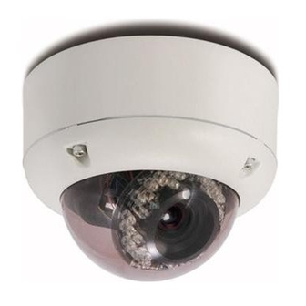
Page 18: Ica-Hm135 H.264 Mega-Pixel 20M Ir Vandal Proof Ip Dome
5. Connect the LAN cable to a switch or hub. When this switch/hub is a PoE device, you can ignore the next step. 6. Connect Power Jack to the bundled power adapter. 7. Done. 2.5 ICA-HM135 H.264 Mega-Pixel 20M IR Vandal Proof IP Dome 2.5.1 ICA-HM135 Package Content IP Camera Unit x 1... - Page 19 Power LED (orange color) This LED is used to indicate whether DC power is on or not. In addition, this LED will be flashing while the network accessing of the IP camera. RS485 & DI/DO MIC in Line out Power Jack RJ-45 Reset Button 2. R S-485: Connect to a local keyboard controller.
-
Page 20: Ica-Hm135 Installation
Restore the device: a. Press the button down continuously. b. Hold the button at least 5 seconds and release it. Then the device has been restored to default settings and reboot again. 4. P ower Jack The input power is DC 12V. 1. ONLY use package power adapter supplied with the internet. - Page 21 2. Set the mounting base onto the wall or ceiling and center it over the mounting hole, using the supplied four retaining screws to secure the main body. 3. Set the proper image by moving the IP camera body and set the focus by turning the lens to the left or right direction.
-
Page 22: Ica-Hm350 H.264 Mega-Pixel 30M Outdoor Ir Internet Camera
6. Connect the LAN cable to a switch or hub. When this switch/hub is a PoE device, you can ignore the next step. 7. Connect DC-Jack to the with the bundle power adapter power source. 8. Done. 2.6 ICA-HM350 H.264 Mega-Pixel 30M Outdoor IR Internet Camera 2.6.1 ICA-HM350 Package Content IP Camera Unit x 1... - Page 23 Power LED (orange color) This LED is used to indicate whether DC power is on or not. In addition, this LED will be flashing while the network accessing of the IP camera. RS485 & DI/DO Video out MIC in Line out Power Jack RJ-45 Reset Button...
-
Page 24: Ica-Hm350 Installation
4. R eset Button This button is used to restore the all factory default settings. Sometimes restarting the device will make the system back to a normal state. However, if the system still got problems after restart, user can restore the factory default settings and install it again. Restore the device: a. -
Page 25: Ica-H610 H.264 Indoor Ptz Internet Camera
2.7 ICA-H610 H.264 Indoor PTZ Internet Camera 2.7.1 ICA-H610 Package Content IP Camera Unit x 1 Power Adapter x 1 Camera Mount Kit x 1 A/V Cable x 1 User’s Manual CD-ROM x 1 Quick Installation Guide x 1 If any of the above items are missing, please contact your dealer immediately. - Page 26 2. L AN LED This LED will be flashing while network accessing via Ethernet. 3. M icrophone The Camera has built-in an internal microphone. This microphone is hidden in the pinhole located on the front panel. Rear View Power Jack Audio/Video LAN Socket Output Jack Factory Default External...
-
Page 27: Ica-H610 Installation
3. E xternal Microphone Connect a microphone to the IP camera. 4. S D Card Slot User can insert a micro SD card into this slot for event recording. 5. R J-45 LAN Socket The LAN socket is a RJ-45 connector for connections to 10/100Base-TX Fast Ethernet cabling. - Page 28 2. Fix the bracket and IP camera to the ceiling using two holly wall anchors and screws. 3. Connect the LAN cable to a switch or hub. When this switch/hub is a PoE device, you can ignore the next step. 4.
-
Page 29: Ivs-H120 H.264 Internet Video Server
2.8 IVS-H120 H.264 Internet Video Server 2.8.1 Package Content Video Server Unit x 1 Power Adapter x 1 User’s Manual CD-ROM x 1 Quick Installation Guide x 1 A/V cable x 1 1. If any of the above items are missing, please contact your dealer immediately. - Page 30 In the LAN socket, there are two LEDs embedded: LAN LED (green color) This LED will be flashing while network accessing via Ethernet. Power LED (orange color) This LED is used to indicate whether DC power is on or not. In addition, this LED will be flashing while the network accessing of the IVS-H120.
-
Page 31: Ivs-H120 Installation
4. 5 V DC Jack The input power is 5V DC. 1. ONLY use package power adapter supplied with the internet. Otherwise, the product may be damaged. 2. Please DON’T plug DC 12V power into the power jack, Note that will damage your IVS-H120. 2.8.3 IVS-H120 Installation 1. -
Page 32: Chapter 3. Camera Windows Utility
Chapter 3. Camera Windows Utility This chapter shows how to quick set up your H.264 IP Camera. The H.264 IP Camera is with the default settings. However to help you find the networked camera quickly the windows utility (PLANET IPWizard II) can search the IP cameras in the network that shall help you to configure some basic setting before you started advanced management and monitoring. - Page 33 View function: If PLANET IPWizard II finds network devices, View button will be available. Please select the device you want to view and click the View button. Furthermore you could double click the left button of mouse to link to the network device by browser. LAN setting: The utility featured with “LAN”...
- Page 34 1. If no IP address is assigned within 30 seconds, the networked device will automatically assign 192.168.0.20. User may now open your web browser, and key in http://192.168.0.20 in the address bar of you web browser to logon IP Camera’s web config- uration page.
-
Page 35: Further Information
Further Information This guide is used to help you startup your IP Camera settings. It is also recommended to check the user manual in CD disk for more details of the system and user configuration. - Page 36 This page is intentionally left blank...