Table of Contents
Advertisement
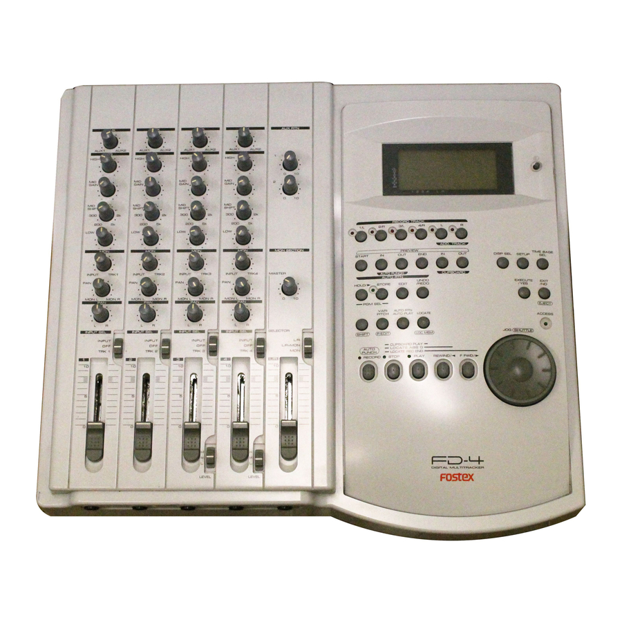
Owner's Manual
Model
Digital Multitracker
AUX
AUX
AUX
AUX
0
0
0
0
AUX1
AUX2
AUX1
AUX2
AUX1
AUX2
AUX1
AUX2
EQ
EQ
EQ
EQ
HIGH
0
HIGH
0
HIGH
0
HIGH
0
-
+
-
+
-
+
-
+
MID
MID
MID
MID
GAIN
0
GAIN
0
GAIN
0
GAIN
0
-
+
-
+
-
+
-
+
MID
MID
MID
MID
SHIFT
SHIFT
SHIFT
SHIFT
900
900
900
900
300
2k
300
2k
300
2k
300
2k
200
5k
200
5k
200
5k
200
5k
LOW
0
LOW
0
LOW
0
LOW
0
-
+
-
+
-
+
-
+
MON
MON
MON
MON
0
0
0
0
INPUT
TRK1
INPUT
TRK2
INPUT
TRK3
INPUT
TRK4
MASTER
PAN
PAN
PAN
PAN
MON L
MON R
MON L
MON R
MON L
MON R
MON L
MON R
PAN
PAN
PAN
PAN
L
R
L
R
L
R
L
R
INPUT SEL
INPUT SEL
INPUT SEL
INPUT SEL
SELECTOR
INPUT
INPUT
INPUT
INPUT
OFF
OFF
OFF
OFF
TRK 1
TRK 2
TRK 3
TRK 4
1
2
3
4
L/R
10
10
10
10
5
5
5
5
0
0
0
0
H
H
M
M
L
L
LEVEL
LEVEL
AUX RTN
1
0
10
2
0
10
RECORD TRACK
1/L
2/R
3/L
4/R
L
R
ADD. TRACK
MON SECTION
PREVIEW
START
IN
OUT
END
IN
OUT
AUTO PUNCH
CLIPBOARD
AUTO RTN
UNDO/
HOLD/
STORE
EDIT
REDO
0
10
PGM SEL
VARI
AUTO RTN
PITCH
AUTO PLAY
LOCATE
SHIFT
P. EDIT
LOC MEM
L/R
L/R+MON
MON
CLIPBOARD PLAY
LOCATE ABS 0
AUTO
PUNCH
LOCATE REC END
RECORD
STOP
PLAY
REWIND
F FWD
10
5
0
DIGITAL MULTITRACKER
TIME BASE
SETUP
DISP SEL
SEL
EXECUTE
EXIT
/YES
/NO
ELECT
ACCESS
JOG
SHUTTLE
Advertisement
Table of Contents

Related Manuals for Fostex FD-4


Summary of Contents for Fostex FD-4
- Page 1 Owner’s Manual Model Digital Multitracker AUX RTN AUX1 AUX2 AUX1 AUX2 AUX1 AUX2 AUX1 AUX2 HIGH HIGH HIGH HIGH GAIN GAIN GAIN GAIN SHIFT SHIFT SHIFT SHIFT MON SECTION INPUT TRK1 INPUT TRK2 INPUT TRK3 INPUT TRK4 MASTER MON L MON R MON L MON R...
-
Page 2: Safety Instructions
Safety Instructions CAUTION RISK OF ELECTRIC SHOCK DO NOT OPEN CAUTION: TO REDUCE THE RISK OF ELECTRIC SHOCK, DO NOT REMOVE COVER (OR BACK). NO USER - SERVICEABLE PARTS INSIDE. REFER SERVICING TO QUALIFIED SERVICE PERSONNEL. "WARNING" "TO REDUCE THE RISK OF FIRE OR ELECTRIC SHOCK, DO NOT EXPOSE THIS APPLIANCE TO RAIN OR MOISTURE."... -
Page 3: Table Of Contents
Real track and Additional track...26 Input monitoring and playback monitoring...26 PAN knob and Stereo bus...27 Basic Application Basic Recording and Playback...28 FD-4 initial settings...28 Recording one sound source to one track...28 Undo/Redo recording...30 Recording onto the additional track...30 Checking the recording sound...31 Basic Multitrack Recording...32... -
Page 4: Introduction
You can set up a synchronization system with a sequencer or a rhythm machine without wasting a track. • You can use the FD-4 as a sync slave machine by sending MTC from a connected device. • The FD-4 supports MTC, MMC, and Fostex System Exclusive Message, which allows for advanced control and high- precision synchronization from external sequencing software. -
Page 5: Recording Preparation
<Note> If the “No Drive !” message and the “Initial..” message flash alter- nately on the display when you turn on the power, the FD-4 cannot recognize the SCSI drive. Check to see whether all connections are made correctly, that the power to the SCSI drive is turned on, and that the cable is not defective. -
Page 6: Formatting A New Disk
Disk Management System-3), which is also used on the Fostex digital master recorder D-160. Therefore, the D-160 can play back data that was recorded in Mastering mode 1 or 2 on the FD-4. However, the D-160 can not play back data recorded in Normal mode. DRIVE SCSI A.PUNCH... -
Page 7: Removing A Disk From The Scsi Drive
The indicated “SYNC OUT” setting ([CLK]) means that clock signals (MIDI clock signal and Song Position Pointer) are output as a sync signal from the FD-4’s MIDI OUT connector to an external MIDI de- vice. You may change this setting, if necessary, when you are using the FD-4 to sync with an external MIDI device. -
Page 8: Formatting The Disk Again
Formatting the disk again If you wish to change the recording mode of a formatted disk or to re-format a used disk, you need to set the FD-4 to SETUP mode and use the [Format ?] menu. In the following procedure, we assume that the power to the FD-4 and the SCSI drive is already turned on. -
Page 9: Names And Functions
Names and Functions Rear panel RECORDER MIDI INSERT INPUT INPUT Control panel AUX1 AUX2 AUX1 AUX2 AUX1 HIGH HIGH HIGH GAIN GAIN GAIN SHIFT SHIFT SHIFT INPUT TRK1 INPUT TRK2 INPUT MON L MON R MON L MON R MON L MON R INPUT SEL INPUT SEL... -
Page 10: Control Panel (Mixer Section)
Names and Functions Control Panel (Mixer Section) AUX1 AUX2 HIGH GAIN SHIFT INPUT TRK1 MON L MON R INPUT SEL INPUT TRK 1 1. Input faders [1-4] These faders allow you to control the input level of signals selected via the INPUT SEL switch [2] (that is, the input signals from the INPUT jacks or the recorder output signals). - Page 11 5. Monitor level control knob [MON (INPUT/TRK)] These knobs are used to select signals sent to monitor sections L and R, and to adjust the level of those signals. The following options are available. “TRK” The recorder output signals are sent to the monitor section.
-
Page 12: Control Panel (Recorder Section)
To cancel this input monitoring status, press the RECORD button again. (This causes the FD-4 to enter playback monitoring mode.) You can also use these select keys to select tracks to edit for Copy &... - Page 13 BAR/BEAT/CLK). The space indication uses MB (Megabyte). (The values are based on mono track recording.) *3 MTC being input from an external MIDI device to the FD-4 appears. If no MTC is input, the display shows “00H 00M 00S 00F.”...
- Page 14 Pressing this button causes the recorder section to play back. Pressing this button while holding down the RECORD button when a track is in READY mode will cause the FD-4 to start recording on the READY track. Pressing only this button during the recording operation will punch-out (cancel) recording.
- Page 15 This mode is effective only when Auto Play mode and Auto Return mode are turned on. The FD-4 will play the part between the AUTO RTN START point and the AUTO RTN END point repeatedly. This mode is also effective only if the AUTO RTN START point and the AUTO RTN END point have already been specified.
- Page 16 [Redo!] appears on the display for a short moment. <Note> The Undo/Redo function is enabled only when the FD-4 is stopped. Refer to pages 30, 31, 33, 46, 48, 50, 58 and 60 for more information on the Undo/Redo function.
- Page 17 Use this key to store the start point of audio data to be copied or moved. When you press this key, the FD-4 displays data currently stored, and you can edit the data. After editing the data, press the STORE key, then press the CLIPBOARD IN/PREVIEW key to store the edited data in this key.
-
Page 18: Front Panel (Input/Output Section)
Names and Functions Front Panel (Input/Output Section) 1.Input jacks [1, 2, 3, 4] (Connector: phone) Connect sound sources, such as musical instruments and microphones, here. Connect a microphone to input jacks 3 and 4, which are equipped with TRIM switches that allow you to switch according to the connected microphone output level. - Page 19 You can also use these jacks as auxiliary inputs. If a connected effect unit has a mono output, connect the output to the L/MONO jack of the FD-4. The right channel will also receive the same signal. Adjust the level of processed signals using AUX RTN knobs 1 and 2.
-
Page 20: Display Section
This section describes display functions along with examples. Display when the power is turned on When you turn the power on to the FD-4 and the connected external SCSI drive (with a formatted removable disk inserted), the display shows the [Initial...] message, then... -
Page 21: Preset Display
A.PUNCH BAR, , CLK (*) When the FD-4 has the optional 2.5 inch internal IDE hard disk installed, and an external SCSI drive is not connected, [IDE] will be lit. However, even though an internal hard disk has been installed, if the external SCSI drive is connected, the SCSI drive will have priority and [SCSI] will be lit. -
Page 22: The Remain Display
The figure displayed here applies to all of the real tracks and additional tracks. 44.1kHz For details on the REMAIN display, please refer to “FD-4 recording type and the REMAIN indicator” in “Before starting” on page 25. DRIVE SCSI A.PUNCH... -
Page 23: Warning Messages
<Unformat !> message An unformatted or crashed SCSI disk. After a few seconds of this display, the FD-4 automatically enters the SETUP mode [Format ?] menu. Action to take: Press the EXECUTE/YES key while pressing the RECORD button. -
Page 24: Before Starting
The FD-4 offers three types of Time Base: ABS (Absolute type), MTC (MIDI time code), and BAR/BEAT/CLK (bar/beat/clock). ABS indicates an absolute time on the disk. MTC indicates a relative time that is obtained by adding a certain value (MTC offset value) to the ABS value. -
Page 25: Recording Method And Remain Indicator
FD-4 will not access the disk. However, MTC will be output when you try to play this area. On the FD-4, the top of the disk is called “ABS 0” and the recording end point is called “REC END.” REMAIN indicator... -
Page 26: Real Track And Additional Track
Before Starting Real track and Additional track The FD-4 features four Real tracks (1–4) and two Additional tracks (L and R), for a total of six tracks. Real tracks are used to record sound sources in real-time. Additional tracks are used to temporarily store the sound recorded in the Real tracks. -
Page 27: Pan Knob And Stereo Bus
PAN knobs and stereo bus The FD-4 features a four-channel mixer function that en- ables you to mix four sound sources into a stereo mix. Since the mixer functions and signal flow are not visible, the following diagram will help you understand them. -
Page 28: Basic Application
* Initialize the FD-4 before recording. Setting the disk 1. Turn on the power to the FD-4 and the SCSI drive, and insert the disk. The FD-4 displays [Normal] (recording mode), then displays the start of ABS time (ABS 00M 00S 00F). -
Page 29: Starting Recording
4 5 6 Setting the switch and knob 1. Set the channel 1 INPUT SEL switch to [INPUT]. The electric guitar signal is routed to the input channel 1 fader. If you connect the instrument to another input jack, set the INPUT SEL switch of the corresponding channel to [INPUT]. -
Page 30: Undo/Redo Recording
• Press the UNDO/REDO key again to restore the conditions that existed after the recording. <Note> The Undo/Redo is effective only in the stop mode of the FD-4. Undo/Redo will not effective if the following is executed prior to carrying out UNDO/REDO. -
Page 31: Checking The Recording Sound
<Note> The Undo/Redo is effective only in the stop mode of the FD-4, the same as when recording onto a real track.. Undo/Redo will not effective if the following is executed prior to carrying out UNDO/REDO. -
Page 32: Basic Multitrack Recording
Refer to “Using the Program Change function” on page 37 for more information on changing the Programs. * Initialize the FD-4. Connecting a sound source 1. Connect the electric bass to input jack 1. -
Page 33: Listening To The Overdubbed Sound
• Press the UNDO/REDO key again to restore the conditions that existed after the overdubbing. <Note> The Undo/Redo function is effective only when the FD-4 is stopped. The Undo/Redo is ineffective if you perform one of the following operations after you finish recording. -
Page 34: Mixdown
Track 2 Track 1 To output signals for mixdown (stereo bus L/R output), the FD-4 is equipped with DATA OUT jacks that output digital signals (S/P DIF format), as well as the STEREO OUT L/R jacks for analog output. This makes it possible to perform high-quality digital mixdown without tonal deterioration onto an external DAT machine with optical inputs. - Page 35 Adjust the input level on the master recorder so that its level meters indicate almost the same level as the FD-4’s level meters L/R. 13. Press the FD-4’s PLAY button to play the Program from the beginning. Operate the master faders L/R to fade the mixdown sound in and out.
-
Page 36: Handling Programs
REWIND F FWD DIGITAL MULTITRACKER 1. Turn on the power to the FD-4 and a connected SCSI drive. 2. Insert a formatted disk into the SCSI drive. The FD-4 displays [Initial..], [(SCSI drive name and ID number)], [(Recording mode, such as [Normal])], then the top of ABS Time Base (ABS 0). -
Page 37: Using The Program Change Function
If multiple Programs exist on the disk, you need to select a Program to record, play, or edit. This section describes how to select a Program. <Note> You cannot use the Program Change function when the FD-4 is in SETUP mode. RECORD TRACK ADD. TRACK... -
Page 38: Deleting A Program
[SURE ?] flashes. To cancel the delete operation, press the EXIT/NO key while [SURE ?] is flashing. Each time you press the button or key, the FD-4 will return to a higher level in the hierarchy, and finally exit SETUP mode. -
Page 39: Editing A Program Title
<Note> You can edit the title of the selected Program before you select SETUP mode. You cannot select a Program after the FD-4 enters SETUP mode. Be sure to select the desired Program using the steps explained in the “Using the Program Change function”... -
Page 40: Special Application
<Note> The Vari Pitch function is automatically turned off and the [VARI PITCH] indicator is turned off under the following conditions: • You have turned on the power to the FD-4. (The pitch data will 44.1kHz be reset to 0.0%.) •... -
Page 41: Recording To A Metronome Sound
For example, record the acoustic guitar using a microphone to track 2 while using a compressor/limiter. • Initialize the FD-4 before the operation. • If multiple Programs exist, first select the desired Program. Connecting a sound source and a effect unit... - Page 42 2. Start playback from the beginning of the Program. Even if the selected Program does not have any recorded data, track 4 outputs the metronome sound and the FD-4 counts time. 3. Turn the MON knob of channel 4 MON mix section toward TRK, and turn the MASTER knob in the monitor section gradually.
-
Page 43: Punch In/Out Recording
In this example, use the Preview function to fine-tune the point while previewing. 1. While the FD-4 is stopped, hold down the SHIFT key and press the memory key. Pressing the AUTO PUNCH IN key enables you to listen to the sound at the AUTO PUNCH IN point (“previewing the... - Page 44 <Tips for rehearsal> Set the preroll value while referring to the “Changing the Initial Set- tings (SETUP Mode)” chapter. In this way, the FD-4 can locate a point that precedes the Auto Punch In point by the specified preroll value. This enables you to start playback slightly before the Punch In point.
- Page 45 AUTO RTN START point. <Note> If the FD-4 display [Over] when you turn on Auto Punch mode, the disk does not have enough free space for Auto Punch In/Out. You need to erase part of the Program data, then try again.
-
Page 46: Manual Punch In/Out
Press the UNDO/REDO key again to restore the conditions that existed after the recording. Follow the notes below: <Note-1> The Undo/Redo function is effective only when the FD-4 is stopped. <Note-2> The Undo/Redo is not effective if you perform one of the following operations after you finish recording: •... - Page 47 This will help you concentrate on your performance or check the recording level easily (especially since Manual Punch In/Out in- volves operating the foot switch operation as well as the FD-4). (See <Hint-2> in the “Rehearsing Auto Punch In/Out recording” for more information.)
- Page 48 This is a functional feature of FD-4 and not a malfunction. <Hint> You can use the PLAY button and the RECORD button, instead of using the foot switch.
-
Page 49: Ping-Pong Recording
Sound source C Sound source B TRK 2 TRK 1 Sound source A • Initialize the FD-4. • If multiple Programs exist, select the desired Program first. 3. Record D and E on tracks 1 and 2. Sound source A,B,C... - Page 50 1–3 and overdub other sound sources. In this way, you can record numerous sound sources with a limited number of tracks. You can also use the Additional tracks of the FD-4 for ping- pong recording (excluding disks formatted in Mastering mode 2).
-
Page 51: Ping-Pong Recording To Additional Tracks
You cannot play back data recorded on Additional tracks. To play back the data, move it to Real tracks 1–2 or 3–4. • Initialize the FD-4 before you start the operation. • If multiple Programs exist, select the desired Program first. -
Page 52: Digital Recording
44.1kHz. Connecting an external digital device 1. Connect the DATA IN jack of the FD-4 with the OPTICAL OUT jack of an external digital device using an optical cable. If the digital device has only the COAXIAL (RCA pin) jack as a digital output, use a Fostex COP-1 (an optional optical/coaxial converter). -
Page 53: Digital Recording To An External Device
Digital recording to an external device This section explains how to record digital data from the FD-4 to an external digital device, such as an MD, DAT, or CD-R. You can select any pair combination from Real tracks 1–4 and S-T (STEREO OUT L/R output in the mixer section) for digital output L and R. -
Page 54: Digital Mixdown
Effect unit 2 4, 8 Connecting an external digital device 1. Connect the DATA OUT jack of the FD-4 with the OPTICAL IN jack of an external digital device using an optical cable. Assigning output tracks 2. Use the “Setting digital output tracks” menu in SETUP mode... -
Page 55: How To Use The Recorder In Jack
Eight channels of digital mixdown In this method, the RECORDER IN (L, R) jacks of the FD-4 are directly connected to the MON OUT (L, R) jacks and the moni- tor SELECTOR switched to [L/R+MON]. Then, the monitor bus... -
Page 56: Editing Tracks
(this is called [Move Clip] on the FD-4), and paste it to a destination track. The difference from Copy & Paste is that the data on the source track and the clipboard will be erased when you paste the data to the destina- tion. -
Page 57: Storing The Edit Points
The copy or move operation will complete immediately. The display briefly indicates [COMPLETED !], then flashes the [Copy Paste] message (or the [Move Paste] message). The FD-4 enters standby mode for the paste operation. The LEDs of the selected RECORD TRACK select keys continue to flash. -
Page 58: Erase
• To restore the pasted data after you undo the paste operation, press the UNDO/REDO key again. <Note> The Undo/Redo function is effective only when the FD-4 is stopped. <Note> If you perform one of the following operations after you use the Copy &... -
Page 59: Executing Erase
<Note> If all Real tracks contain data as shown below, erasing data on tracks 1 and 2 will not affect the position of REC END. AUTO PUNCH IN point Real track ABS 0 Real track ABS 0 On the other hand, if all Real tracks contain data as shown below, erasing data on tracks 3 and 4 will move up REC END to the end point of tracks 1 and 2. -
Page 60: Track Exchange
• To restore the data after you undo the Erase operation, press the UNDO/REDO key again. When you press the UNDO/REDO key, the FD-4 will undo or redo the operation immediately, and display [Undo!] or [Redo !] and [COM- PLETED !]. -
Page 61: Executing Track Exchange
1 and 4. <Note> If you select the same tracks for swapping mono track data, the setting is ignored. The FD-4 will indicate [Select Err] for a short mo- ment, then return to the previous display. 4. Press the EXECUTE/YES key. -
Page 62: Cue & Review Function
<Note> When the beginning of the disk is reached during the review opera- tion, the FD-4 starts normal playback, even if you are still holding down the SHIFT key. When the end of the disk (ABS time: 23H 59M 59S) is reached during the cue operation, the FD-4 stops and the PLAY button LED flashes. -
Page 63: Storing A Locate Point (Edit Point)
In addition to the memory keys, you can store data in the LOCATE key in real-time. The LOCATE key always stores the point most recently located by the FD-4. That is, data in the LOCATE key is overwritten by new data each time the FD-4 locates a point. -
Page 64: Editing And Storing Locate Data
You can recall data stored in the memory key, edit it, and store it. again 1. While the FD-4 is stopped, press the memory key that stores the data you wish to edit. The stored data appears on the display and the FD-4 enters data edit mode. -
Page 65: Editing The Data Stored In The Locate Key
The last located point stored in the LOCATE key appears on the display and the FD-4 enters data edit mode. If no data is stored (that is, if the FD-4 has not located any point since the power was turned on), 00H 00M 00S 00F 00SF appears and “00”... -
Page 66: Locate Function
This function is effective within 24 ABS hours. Therefore, if playback continues over the recording end point, the FD-4 will still continue count- ing the time. Also, when the FD-4 locates ABS REC END, it will continue counting the time from the recording end point. (However, the FD-4 does not access the disk after reaching the recording end point.) -
Page 67: Auto Return
• You can set a preroll time in the [Preroll ?] menu in SETUP mode so that the FD-4 will start playback preroll time before the locate point. You can set the preroll time from 0 to 10 seconds. Refer to the chapter “Changing the Initial Settings (SETUP Mode)”... -
Page 68: Auto Repeat
• You can set a preroll time in the [Preroll ?] menu in SETUP mode so that the FD-4 will start playback preroll time before the locate point. You can set the preroll time from 0 to 10 seconds. Refer to the chapter “Changing the Initial Settings (SETUP Mode)”... -
Page 69: Preview Function Executing The Preview Function
<Display indication during the Preview operation> The FD-4 repeats playback the “rise sound” at the locate point (edit point). As shown in the diagram, one-second of data prior to the locate point is muted during playback. The mute is off (fade in) at the locate point and the sound is played back for one second. -
Page 70: Trimming The Sound While Previewing
Preview Function The FD-4 repeats playback of the “fall sound” at the locate point (edit point). As shown in the diagram, one-second of data prior to the locate point is played back, then muted (fade out) at the locate point. -
Page 71: Midi Synchronization
SCSI IN/OUT MIDI sequencer 1. Connect the MIDI OUT jack of the FD-4 to the MIDI IN jack of the MIDI sequencer. 2. Set the MIDI sequencer to “MIDI clock slave” mode, and connect the MIDI sound source (played automatically) to the input jack of the FD-4. -
Page 72: Mtc Sync/Machine Control System
MMC (MIDI Machine Control) and controlled by MTC (MIDI time code) output from the FD-4. The FD-4 adds a given offset value to the ABS time on the disk and outputs the information as MTC of a given frame rate. -
Page 73: Setting The Device Id Number
MIDI <Please read this> About MMC REC Out function If you use the MMC REC Out function, operating the FD-4 will cause the MIDI OUT connector to output the MMC command that corresponds to the operation. For example, pressing the PLAY button while pressing the RECORD button will output the MMC REC command from the MIDI OUT connec- tor. -
Page 74: Sync System In Slave Mode
<Note> The FD-4 can chase and lock to MTC only when the speed variation of MTC sent from the master device (computer) is within +/-5.6%. Within this range, the FD-4 will use the Vari Pitch function internally to chase MTC. - Page 75 About the option “Vari” in the “Setting the Slave type” in SETUP mode: If the FD-4 chases and locks to only an incoming MTC, Vari Pitch is applied all the time. Under this condition, if the FD-4 outputs digital signals to a connected digital device, the device may not be able to accommodate the FD-4’s speed variation (MTC speed variation of...
-
Page 76: Saving And Loading Song Data
In this case, set the sync mode of the DAT to INTERNAL, or disconnect the optical cable from the DATA OUT of the FD-4 before loading data. This type of problem will not occur during the save operation since the DATA IN connector of the FD-4 is not effective. -
Page 77: Saving Song Data
• You cannot load data with a different sampling rate. For example, if you save data recorded in Normal mode to a DAT tape, then load it back to the FD-4, you will be unable to load the data if the load destination disk has been formatted in Mastering mode 1 or 2 (sampling rate: 44.1kHz), and vice versa. - Page 78 The pilot signal (beep sound), tracks 1 and 2, 3 and 4, and 5 and 6 will be saved to the DAT tape sequentially, in this order. During the save operation, the level meters 1 and 2, and L and R on the FD-4 indicate the output levels. SETUP DRIVE SCSI A.PUNCH...
-
Page 79: Loading Song Data
Loading song data You can load the data from DAT to the SCSI disk of the FD-4. Preparing a DAT machine • Turn on the power to the DAT machine, and insert the tape that includes the data you wish to load. - Page 80 [TRK 2] respectively • Turning the MASTER knob in the monitor section When the save operation is complete, [COMPLETED !] lights up on the display, and FD-4 stops. Stop playing the DAT machine. 9. Press the STOP button or the EXIT/NO key.
-
Page 81: Changing The Initial Settings (Setup Mode)
(Refer to the next page for more information.) To exit SETUP mode, press the STOP button or the EXIT/NO key. Each time you press one of these keys, the FD-4 returns to the previous hier- archy level of the menu, and finally exits SETUP mode. -
Page 82: Setting A Time Signature
To cancel the setting operation, or to exit SETUP mode after storing data, press the STOP button or the EXIT/NO key. Each time you press one of these keys, the FD-4 returns to the previous hierarchy SETUP level of the menu, and finally exits SETUP mode. -
Page 83: Setting A Tempo
12th measure. Time signature and tempo settings make a Tempo Map, which is used by the FD-4 to manage the song using the BAR/BEAT/CLK Time Base, and enable the Metronome func- tion. Tempo settings as well as time signature settings are required when you wish to output MIDI clock and Song Position Pointer to an external sequencer. - Page 84 Changing the Initial setting (SETUP mode) 4. Press the HOLD/> key, the REWIND button, or the F FWD button to move the flashing cursor to the desired edit location, and use the JOG dial to enter the bar/beat/tempo information to be stored. Pressing the HOLD/>...
-
Page 85: Setting The Metronome Function
To cancel the setting operation, or to restore the setting obtained prior to the EXECUTE/YES key press, press the STOP button or the EXIT/NO key. Each time you press one of these keys, the FD-4 returns to the previous hierarchy level of the menu, and finally exits SETUP mode and displays the previous Time Base. -
Page 86: Setting Midi Sync Output Signal
The “Setting MIDI sync output signal” menu enables you to select the type of MIDI sync signals output from the MIDI OUT connector on the rear panel of the FD-4 to an external MIDI device. The options are MIDI clock & Song Position Pointer, or MTC (MIDI time code). -
Page 87: Setting An Mtc Frame Rate
To cancel the operation, or to restore the setting obtained prior to the EXECUTE/YES key press, press the STOP button or the EXIT/ NO key. Each time you press one of these keys, the FD-4 returns to the previous hierarchy level of the menu, and finally exits SETUP mode and displays the previous Time Base. -
Page 88: Setting Offset Mode
To cancel the operation, or to restore the setting obtained prior to the EXECUTE/YES key press, press the STOP button or the EXIT/NO key. Each time you press one of these keys, the FD-4 returns to the previous hierarchy level of the menu, and finally exits SETUP mode and displays the previous Time Base. -
Page 89: Setting The Slave Type
To cancel the operation, or to restore the setting obtained prior to the EXECUTE/YES key press, press the STOP button or the EXIT/ NO key. Each time you press one of these keys, the FD-4 returns to the previous hierarchy level of the menu, and finally exits SETUP mode and displays the previous Time Base. -
Page 90: Setting The Record Protection Function
Changing the Initial setting (SETUP mode) <Note> • You need to input MTC from an external device to the FD-4 with any Slave type (external sync signal). • The FD-4 re-chase window is fixed to ten frames. That is, if an... -
Page 91: Setting Digital Input Tracks
To cancel the operation, or to restore the setting obtained prior to the EXECUTE/YES key press, press the STOP button or the EXIT/ NO key. Each time you press one of these keys, the FD-4 returns to the previous hierarchy level of the menu, and finally exits SETUP mode and displays the previous Time Base. -
Page 92: Setting Digital Output Tracks
To cancel the operation, or to restore the setting obtained prior to the EXECUTE/YES key press, press the STOP button or the EXIT/ NO key. Each time you press one of these keys, the FD-4 returns to the previous hierarchy level of the menu, and finally exits SETUP mode and displays the previous Time Base. -
Page 93: Setting The Midi Device Number
To cancel the operation, or to restore the setting obtained prior to the EXECUTE/YES key press, press the STOP button or the EXIT/ NO key. Each time you press one of these keys, the FD-4 returns to the previous hierarchy level of the menu, and finally exits SETUP mode and displays the previous Time Base. -
Page 94: Midi Implementation Chart
******************************* (rem. 1) (rem. 2) (rem. 3) rem. 1: MMC (Device ID=00~99, 127), MTC, Identity reply, FOSTEX Exclusive rem. 2: MMC (Device ID=00~99, 127), MTC, Inquiry, FOSTEX Exclusive rem. 3: START, STOP, CONTINUE Mode 2: OMNI ON, MONO Mode 4: OMNI OFF, MONO Date: Version: V1.00... -
Page 95: Mmc Command List/Inquiry Message List
IDENTITY REPLY: F0, 7E, <channel>, 06, 02, 51, 01, 00, 0F, 00, 01, 00, 7F, 7F, F7 51: Fostex ID 01, 00: Device family code 0F, 00: Device family number FD-4 01, 00, 7F, 7F: Software version MIDI Implementation Chart/MMC List/Maintenance/Specifications... -
Page 96: Maintenance/Specifications
(SCSI-2, asymmetrical transfer) : Internal 2.5 inch hard disk (E- IDE type) : Connectable SCSI device: One : FDMS-3* <Recording Format> (* Fostex Disk Management System-3) <Recording Mode> Normal Mode : 4 Real track + 2 Additional track (Sampling Rate: 32kHz/... -
Page 97: Block Diagram
* 32kHz/16-bit linear (Normal mode), Corresponds to DAT 32kHz/SP mode. * 44.1kHz/16-bit linear (Mastering mode 1, 2) : FDIO-1* <Save/Load> (*) Fostex Data Input /Output-1) <Recording Track> : 2 tracks (Analog x 2, or Digital x 2) : 4 tracks <Playback Track>... -
Page 98: Declaration Of Ec Directive
* In the electrical fast transient / burst requirements, radiated electromagnetic field requirements and static electricity discharging envi- ronment, this could be affected by generation of noise in some cases. FOSTEX DISTRIBUTORS LIST IN EUROPE * Including non - EU countries. * underlined: contracted distributors (as of November, 1997) <AUSTRIA>... - Page 99 INDEX ABS time...24 Additional track...26, Analog recording...28 Auto punch in/out...43 Auto play...66 Auto return...67 Auto repeat...68 Backup...76 Bar/beat resolution setting...92 Clipboard play...14, 57 Copy paste...56 Cue/review function...62 Can’t Rec display...23 Display...20 Disk remain...22, 25 Disk error...23 Default setting...28 Deleting program...38 Direct locate...66 Digital recording...52 Digital mixdown...54...
- Page 100 FOSTEX CORPORATION 3-2-35, Musashino, Akishima-shi, Tokyo, Japan 196 -0021 FOSTEX CORPORATION OF AMERICA 15431, Blackburn Ave., Norwalk, CA 90650, U. S. A. C PRINTED IN JAPAN APR. 1998 8288 414 100 FX...