Table of Contents
Advertisement
Advertisement
Table of Contents

Related Manuals for Supermicro X7DB8-X


Summary of Contents for Supermicro X7DB8-X
- Page 1 UPER X7DB8-X X7DBE-X USER’S MANUAL Revision 1.1a...
- Page 2 Please Note: For the most up-to-date version of this manual, please see our web site at www.supermicro.com. SUPER MICRO COMPUTER reserves the right to make changes to the product described in this manual at any time and without notice.
-
Page 3: Manual Organization
Intel Xeon 64-bit dual core processors at a front side bus speed of 1333/1066/667 MHz. With dual Xeon 64-bit dual core processors, the 5000P chipset, and eight DDR2 FBD 667/533 memory modules built-in, the X7DB8-X/X7DBE-X offers substantial functionality and performance enhancements to the motherboards based on the dual core NetBurst microarchitecture while remaining compatible with the 32-bit based software. -
Page 4: Table Of Contents
Conventions Used in the Manual ... iii Chapter 1: Introduction Overview ... 1-1 Checklist ... 1-1 Contacting Supermicro ... 1-2 X7DB8-X/X7DBE-X Image ... 1-3 X7DB8-X/X7DBE-X Layout ... 1-4 Quick Reference ... 1-5 Motherboard Features ... 1-6 Intel 5000P Chipset: System Block Diagram ... 1-8 Chipset Overview ... - Page 5 Reset Button ... 2-13 Power Button ... 2-13 2-5 Connecting Cables ... 2-14 ATX Power Connector ... 2-14 Processor Power Connector ... 2-14 Universal Serial Bus ... 2-15 Chassis Intrusion ... 2-15 Fan Headers ... 2-16 Keylock ... 2-16 ATX PS/2 Keyboard and Mouse Ports ... 2-17 Serial Ports ...
- Page 6 X7DB8-X/X7DBE-X User's Manual SIMLP IPMI Slot ... 2-32 Ultra 320 SCSI Connectors ... 2-33 Chapter 3: Troubleshooting Troubleshooting Procedures ... 3-1 Before Power On ... 3-1 No Power ... 3-1 No Video ... 3-1 Memory Errors ... 3-1 Losing the System’s Setup Confi guration ... 3-1 Technical Support Procedures ...
-
Page 7: Chapter 1: Introduction
Checklist Congratulations on purchasing your computer motherboard from an acknowledged leader in the industry. Supermicro boards are designed with the utmost attention to detail to provide you with the highest standards in quality and performance. Check that the following items have all been included with your motherboard. If anything listed here is damaged or missing, contact your retailer. -
Page 8: Contacting Supermicro
X7DB8-X/X7DBE-X User's Manual Contacting Super Micro Headquarters Address: Super Micro Computer, Inc. 980 Rock Ave. San Jose, CA 95131 U.S.A. Tel: +1 (408) 503-8000 Fax: +1 (408) 503-8008 Email: marketing@supermicro.com (General Information) support@supermicro.com (Technical Support) Web Site: www.supermicro.com Europe Address: Super Micro Computer B.V. -
Page 9: X7Db8-X/X7Dbe-X Image
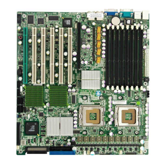
Chapter 1: Introduction Figure 1-1. X7DB8-X/X7DBE-X Image *Note: The drawings and pictures shown in this manual were based on the latest PCB Revision available at the time of publishing of the manual. The motherboard you’ve received may or may not look exactly the same as the... -
Page 10: X7Db8-X/X7Dbe-X Layout
5. When LE1 is on, make sure to disconnect the power supply before removing or installing components. 6. For the ZCR card to function properly, be sure to install it in the green slot. (Green Slot is available for the X7DB8-X only.) 7. Slot 1 supports up to 100 MHz. SMBPS JP3... -
Page 11: Quick Reference
Quick Reference ( X7DB8-X/X7DBE-X) Jumper Description J27, J28 C Bus to PCI-X/PCI-E Slots 3rd PWR Failure Detect JBT1 CMOS Clear JPA1 SCSI Controller Enable JPA2, JPA3 SCSI CHA(JPA2),CHB(JPA3)Term.En Off (Enabled) (*Note) JPG1 VGA Enable JPL1/ JPL2 GLAN1/GLAN2 Enable Watch Dog... -
Page 12: Motherboard Features
Expansion Slots • Three PCI-X 133 MHz slots (*Slots 2/3/6) • Three PCI-X 100 MHz slots (*two PCI-X-100 MHz slots: Slots 4/5, one PCI-X- 100 MHz w/ZCR slot: Slot 1) (*ZCR is available for the X7DB8-X only.) BIOS ® • 8 Mb Phoenix Flash ROM •... - Page 13 • ACPI/ACPM Power Management • Keyboard Wakeup from Soft-off Onboard I/O • Adaptec 7902 dual channel Ultra 320 SCSI with ZCR option (*X7DB8-X only) • Six SATA2 ports (supporting RAID0, 1, 10 and 5) • One SIMLP IPMI socket • Intel 82563 Gigabit Ethernet controller supporting two Giga-bit LAN ports •...
- Page 14 X7DB8-X/X7DBE-X User's Manual PROCESSOR#2 ISL6307 1067/1333 MT/S PCI-EX8 5000P PORT #4,5 PORT #6,7 PCI-E X8 SCSI PORT #2,3 PCI-X100 7902 PCI-X133 PORT PCI-E X4 PORT spare, For IPMI later PCI-E X8 PORT spare, For SAS later #1,2 (PCI-E based) ESB2...
-
Page 15: Chipset Overview
Chapter 1: Introduction Chipset Overview Built upon the functionality and the capability of the 5000P chipset, the X7DB8-X/ X7DBE-X motherboard provides the performance and feature set required for dual processor-based servers with confi guration options optimized for communications, presentation, storage, computation or database applications. The 5000P chipset supports single or dual Xeon 64-bit dual core processor(s) with front side bus speeds of up to 1.333 GHz. -
Page 16: Special Features
Advanced BIOS Setup section to change this setting. (*Default: Last State) PC Health Monitoring This section describes the PC health monitoring features of the X7DB8-X/X7DBE- X. All have an onboard System Hardware Monitor chip that supports PC health monitoring. -
Page 17: Acpi Features
CPU Fan Auto-Off in Sleep Mode The CPU fan activates when the power is turned on. It continues to operate when the system enters Standby mode. When in sleep mode, the CPU will not run at full power, thereby generating less heat. CPU Overheat LED and Control This feature is available when the user enables the CPU overheat warning function in the BIOS. -
Page 18: Power Supply
It is even more important for processors that have high CPU clock rates. The X7DB8-X/X7DBE-X can only accommodate 24-pin ATX power supplies. Al- though most power supplies generally meet the specifi cations required by the CPU, some are inadequate. In addition, the 12V 4-pin power supply - is also required to ensure adequate power supply to the system. -
Page 19: Super I/O
Chapter 1: Introduction NOTE: The + 12V 8-pin Aux. Power Connector is also required to support Intel 64-bit CPUs. Failure to provide this extra power will result in CPU PWR Failure. See Section 2-5 for details on connecting the power supply. It is strongly recommended that you use a high quality power supply that meets ATX power supply Specifi... - Page 20 X7DB8-X/X7DBE-X User's Manual Notes 1-14...
-
Page 21: Chapter 2: Installation
Chapter 2 Installation Static-Sensitive Devices Electric-Static-Discharge (ESD) can damage electronic com ponents. To prevent damage to your system board, it is important to handle it very carefully. The following measures are generally suffi cient to protect your equipment from ESD. Precautions •... -
Page 22: Processor And Heatsink Fan Installation
X7DB8-X/X7DBE-X User's Manual Processor and Heatsink Fan Installation When handling the processor package, avoid placing direct pressure on the label area of the fan. (*Notes: 1. Always connect the power cord last and always remove it before adding, removing or changing any hardware components. Make sure that you install the processor into the CPU socket before you install the CPU heatsink. - Page 23 3. Use your thumb and your index fi nger to hold the CPU at the North Center Edge and the South Center Edge of the CPU. 4. Align CPU Pin1 (the CPU corner marked with a triangle) against the socket corner that is marked with a triangle cutout.
- Page 24 X7DB8-X/X7DBE-X User's Manual Installation of the Heatsink CEK Heatsink Installation 1. Do not apply any thermal grease to the heatsink or the CPU die-the required amount has already been applied. 2. Place the heatsink on top of the CPU so that the four mounting holes are aligned with those on the retention mechanism.
- Page 25 CPU and the heatsink. Mounting the Motherboard in the Chassis All motherboards have standard mounting holes to fi t different types of chas- sis. Make sure that the locations of all the mounting holes for both motherboard and chassis match. Make sure that the metal standoffs click in or are screwed in tightly.
-
Page 26: Installing Dimms
Repeat for all modules (see step 1 above). Memory Support The X7DB8-X/X7DBE-X supports up to 16 GB (32 GB) fully buffered (FBD) ECC DDR2 667/533 in 8 DIMMs. Populating DIMM modules with pairs of memory modules of the same size and same type will result in Interleaved Memory which will increase memory performance. - Page 27 Possible System Memory Allocation & Availability System Device Size Firmware Hub fl ash memory (System 1 MB BIOS) Local APIC 4 KB Area Reserved for the chipset 2 MB I/O APIC (4 Kbytes) 4 KB PCI Enumeration Area 1 256 MB PCI Express (256 MB) 256 MB PCI Enumeration Area 2 (if needed)
-
Page 28: Back Panel Connectors/Io Ports
X7DB8-X/X7DBE-X User's Manual Control Panel Connectors/IO Ports The I/O ports are color coded in conformance with the PC 99 specifi cation. See Figure 2-3 below for the colors and locations of the various I/O ports. A. Back Panel Connectors/IO Ports Figure 2-3. -
Page 29: Front Control Panel
These connectors are designed specifi - cally for use with Supermicro server chassis. See Figure 2-4 for the descriptions of the various control panel buttons and LED indicators. Refer to the following section for descriptions and pin defi... -
Page 30: Front Control Panel Pin Defi Nitions
X7DB8-X/X7DBE-X User's Manual C. Front Control Panel Pin Defi nitions NMI Button The non-maskable interrupt button header is located on pins 19 and 20 of JF1. Refer to the table on the right for pin defi nitions. Power LED The Power LED connection is located on pins 15 and 16 of JF1. -
Page 31: Hdd Led
HDD LED The HDD LED connection is located on pins 13 and 14 of JF1. Attach the hard drive LED cable here to display disk activity (for any hard drives on the system, including SAS, Serial ATA and IDE). See the table on the right for pin defi... -
Page 32: Overheat/Fan Fail Led
X7DB8-X/X7DBE-X User's Manual Overheat/Fan Fail LED (OH) Connect an LED to the OH/Fan Fail connection on pins 7 and 8 of JF1 to provide a warning in the event of chassis overheating or fan failure. Refer to the table on the right for pin defi... -
Page 33: Reset Button
Reset Button The Reset Button connection is located on pins 3 and 4 of JF1. Attach it to the hardware reset switch on the computer case. Refer to the table on the right for pin defi nitions. Power Button The Power Button connection is located on pins 1 and 2 of JF1. -
Page 34: Connecting Cables
X7DB8-X/X7DBE-X User's Manual Connecting Cables ATX Power Connector There are a 24-pin main power sup- ply connector(JPW1) and an 8-pin CPU PWR connector (JPW3) on the motherboard. These power connec- tors meet the SSI EPS 12V specifi ca- tion. The 4-pin 12V PWR supply is required to provide adequate power to the system. -
Page 35: Universal Serial Bus
Universal Serial Bus (USB) There are fi ve USB 2.0 (Universal Serial Bus) ports/headers on the motherboard. Two of them are Back Panel USB ports (USB#0/1:JUSB1), and the other three are Front Panel USB headers (USB#2/3:JUSB2, USB#4: JUSB3). See the tables on the right for pin defi... -
Page 36: Fan Headers
X7DB8-X/X7DBE-X User's Manual Fan Headers The X7DB8-X/X7DBE-X has six chassis/sys- tem fan headers (Fan1 to Fan6) and two CPU Fans (Fans 7/8). (*Note: Fan1 to Fan4 are 3-pin fans, and Fan5 to Fan8 are 4-pin fans. However, Pins 1-3 of 4-pin fan headers are backward compatible with the traditional 3-pin fans.) See the table on the right for pin defi... -
Page 37: Atx Ps/2 Keyboard And Mouse Ports
ATX PS/2 Keyboard and PS/2 Mouse Ports The ATX PS/2 keyboard and the PS/2 mouse are located at JKM1. See the table on the right for pin defi nitions. (The mouse port is above the key- board port. See the table on the right for pin defi... -
Page 38: Wake-On-Ring
X7DB8-X/X7DBE-X User's Manual Wake-On-Ring The Wake-On-Ring header is des- ignated JWOR1.This feature allows your computer to be awakened by an incoming call to the modem when the system is in the suspend state. See the table on the right for pin defi ni- tions. -
Page 39: Glan (Ethernet Ports)
GLAN 1/2 (Giga-bit Ethernet Ports) Two G-bit Ethernet ports are desig- nated JLAN1 and JLAN2 on the IO backplane. This port accepts RJ45 type cables. Power LED/Speaker On the JD1 header, pins 1-3 are for a power LED and pins 4-7 are for the speaker. -
Page 40: Power Fault
X7DB8-X/X7DBE-X User's Manual Power Fault (PWR Supply Failure) Connect a cable from your power supply to the Power Fail (PSF) header (JP3) to provide a warning in the event of a power supply failure. This warning signal is passed through the PWR_LED pin to indicate of a power failure on the chassis. -
Page 41: Overheat Led/Fan Fail
Overheat LED/Fan Fail (JOH1) The JOH1 header is used to connect an LED to provide warning of chassis overheating. This LED will blink to in- dicate a fan failure. Refer to the table on right for pin defi nitions. A System Management Bus header is located at J18. -
Page 42: Vga Connector
X7DB8-X/X7DBE-X User's Manual Power SMB (I C) Connector Power SMB (I C) Connector (J17) monitors the status of PWR Supply, Fan and system temperature. See the table on the right for pin defi nitions. VGA Connector A VGA connector (J15) is located next to the COM1 port on the IO backplane. -
Page 43: Sgpio Headers
SGPIO Headers There are two SGPIO (Serial General Purpose Input/Output) headers (J29, J30) located on the motherboard. These headers support serial link interfaces for the onboard SATA and SAS connectors. See the table on the right for pin defi nitions. Refer to the board layout below for the location. -
Page 44: Jumper Settings
X7DB8-X/X7DBE-X User's Manual Jumper Settings Explanation of Jumpers To modify the operation of the motherboard, jumpers can be used to choose between optional settings. Jumpers create shorts between two pins to change the function of the connector. Pin 1 is identifi ed with a square solder pad on the printed circuit board. -
Page 45: Clear Cmos
CMOS Clear JBT1 is used to clear CMOS. Instead of pins, this "jumper" consists of contact pads to prevent the accidental clearing of CMOS. To clear CMOS, use a metal object such as a small screwdriver to touch both pads at the same time to short the connection. -
Page 46: Scsi Controller Enabled/Disabled
X7DB8-X/X7DBE-X User's Manual SCSI Controller Enable/ Disable (*X7DB8-X Only) Jumper JPA1 is used to enable or disable the LSI SCSI controller. The default set- ting is on pins 1-2 to enable SCSI. See the table on the right for jumper settings. -
Page 47: 3Rd Pwr Supply Pwr Fault
3rd PWR Supply PWR Fault Detect (J3P) The system can notify you in the event of a power supply failure. This feature available when three power supply units are installed in the chassis with one act- ing as a backup. If you only have one or two power supply units installed, you should disable this (the default setting) with J3P to prevent false alarms. -
Page 48: I 2 C Bus To Pci-X-Pci-E Slots
X7DB8-X/X7DBE-X User's Manual C Bus to PCI-X/PCI-Exp. Slots Jumpers J27, J28 allow you to con- nect the System Management Bus C) to PCI-X slots The default setting is "Open" to disable the connection. See the table on the right for jumper settings. -
Page 49: Onboard Indicators
Onboard Indicators GLAN LEDs There are two GLAN ports on the motherboard. Each Gigabit Ether- net LAN port has two LEDs. The yel- low Activity LED indicates activity, while the Link LED may be green, amber or off to indicate the speed of the connection. -
Page 50: Onboard Scsi Activity Led
X7DB8-X/X7DBE-X User's Manual Onboard SCSI Activity LED Indicators (*X7DB8-X only) There are two Onboard SCSI Activity LED indicators on the X7DB8-X. DA1 indicates the activity status of SCSI Channel A, and DA2 indicates the activity status of SCSI Channel B. -
Page 51: Floppy Connector
Floppy Drive, Hard Disk Drive, SIMLP IPMI and SCSI Connections Note the following when connecting the fl oppy and hard disk drive cables: • The fl oppy disk drive cable has seven twisted wires. • A red mark on a wire typically designates the location of pin 1. •... -
Page 52: Ide Connectors
X7DB8-X/X7DBE-X User's Manual IDE Connector There is one IDE Connector (JIDE1) on the motherboard. See the table on the right for pin defi nitions. SIMLP IPMI Slot There is a SIM Low Profi le IPMI Slot on the motherboard. Refer to the lay- out below for the IPMI Slot location. -
Page 53: Ultra 320 Scsi Connectors
Ultra320 SCSI Drive Connector Ultra 320 SCSI Pin# Defi nition Connectors (*X7DB8-X only) +DB (12) +DB (13) There are two SCSI connectors +DB (14) on the motherboard. SCSI +DB (15) Channel A is located at JA1, +DB (P1) and SCSI Channel B is located +DB (0) at JA2. - Page 54 X7DB8-X/X7DBE-X User's Manual Notes 2-34...
-
Page 55: Chapter 3: Troubleshooting
Chapter 3 Troubleshooting Troubleshooting Procedures Use the following procedures to troubleshoot your system. If you have followed all of the procedures below and still need assistance, refer to the ‘Technical Support Procedures’ and/or ‘Returning Merchandise for Service’ section(s) in this chapter. Note: Always disconnect the power cord before adding, changing or installing any hardware components. -
Page 56: Technical Support Procedures
1. Please go through the ‘Troubleshooting Procedures’ and 'Frequently Asked Ques- tion' (FAQ) sections in this chapter or see the FAQs on our web site ( http:// www.supermicro.com/support/faqs/) before contacting Technical Support. 2. BIOS upgrades can be downloaded from our web site at http://www.supermicro.com/support/bios/. -
Page 57: Frequently Asked Questions
Question: What are the various types of memory that my motherboard can support? Answer: The X7DB8-X/X7DBE-X has eight 240-pin DIMM slots that support DDR2 FBD ECC 533/667 SDRAM modules. It is strongly recommended that you do not mix memory modules of different speeds and sizes. (See Chapter 2 for detailed Information.) -
Page 58: Returning Merchandise For Service
X7DB8-X/X7DBE-X User's Manual Returning Merchandise for Service A receipt or copy of your invoice marked with the date of purchase is required be- fore any warranty service will be rendered. You can obtain service by calling your vendor for a Returned Merchandise Authorization (RMA) number. When returning to the manufacturer, the RMA number should be prominently displayed on the outside of the shipping carton, and mailed prepaid or hand-carried. -
Page 59: Chapter 4: Bios
Chapter 4 BIOS 4-1 Introduction This chapter describes the Phoenix BIOS™ Setup utility for the X7DB8-X/X7DBE-X. The Phoenix ROM BIOS is stored in a fl ash chip and can be easily upgraded using a fl oppy disk-based program. Note: Due to periodic changes to the BIOS, some settings may have been added or deleted and might not yet be recorded in this manual. -
Page 60: Running Setup
X7DB8-X/X7DBE-X User's Manual Running Setup *Default settings are in bold text unless otherwise noted. The BIOS setup options described in this section are selected by choosing the appropriate text from the main BIOS Setup screen. All displayed text is described in this section, although the screen display is often all you need to understand how to set the options (see next page). -
Page 61: Main Bios Setup Menu
Chapter 4: BIOS Main BIOS Setup Menu Main Setup Features System Time To set the system date and time, key in the correct information in the appropriate fi elds. Then press the <Enter> key to save the data. System Date Using the arrow keys, highlight the month, day and year fi... - Page 62 X7DB8-X/X7DBE-X User's Manual IDE Channel 0 Master/Slave, IDE Channel 1 Master/Slave, SATA Port2 and SATA Port3 These settings allow the user to set the parameters of IDE Channel 0 Master/ Slave, IDE Channel 1 Master/Slave, IDE Channel 2 Master, IDE Channel 3 Master slots.
- Page 63 Chapter 4: BIOS CHS Format The following items will be displayed by the BIOS: TYPE: This item displays the type of IDE or SATA Device. Cylinders: This item indicates the status of Cylinders. Headers: This item indicates the number of headers. Sectors: This item displays the number of sectors.
- Page 64 X7DB8-X/X7DBE-X User's Manual Parallel ATA This setting allows the user to enable or disable the function of Parallel ATA. The options are Disabled, Channel 0, Channel 1, and Both. Serial ATA This setting allows the user to enable or disable the function of Serial ATA. The options are Disabled and Enabled.
-
Page 65: Advanced Setup
Chapter 4: BIOS System Memory This display informs you how much system memory is recognized as being present in the system. Extended Memory This display informs you how much extended memory is recognized as being present in the system. Advanced Setup Choose Advanced from the Phoenix BIOS Setup Utility main menu with the arrow keys. - Page 66 X7DB8-X/X7DBE-X User's Manual Boot Features Access the submenu to make changes to the following settings. QuickBoot Mode If enabled, this feature will speed up the POST (Power On Self Test) routine by skipping certain tests after the computer is turned on. The settings are Enabled and Disabled.
- Page 67 Chapter 4: BIOS Memory Cache Cache System BIOS Area This setting allows you to designate a reserve area in the system memory to be used as a System BIOS buffer to allow the BIOS to write (cache) its data into this reserved memory area.
- Page 68 X7DB8-X/X7DBE-X User's Manual Select Uncached to disable this function. Select Write Through to allow data to be cached into the buffer and written into the system memory at the same time. Select Write Protect to prevent data from being written into the extended memory area above 1 MB.
- Page 69 Slot1 PCI-X 100 MHz ZCR, Slot2 PCI-X 133MHz, Slot3 PCI-X 133MHz, Slot4 PCI-X 100 MHz, Slot5 PCI-X 100 MHz, and Slot6 PCI-X 133MHz Access the submenu for each of the settings above to make changes to the following: Option ROM Scan When enabled, this setting will initialize the device expansion ROM.
- Page 70 For the X7DB8-X/E, the TOE device is built inside the ESB 2 South Bridge chip.) The options are Enabled and Disabled.
- Page 71 Chapter 4: BIOS Advanced Processor Options Access the submenu to make changes to the following settings. CPU Speed This is a display that indicates the speed of the installed processor. Frequency Ratio (*Available when supported by the CPU.) The feature allows the user to set the internal frequency multiplier for the CPU. The options are: Default, x12, x13, x14, x15, x16, x17 and x18.
- Page 72 X7DB8-X/X7DBE-X User's Manual Adjacent Cache Line Prefetch (*Available when supported by the CPU.) The CPU fetches the cache line for 64 bytes if this option is set to Disabled. The CPU fetches both cache lines for 128 bytes as comprised if Enabled. The options are Disabled and Enabled.
- Page 73 Chapter 4: BIOS I/O Device Confi guration Access the submenu to make changes to the following settings. KBC Clock Input This setting allows you to select clock frequency for KBC. The options are 6MHz, 8MHz, 12MHz, and 16MHz. Serial Port A This setting allows you to assign control of serial port A.
- Page 74 X7DB8-X/X7DBE-X User's Manual DMI Event Logging Access the submenu to make changes to the following settings. Event Log Validity This is a display to inform you of the event log validity. It is not a setting. Event Log Capacity This is a display to inform you of the event log capacity. It is not a setting.
- Page 75 Chapter 4: BIOS Console Redirection Access the submenu to make changes to the following settings. COM Port Address This item allows you to specify which COM port you want to redirect the console to: Onboard COM A or Onboard COM B. This setting can also be Disabled. BAUD Rate This item allows you to set the BAUD rate for console redirection.
- Page 76 X7DB8-X/X7DBE-X User's Manual Hardware Monitoring *Note: The Phoenix BIOS will automatically detect the type of CPU(s) and hardware monitoring chip used on the motherboard and will display the Hardware Monitoring Screen accordingly. Your Hardware Monitoring Screen may look like the one shown on this page, on P.
- Page 77 Chapter 4: BIOS Hardware Monitoring (*See the Note on Page 4-18.) CPU Temperature Threshold This option allows the user to set a CPU temperature threshold that will activate the alarm system when the CPU temperature reaches this pre-set temperature threshold. The options are 70 C, 75 C, 80...
- Page 78 X7DB8-X/X7DBE-X User's Manual Hardware Monitoring (*See the Note on Page 4-18.) CPU Temperature Threshold This option allows the user to set a CPU temperature threshold that will activate the alarm system when the CPU temperature reaches this pre-set temperature threshold.
- Page 79 IPMI (The option is available only when an IPMI card is installed in the system.) IPMI Specifi cation Version: This item displays the current IPMI Version. Firmware Version: This item displays the current Firmware Version. System Event Logging Select Enabled to enable IPMI Event Logging. When this function is set to Disabled, the system will continue to log events received via system interface.
- Page 80 X7DB8-X/X7DBE-X User's Manual OS Boot Watch Dog Set to Enabled to enable OS Boot Watch Dog. The options are Enabled and Disabled. Timer for Loading OS (Minutes) This feature allows the user to set the time value (in minutes) for the previous item: OS Boot Watch Dog by keying-in a desired number in the blank.
- Page 81 Chapter 4: BIOS Realtime Sensor Data This feature display information from motherboard sensors, such as temperatures, fan speeds and voltages of various components. 4-23...
- Page 82 X7DB8-X/X7DBE-X User's Manual Security Choose Security from the Phoenix BIOS Setup Utility main menu with the arrow keys. You should see the following display. Security setting options are displayed by highlighting the setting using the arrow keys and pressing <Enter>. All Security BIOS settings are described in this section.
- Page 83 Password on Boot This setting allows you to decide if a password tis required for the user to enter the system at boot-up. The options are Enabled (password required) and Disabled (password not required). Boot Choose Boot from the Phoenix BIOS Setup Utility main menu with the arrow keys. You should see the following display.
-
Page 84: Exit
X7DB8-X/X7DBE-X User's Manual Exit Choose Exit from the Phoenix BIOS Setup Utility main menu with the arrow keys. You should see the following display. All Exit BIOS settings are described in this section. Exit Saving Changes Highlight this item and hit <Enter> to save any changes you made and to exit the BIOS Setup utility. -
Page 85: Appendix Abios Post Messages
Appendix A: BIOS POST Messages Appendix A BIOS POST Messages During the Power-On Self-Test (POST), the BIOS will check for problems. If a prob- lem is found, the BIOS will activate an alarm or display a message. The following is a list of such BIOS messages. - Page 86 X7DB8-X/X7DBE-X User's Manual System CMOS checksum bad - Default confi guration used System CMOS has been corrupted or modifi ed incorrectly, perhaps by an application program that changes data stored in CMOS. The BIOS installed Default Setup Values. If you do not want these values, enter Setup and enter your own values. If the error persists, check the system battery or contact your dealer.
- Page 87 Appendix A: BIOS POST Messages System cache error - Cache disabled RAM cache failed and BIOS disabled the cache. On older boards, check the cache jumpers. You may have to replace the cache. See your dealer. A disabled cache slows system performance considerably.
- Page 88 X7DB8-X/X7DBE-X User's Manual Invalid System Confi guration Data Problem with NVRAM (CMOS) data. I/O device IRQ confl ict I/O device IRQ confl ict error. PS/2 Mouse Boot Summary Screen: PS/2 Mouse installed. nnnn kB Extended RAM Passed Where nnnn is the amount of RAM in kilobytes successfully tested.
- Page 89 Appendix A: BIOS POST Messages Press <F1> to resume, <F2> to Setup, <F3> for previous Displayed after any recoverable error message. Press <F1> to start the boot process or <F2> to enter Setup and change the settings. Press <F3> to display the previous screen (usually an initialization error of an Option ROM, i.e., an add-on card).
- Page 90 X7DB8-X/X7DBE-X User's Manual Notes...
-
Page 91: Appendix Bbios Post Codes
Appendix B BIOS POST Codes This section lists the POST (Power On Self Test) codes for the PhoenixBIOS. POST codes are divided into two categories: recoverable and terminal. Recoverable POST Errors When a recoverable type of error occurs during POST, the BIOS will display an POST code that describes the problem. - Page 92 X7DB8-X/X7DBE-X User's Manual POST Code Description 8254 timer initialization 8237 DMA controller initialization Reset Programmable Interrupt Controller 1-3-1-1 Test DRAM refresh 1-3-1-3 Test 8742 Keyboard Controller Set ES segment register to 4 GB Auto size DRAM Initialize POST Memory Manager...
- Page 93 POST Code Description Test RAM between 512 and 640 kB Test extended memory Test extended memory address lines Jump to UserPatch1 Confi gure advanced cache registers Initialize Multi Processor APIC Enable external and CPU caches Setup System Management Mode (SMM) area Display external L2 cache size Load custom defaults (optional) Display shadow-area message...
- Page 94 X7DB8-X/X7DBE-X User's Manual POST Code Description Check for SMART Drive (optional) Set up Power Management Initialize security engine (optional) Enable hardware interrupts Determine number of ATA and SCSI drives Set time of day Check key lock Initialize typematic rate Erase <ESC> prompt Scan for <ESC>...
- Page 95 POST Code Description Unknown interrupt Check Intel Branding string Alert Standard Format initialization Late init for IPMI Log error if micro-code not update The following are for boot block in Flash ROM POST Code Description Initialize the chipset Initialize the bridge Initialize the CPU Initialize system timer Initialize system I/O...
- Page 96 X7DB8-X/X7DBE-X User's Manual Notes...
-
Page 97: Appendix C: Intel Hostraid Setup Guidelines
RAID Utility program to confi gure the RAID Level that you desire before installing the Windows XP/2000/2003 operating system and other software drivers. (The necessary drivers are all included on the Supermicro CD that came packaged with your motherboard.) Note that the current version of the ESB2 SATA RAID Utility can only support Windows XP/2000/2003 Operating Systems. - Page 98 X7DB8-X/X7DBE-X User's Manual The Intel HostRAID Confi gurations The following types of Intel's HostRAID confi gurations are supported: RAID 0 (Data Striping): this writes data in parallel, interleaved ("striped") sections of two hard drives. Data transfer rate is doubled over using a single disk.
- Page 99 Appendix C: Intel HostRAID Setup Guidelines Using the Intel ESB2 SATA RAID Utility Program 1. Creating, Deleting and Resetting RAID Volumes: a. After the system exits from the BIOS Setup Utility, the system will automatically reboot. The following screen appears after Power-On Self Test. b.
- Page 100 X7DB8-X/X7DBE-X User's Manual Creating a RAID 0 Volume: a. Select "Create RAID Volume" from the main menu and press the <Enter> key. The following screen will appear: b. Specify a name for the RAID 0 set and press the <Tab> key or the <Enter> key to go to the next fi...
- Page 101 Appendix C: Intel HostRAID Setup Guidelines Creating a RAID 1 Volume: a. Select "Create RAID Volume" from the main menu and press the <Enter> key. The following screen will appear: b. Specify a name for the RAID 1 set and press the <Tab> key or the <Enter> key to go to the next fi...
- Page 102 X7DB8-X/X7DBE-X User's Manual Creating a RAID 10 (RAID 1+ RAID 0): a. Select "Create RAID Volume" from the main menu and press the <Enter> key. The following screen will appear: b. Specify a name for the RAID 10 set and press <Enter>.
- Page 103 Appendix C: Intel HostRAID Setup Guidelines Creating a RAID 5 Set (Parity): a. Select "Create RAID Volume" from the main menu and press the <Enter> key. The following screen will appear: b. Specify a name for the RAID 5 set and press <Enter>. c.
- Page 104 X7DB8-X/X7DBE-X User's Manual Deleting RAID Volume: (Warning: Be sure to back up your data before deleting a RAID set. You will lose all data on the disk drives when deleting a RAID set.) a. From the main menu, select item2-Delete RAID Volume, and press <Enter>.
- Page 105 Appendix C: Intel HostRAID Setup Guidelines Resetting to Non-RAID and Resetting a RAID HDD Warning: Be cautious when you reset a RAID volume HDD to non- RAID or Resetting a RAID HDD. Resetting a RAID volume HDD or Resetting a RAID HDD will reformat the HDD and delete the internal RAID structure on the drive.
-
Page 106: With Raid Functions
X7DB8-X/X7DBE-X User's Manual C-2 Installing the Windows XP/2000/2003 for systems with RAID Functions Installing a New Operating System-Windows XP/2000/2003 OS a. Insert the Microsoft Windows XP/2000/2003 Setup CD in the CD Driver, and the system will start booting up from CD. -
Page 107: Appendix D: Adaptec Hostraid Setup Guidelines
After all the hardware has been installed, you must fi rst confi gure the Adaptec Embedded Serial ATA RAID before you install the Windows operating system. The necessary drivers are all included on the Supermicro bootable CDs that came packaged with your motherboard. *Note: The following section provides information on the Adaptec SATA RAID Driver based on the Intel Enterprise South Bridge 2 (ESB2) Controller. - Page 108 X7DB8-X/X7DBE-X User's Manual To confi gure the Adaptec SATA RAID for Operating Systems that support RAID functions(--Windows, Red Hat & SuSe, Linux) 1. Press the <Del> key during system bootup to enter the BIOS Setup Utility. Note: If it is the fi rst time powering on the system, we recommend you load the Optimized Default Settings.
- Page 109 (RAID 10) provides multiple RAID 1 mirrors and a RAID 0 stripe, maximizing data security and system effi ciency. By incorporating the Adaptec Embedded Serial ATA into the motherboard design, Supermicro's X7DB8-X/X7DBE-X offers the user the benefi ts of SATARAID without the high costs associated with hardware RAID ap- plications.
- Page 110 X7DB8-X/X7DBE-X User's Manual Managing Arrays Select this option to view array properties, and confi gure array settings. To select this option, using the arrow keys and the <enter> key, select "Managing Arrays" from the main menu as shown above.
- Page 111 Appendix D: Adaptec HostRAID Setup Guidelines Confi guring Disk Drives You may need to confi gure a disk drive before you can use it. Caution: Confi guring a disk may overwrite the partition table on the disk and may make any data on the disk inaccessible. If the drive is used in an array, you may not be able to use the array again.
- Page 112 X7DB8-X/X7DBE-X User's Manual 2. From the "Select Drives for Confi guring" List (shown below,) select the drives you want to confi gure and press <Insert>. 3. The drive you've selected will appear in the "Selected Drives Dialog Box" on the right (as shown below.) Repeat the same steps until all drives that you want to confi...
- Page 113 Appendix D: Adaptec HostRAID Setup Guidelines 5. Read the warning message as shown in the screen below. 6. Make sure that you have selected the correct disk drives to confi gure. If correct, type Y to continue.
- Page 114 X7DB8-X/X7DBE-X User's Manual Creating Arrays Before you create arrays, make sure that the disks for the array are connected and installed in your system. Note that disks with no usable space, or disks that are un-initialized or not formatted are shown in gray and cannot be used. (*Note: It is recommended that you confi...
- Page 115 Appendix D: Adaptec HostRAID Setup Guidelines Assigning Array Properties Once a new array is completed, you can assign properties to the array. *Caution: Once the array is created and its properties are assigned, and you cannot change the array properties using this utility. To assign properties to the new array: 1.
- Page 116 X7DB8-X/X7DBE-X User's Manual 5. When you are fi nished, press <Done> (as the screen shown below). Notes: 1. Before adding a new drive to an array, be sure to back up any data stored on the new drive; otherwise, all data will be lost.
- Page 117 Appendix D: Adaptec HostRAID Setup Guidelines Adding a Bootable Array To make an array bootable: 1. From the Main menu, select Manage Arrays. 2. From the List of Arrays, select the array you want to make bootable, and press <Ctrl> and <B>. 3.
- Page 118 X7DB8-X/X7DBE-X User's Manual Adding/Deleting Hotspares To add a Hotspare: (*Note: In order to rebuild a RAID (RAID 0 or RAID 1), you would need to add a new HDD as a hotspare.) 1. From the main menu (shown on Page D-4), select Add/Delete Hotspares.
- Page 119 Appendix D: Adaptec HostRAID Setup Guidelines Viewing Array Properties To view the properties of an existing array: 1. From the main menu, select Manage Arrays and hit <Enter> (as shown on the previous page.) 2. From the List of Arrays dialog box (shown below), select the array you want to view and press Enter.
- Page 120 X7DB8-X/X7DBE-X User's Manual Rebuilding Arrays *Note 1: Rebuilding applies to Fault Tolerant array (RAID 1) only. If an array Build process is interrupted or when one critical member is missing, you must perform a Rebuild to restore its functionality. For a critical array rebuild operation, the optimal drive is the source drive.
- Page 121 Appendix D: Adaptec HostRAID Setup Guidelines Deleting Arrays *Warning: Back up the data on an array before you delete it to prevent data loss Deleted arrays cannot be restored. To delete an existing array: 1. From the main menu (shown on Page D-4), select Manage Arrays. 2.
- Page 122 X7DB8-X/X7DBE-X User's Manual Using the Disk Utilities The Disk Utilities enable you to format or verify the media of your Serial ATA hard disks. To access the disk utilities: 1. From the Adaptec RAID Confi guration Utility Menu, select Disk Utilities (as shown above) and press <Enter>.
- Page 123 Appendix D: Adaptec HostRAID Setup Guidelines To format a disk: *Note: The operation of Formatting Disk allows you to perform a low-level formatting of a hard drive by writing zeros to the entire disk. Serial ATA drives are low-level formatted at the factory and do not need to be low-level formatted again. 3 When the screen shown below displays, select Format Disk and press <Enter>.
- Page 124 X7DB8-X/X7DBE-X User's Manual To verify disk media: 3 When the screen shown above displays, select Verify Disk Media and press <Enter>. 4 A message will display, indicating that the selected drive will be scanned for media defects. Select Yes and hit <Enter> to proceed with disk verifying; otherwise, select No and hit <Enter>.
- Page 125 Appendix D: Adaptec HostRAID Setup Guidelines To Exit Adaptec RAID Confi guration Utility 1. Once you have completed RAID array confi gurations, press ESC to exit. The following screen will appear. 2. Press Yes to exit the Utility. D-19...
- Page 126 X7DB8-X/X7DBE-X User's Manual D-2 Installing Intel's ESB2 Driver by Adaptec and Installing the OS a. Insert Supermicro's bootable CD that came with the package into the CD Drive during the system reboot, and the screen: "Super Micro Driver Diskette Maker" will appear.
-
Page 127: Appendix E Installing Other Software Programs And Drivers
Appendix E: Installing Other Software Programs and Drivers Appendix E Installing Other Software Programs and Drivers A. Installing Drivers other than the Adaptec Embedded Serial ATA RAID Controller Driver After you've installed the Windows Operating System, a screen as shown below will appear. - Page 128 X7DB8-X/X7DBE-X User's Manual B. Confi guring Supero Doctor III The Supero Doctor III program is a Web-base management tool that supports remote management capability. It includes Remote and Local Management tools. The local management is called the SD III Client. The Supero Doctor III program included on the CDROM that came with your motherboard allows you to monitor the environment and operations of your system.
- Page 129 Appendix E: Installing Other Software Programs and Drivers Supero Doctor III Interface Display Screen-II (Remote Control)
- Page 130 X7DB8-X/X7DBE-X User's Manual Notes...
- Page 131 Disclaimer The products sold by Supermicro are not intended for and will not be used in life support systems, medical equipment, nuclear facilities or systems, aircraft, aircraft devices, aircraft/emergency communication devices or other critical systems whose failure to perform be reasonably expected to result in signifi cant injury or loss of life or catastrophic property damage.