Table of Contents
Advertisement
Quick Links
Advertisement
Table of Contents

Related Manuals for Fortinet 548B


Summary of Contents for Fortinet 548B
- Page 1 FortiSwitch-548B Version 5.2.0.2 Administration Guide...
- Page 2 Copyright© 2012 Fortinet, Inc. All rights reserved. Fortinet®, FortiGate®, and FortiGuard®, are registered trademarks of Fortinet, Inc., and other Fortinet names herein may also be trademarks of Fortinet. All other product or company names may be trademarks of their respective owners. Fortinet reserves the right to change, modify, transfer, or otherwise revise this publication without notice, and the most current version of the publication shall be applicable.
-
Page 3: Table Of Contents
Quick Starting the Switch ...16 System Information Setup ...17 Console and Telnet Administration Interface ...21 Local Console Management...21 Set Up your Switch Using Console Access ...21 Set Up your Switch Using Telnet Access...23 Web-Based Management Interface ...24 Overview ...24 How to log in...25 Web-Based Management Menu...26... - Page 4 Device Configuration Commands...41 Management Commands ...152 Spanning Tree Commands ...201 System Log Management Commands ...221 Script Management Commands ...228 User Account Management Commands...230 Security Commands ...236 CDP (Cisco Discovery Protocol) Commands ...268 7.10 SNTP (Simple Network Time Protocol) Commands ...273 7.11 MAC-Based Voice VLAN Commands ...279 7.12...
- Page 5 Multicast Commands ...513 Protocol Independent Multicast – Dense Mode (PIM-DM) Commands...519 Protocol Independent Multicast – Sparse Mode (PIM-SM) Commands ...523 IGMP Proxy Commands...532 MLD Proxy Commands ...537 IPv6 Commands ...542 10.1 Tunnel Interface Commands ...542 10.2 Loopback Interface Commands ...544 10.3 IPv6 Routing Commands ...546 10.4...
-
Page 6: Introduction
Fortinet Knowledge Base at http://kb.fortinet.com. 1.2.2 Comments on Fortinet Technical Documentation Please send information about any errors or omissions in this or any Fortinet technical document to techdoc@fortinet.com. Customer Service and Technical Support Fortinet Technical Support provides services designed to make sure that your Fortinet products install quickly, configure easily, and operate reliably in your network. - Page 7 To learn about the training services that Fortinet provides, visit the Fortinet Training Services web site at http://campus.training.fortinet.com, or email them at training@fortinet.com. - 7 -...
-
Page 8: Product Overview
Product Overview Switch Description FortiSwitch-548B is a SFP+ 10-Gigabit Ethernet backbone switch designed for adaptability and scalability. The Switch provides a management platform and uplink to backbone. Alternatively, the Switch can utilize up to 48 10-Gigabit Ethernet ports to function as a central distribution hub for other switches, switch groups, or routers. - Page 9 • VLAN routing support • IP Multicast support • IGMP v1, v2, and v3 support • DVMRP support • Protocol Independent Multicast - Dense Mode (PIM-DM) support for IPv4 and IPv6 • Protocol Independent Multicast - Sparse Mode (PIM-SM) support for IPv4 and IPv6 •...
-
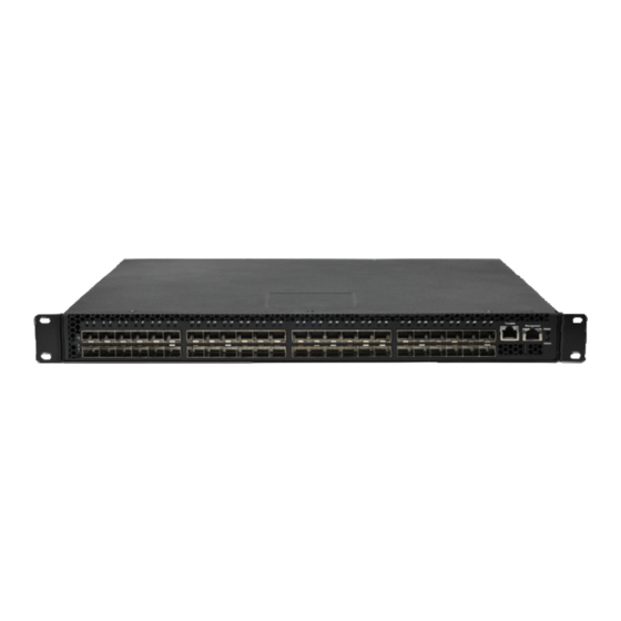
Page 10: Front-Panel Components
The upper LED indicators display power status. The lower LED indicators displays the status of the switch. An RS-232 DCE console port is for setting up and managing the Switch via a connection to a console terminal or PC using a terminal emulation program. Each port LED has two colors: Color green represents port link status;... -
Page 11: Management Options
CLI command. Web-based Management Interface After you have successfully installed the Switch, you can configure the Switch, monitor the LED panel, and display statistics graphically using a Web browser, such as Mozilla FireFox (version 3.6 or higher) or Microsoft®... - Page 12 • RFC 3289 - DIFFSERV-DSCP-TC • RFC 3289 - DIFFSERV-MIB • QOS-DIFFSERV-EXTENSIONS-MIB • QOS-DIFFSERV-PRIVATE-MIB • RFC 2674 802.1p • RFC 2932 (IPMROUTE-MIB) • Fortinet Enterprise MIB • ROUTING-MIB • MGMD-MIB • RFC 2934 PIM-MIB • DVMRP-STD-MIB • IANA-RTPROTO-MIB • MULTICAST-MIB •...
-
Page 13: Installation And Quick Startup
Installation and Quick Startup Package Contents Before you begin installing the Switch, confirm that your package contains the following items: • One FortiSwitch-548B Layer 2 10-Gigabit Managed Switch (Layer 3 features available if purchased) • Mounting kit: 2 mounting brackets and screws •... -
Page 14: Switch Installation
The Switch must have adequate space for ventilation and for accessing cable connectors. 2. Set the Switch on a flat surface and check for proper ventilation. Allow at least 5 cm (2 inches) on each side of the Switch and 15 cm (6 inches) at the back for the power cable. -
Page 15: Installing The Switch In A Rack
Installing the Switch in a Rack You can install the Switch in most standard 19-inch (48.3-cm) racks. Refer to the illustrations below. 1. Use the supplied screws to attach a mounting bracket to each side of the Switch. 2. Align the holes in the mounting bracket with the holes in the rack. -
Page 16: Quick Starting The Switch
Quick Starting the Switch 1. Read the device Installation Guide for the connectivity procedure. In-band connectivity allows access to the FortiSwitch-548B Series Switch locally. From a remote workstation,the device must be configured with IP information (IP address, subnet mask, and default gateway). -
Page 17: System Information Setup
Cap. Status - Indicates the port capabilities during auto-negotiation Details Displays all users that are allowed to access the switch User Access Mode - Shows whether the user is able to change parameters on the switch - 17 -... - Page 18 If you do not save config, all configurations will be lost when a power cycle is performed on the switch or when the switch is reset. Details Displays the Network Configurations IP Address - IP Address of the interface Default IP is 192.168.2.1...
- Page 19 3.5.5 Quick Start up Uploading from Switch to Out-of-Band PC Table 2-5. Quick Start up Uploading from Switch to Out-of-Band PC (XMODEM) Command copy startup-config xmodem <filename> 3.5.6 Quick Start up Downloading from Out-of-Band PC to Switch Table 2-6 Quick Start up Downloading from Out-of-Band PC to Switch...
- Page 20 Enter yes when the prompt pops up that asks if you want to reset the system. You can reset the switch or cold boot the switch; both work effectively. - 20 -...
-
Page 21: Console And Telnet Administration Interface
Switch. Hardware components in the Switch allow it to be an active part of a manageable network. These components include a CPU, memory for data storage, other related hardware, and SNMP agent firmware. Activities on the Switch can be monitored with these components, while the Switch can be manipulated to carry out specific tasks. - Page 22 • The console port is set for the following configuration: • Baud rate: 11,520 • Data width: 8 bits • Parity: none • Stop bits: 1 • Flow Control: none A typical console connection is illustrated below: Figure 3-1: Console Setting Environment - 22 -...
-
Page 23: Set Up Your Switch Using Telnet Access
Set Up your Switch Using Telnet Access Once you have set an IP address for your Switch, you can use a Telnet program (in a VT-100 compatible terminal mode) to access and control the Switch. Most of the screens are identical, whether accessed from the console port or from a Telnet interface. -
Page 24: Web-Based Management Interface
Web-Based Management Interface Overview The Fortinet FortiSwitch-548B Series Layer III plus QoS Managed Switch provides a built-in browser interface that lets you configure and manage it remotely using a standard Web browser such as Microsoft Internet Explorer 5.0 or later or Netscape Navigator 6.0 or later. This interface also allows for system monitoring and management of the switch. -
Page 25: How To Log In
How to log in The Fortinet FortiSwitch-548B Series Layer III plus QoS Managed Switch can be configured remotely from Microsoft Internet Explorer (version 5.0 or above), or Mozilla FireFox (version 3.6 or above). 1. Determine the IP address of your managed switch. -
Page 26: Web-Based Management Menu
Menus The Web-based interface enables navigation through several menus. The main navigation menu is on the left of every page and contains the screens that let you access all the commands and statistics the switch provides. Main Menus • System •... - Page 27 The Secondary Menus under the Main Menu contain a host of options that you can use to configure your switch. The online help contains a detailed description of the features on each screen. You can click the ‘help’ or the question mark at the top right of each screen to view the help menu topics.
- Page 28 • MAC-based VLAN — see “MAC-based Commands” • MAC-based Vocie VLAN — see “MAC-based Vocie VLAN Commands” • Voice VLAN — see “Voice VLAN Commands” • Filters — see “MAC Filters Commands” • GARP — see “GVRP and Bridge Extension Commands” •...
- Page 29 • Secure HTTP — see “HTTP Commands” • Secure Shell — see “Secure Shell (SSH) Commands” IPv6 • OSPFv3 — see “OSPFv3 Configuration Commands” • IPv6 Routes — see “IPv6 Routes Configuration Commands” • RIPv6 — see “RIPv6 Configuration Commands” •...
-
Page 30: Command Line Interface Structure And Mode-Based Cli
Command Line Interface Structure and Mode-based CLI The Command Line Interface (CLI) syntax, conventions, and terminology are described in this section. Each CLI command is illustrated using the structure outlined below. CLI Command Format Commands are followed by values, parameters, or both. Example 1 ip address <ipaddr>... -
Page 31: Cli Mode-Based Topology
CLI Mode-based Topology Parameters Parameters are order dependent. The text in bold italics should be replaced with a name or number. To use spaces as part of a name parameter, enclose it in double quotes like this: "System Name with Spaces". Parameters may be mandatory values, optional values, choices, or a combination. - Page 32 Conventions Network addresses are used to define a link to a remote host, workstation, or network. Network addresses are shown using the following syntax: Table 5-1. Network Address Syntax Address Type Format IPAddr A.B.C.D MacAddr YY:YY:YY:YY:YY:YY Double quotation marks such as "System Name with Spaces" set off user defined strings. If the operator wishes to use spaces as part of a name parameter then it must be enclosed in double quotation marks.
-
Page 33: Switching Commands
System Information and Statistics commands 7.1.1 show arp This command displays connectivity between the switch and other devices. The Address Resolution Protocol (ARP) cache identifies the MAC addresses of the IP stations communicating with the switch. Syntax show arp Default Setting... - Page 34 7.1.3 show process cpu This command provides the percentage utilization of the CPU by different tasks. Syntax show process cpu It is not necessarily the traffic to the CPU, but different tasks that keep the CPU busy Default Setting None Command Mode Privileged Exec Display Message...
- Page 35 This command is used to display/capture the current setting of different protocol packages supported on switch. This command displays/captures only commands with settings/configurations with values that differ from the default value. The output is displayed in script format, which can be used to configure another switch with the same configuration.
- Page 36 System Location: The text used to identify the location of the switch. May be up to 31 alpha-numeric characters. The factory default is blank. System Contact: The text used to identify a contact person for this switch. May be up to 31 alphanumeric characters. The factory default is blank.
- Page 37 Web Server Port: Displays the web server http port Web Server Java Mode: Specifies if the switch should allow access to the Java applet in the header frame. Enabled means the applet can be viewed. The factory default is disabled.
- Page 38 Part Number: Manufacturing part number. Hardware Version: The hardware version of this switch. It is divided into four parts. The first byte is the major version and the second byte represents the minor version. Loader Version: The release version maintenance number of the loader code currently running on the switch.
- Page 39 Fan Duty: Inner fan duty(%) of Power Supply now Below 10-Giga Interface information depend on plugging SFP+ Transceiver Interface = y... SFP+(The yth 10-Giga information of switch 1). 10 Gigabit Ethernet Compliance Codes: Transceiver’s compliance codes. Vendor Name: The SFP transceiver vendor name shall be the full name of the corporation, a commonly accepted abbreviation of the name of the corporation, the SCSI company code for the corporation, or the stock exchange code for the corporation.
- Page 40 User Name: The name the user will use to login using the serial port or Telnet. A new user may be added to the switch by entering a name in a blank entry. The user name may be up to 8 characters, and is not case sensitive.
-
Page 41: Device Configuration Commands
7.1.12 show command filter This command displays the information that begin/include/exclude the regular expression. Syntax show command [| begin/include/exclude <LINE>] Default Setting None Command Mode Privileged Exec Display Message command: Any show command of the CLI begin: Begin with the line that matches include: Include lines that match exclude: Exclude lines that match <LINE>: Regular Expression... - Page 42 Source: This port is a monitoring port. PC Mbr: This port is a member of a port-channel (LAG). Dest: This port is a probe port. Admin Mode: Selects the Port control administration state. The port must be enabled in order for it to be allowed into the network.
- Page 43 This command displays detailed statistics for a specific port or for all CPU traffic based upon the argument. Syntax show interface counters detailed {<slot/port> | switchport} <slot/port> - is the desired interface number. switchport - This parameter specifies whole switch or all interfaces. Default Setting None Command Mode Privileged Exec Display Message The display parameters when the argument is ' <slot/port>' are as follows:...
- Page 44 Total Packets Received (Octets): The total number of octets of data (including those in bad packets) received on the network (excluding framing bits but including FCS octets). This object can be used as a reasonable estimate of Ethernet utilization. If greater precision is desired, the etherStatsPkts and etherStatsOctets objects should be sampled before and after a common interval.
- Page 45 Packets RX and TX 2048-4095 Octets: The total number of packets (including bad packets) received that were between 2048 and 4095 octets in length inclusive (excluding framing bits but including FCS octets). Packets RX and TX 4096-9216 Octets: The total number of packets (including bad packets) received that were between 4096 and 9216 octets in length inclusive (excluding framing bits but including FCS octets).
- Page 46 Packets Transmitted 512-1023 Octets: The total number of packets (including bad packets) received that were between 512 and 1023 octets in length inclusive (excluding framing bits but including FCS octets). Packets Transmitted 1024-1518 Octets: The total number of packets (including bad packets) received that were between 1024 and 1518 octets in length inclusive (excluding framing bits but including FCS octets).
- Page 47 Most Address Entries Ever Used: The highest number of Forwarding Database Address Table entries that have been learned by this switch since the most recent reboot. Address Entries Currently in Use: The number of Learned and static entries in the Forwarding Database Address Table for this switch.
- Page 48 Maximum VLAN Entries: The maximum number of Virtual LANs (VLANs) allowed on this switch. Most VLAN Entries Ever Used: The largest number of VLANs that have been active on this switch since the last reboot. Static VLAN Entries: The number of presently active VLAN entries on this switch that have been created statically.
- Page 49 7.2.1.4 interface This command is used to enter Interface configuration mode. Syntax interface <slot/port> <slot/port> - is the desired interface number. Default Setting None Command Mode Global Config 7.2.1.5 speed-duplex This command is used to set the speed and duplex mode for the interface. The 10-Giga interfaces will not provide the following command.
- Page 50 all - This command represents all interfaces. no - This command will be back to 10G speed from 1G speed for all ports. Default Setting None Command Mode Global Config 7.2.1.6 negotiate This command enables automatic negotiation on a port. The default value is enabled. The 10-Giga interfaces will not provide the following command.
- Page 51 Command Mode Global Config 7.2.1.7 capabilities This command is used to set the capabilities on specific interface. The 10-Giga interfaces will not provide the following command. Syntax capabilities {{10 | 100 } {full-duplex | half-duplex}} | {1000 full-duplex } no capabilities {{10 | 100 } {full-duplex | half-duplex}} | {1000 full-duplex } 10 - 10BASE-T 100 - 100BASE-T 1000 - 1000BASE-T...
- Page 52 This command enables 802.3x flow control for the switch. 802.3x flow control only applies to full-duplex mode ports. Syntax storm-control flowcontrol no storm-control flowcontrol no - This command disables 802.3x flow control for the switch. Default Setting Disabled Command Mode Global Config This command enables 802.3x flow control for the specific interface.
- Page 53 7.2.1.9 storm-control flowcontrol pfc The PFC function is disabled by default. Only after enabling it, the PFC process also starts. Once the feature is enabled, the original basic IEEE 802.3x PAUSE control cannot be enabled. It means these two features cannot be enabled at the same time. 802.3x flow control only applies to full-duplex mode ports.
- Page 54 all - This command represents all ports. no - This command enables all ports. Default Setting Enabled Command Mode Global Config 7.2.1.11 description This command is used to create an alpha-numeric description of the port. Syntax description <description> no description no - This command removes the description of the port.
- Page 55 It is identified with interface 3/1 and is currently used when enabling VLANs for routing. Self: The value of the corresponding instance is the address of one of the switch’s physical interfaces (the system’s own MAC address).
- Page 56 Static Address (User-defined) count: The total user-defined addresses on the L2 MAC address Table. Total MAC Addresses in use: This number of addresses are used on the L2 MAC address table. Total MAC Addresses available: The switch supports max value on the L2 MAC address table. 7.2.2.3 show mac-addr-table interface This command displays the forwarding database entries.
- Page 57 It is identified with interface 3/1 and is currently used when enabling VLANs for routing. Self: The value of the corresponding instance is the address of one of the switch’s physical interfaces (the system’s own MAC address).
- Page 58 It is identified with interface 3/1 and is currently used when enabling VLANs for routing. Self: The value of the corresponding instance is the address of one of the switch’s physical interfaces (the system’s own MAC address).
- Page 59 Mac Address: A unicast MAC address for which the switch has forwarding and/or filtering information. The format is 6 or 8 two-digit hexadecimal numbers that are separated by colons, for example 01:23:45:67:89:AB. In an IVL system the MAC address will be displayed as 8 bytes. In an SVL system, the MAC address will be displayed as 6 bytes.
- Page 60 7.2.2.8 show mac-address-table stats This command displays the MFDB statistics. Syntax show mac-address-table stats Default Setting None Command Mode Privileged Exec Display Message Max MFDB Table Entries: This displays the total number of entries that can possibly be in the MFDB.
- Page 61 no - This command sets the forwarding database address aging timeout to 300 seconds. Default Setting Command Mode Global Config 7.2.3 VLAN Management 7.2.3.1 show vlan This command displays brief information on a list of all configured VLANs. Syntax show vlan Default Setting None Command Mode...
- Page 62 None Command Mode Privileged Exec Display Message VLAN ID: There is a VLAN Identifier (VID) associated with each VLAN. The range of the VLAN ID is 1 to 3965. VLAN Name: A string associated with this VLAN as a convenience. It can be up to 16 alphanumeric characters, including blanks.
- Page 63 Privileged Exec Display Message MAC Address: A unicast MAC address for which the switch has forwarding and/or filtering information. The format is 6 or 8 two-digit hexadecimal numbers that are separated by colons, for example 01:23:45:67:89:AB. In an IVL system the MAC address will be displayed as 8 bytes. In an SVL system, the MAC address will be displayed as 6 bytes.
- Page 64 <group-name> - The group name of an entry in the Protocol-based VLAN table. all – Displays the entire table. Default Setting None Command Mode Privileged Exec Display Message Group Name: This field displays the group name of an entry in the Protocol-based VLAN table. Group ID: This field displays the group identifier of the protocol group.
- Page 65 identified by the VLAN ID in the tag. In an untagged frame, the VLAN is the Port VLAN ID specified for the port that received this frame. When disabled, all frames are forwarded in accordance with the 802.1Q VLAN bridge specification. The factory default is disabled. GVRP: May be enabled or disabled.
- Page 66 vlan name <vlanid> <newname> no vlan name <vlanid> <vlanid> - VLAN ID (Range: 1 –3965). <newname> - Configure a new VLAN Name (up to 16 alphanumeric characters). no - This command sets the name of a VLAN to a blank string. The VLAN ID is a valid VLAN identification number.
- Page 67 Default Setting None Command Mode VLAN database 7.2.3.12 vlan makestatic This command changes a dynamically created VLAN (one that is created by GVRP registration) to a static VLAN (one that is permanently configured and defined). The ID is a valid VLAN identification number.
- Page 68 VLAN database 7.2.3.14 switchport acceptable-frame-type This command sets the frame acceptance mode per interface. For VLAN Only mode, untagged frames or priority frames received on this interface are discarded. For Admit All mode, untagged frames or priority frames received on this interface are accepted and assigned the value of the interface VLAN ID for this port.
- Page 69 Default Setting Admit all Command Mode Global Config 7.2.3.15 switchport ingress-filtering This command enables ingress filtering. If ingress filtering is disabled, frames received with VLAN IDs that do not match the VLAN membership of the receiving interface are admitted and forwarded to ports that are members of that VLAN.
- Page 70 Global Config 7.2.3.16 switchport native vlan This command changes the VLAN ID per interface. Syntax switchport native vlan <vlanid> no switchport native vlan <vlanid> <vlanid> - VLAN ID (Range: 1 –3965). no - This command sets the VLAN ID per interface to 1. Default Setting Command Mode Interface Config...
- Page 71 Syntax switchport allowed vlan {add [tagged | untagged] | remove} <vlan-list> <vlan-list> - VLAN ID (Range: 1 –3965) – separate non-consecutive IDs with ',' and no spaces and no zeros in between the range; Use '-' for range. add - The interface is always a member of this VLAN. This is equivalent to registration fixed. tagged - All frames transmitted for this VLAN will be tagged.
- Page 72 7.2.3.18 switchport tagging This command configures the tagging behavior for a specific interface in a VLAN to enable. If tagging is enabled, traffic is transmitted as tagged frames. If tagging is disabled, traffic is transmitted as untagged frames. The ID is a valid VLAN identification number. Syntax switchport tagging <vlan-list>...
- Page 73 7.2.3.19 switchport forbidden vlan This command used to configure forbidden VLANs. Syntax switchport forbidden vlan {add | remove} <vlan-list> no switchport forbidden <vlan-list> - VLAN ID (Range: 1 –3965) – separate non-consecutive IDs with ',' and no spaces and no zeros in between the range; Use '-' for range. add - VLAND ID to add.
- Page 74 switchport priority all <0-7> <0-7> - The range for the priority is 0-7. all – All interfaces Default Setting Command Mode Global Config 7.2.3.21 switchport protocol group This command adds the physical <slot/port> interface to the protocol-based VLAN identified by <group-name>.
- Page 75 no - This command removes the protocol-based VLAN group that is identified by this <group-name>. Default Setting None Command Mode Global Config This command adds all physical interfaces to the protocol-based VLAN identified by <group-name>. A group may have more than one interface associated with it. Each interface and protocol combination can only be associated with one group.
- Page 76 ipx - IPX protocol. no - This command removes the <protocol> from this protocol-based VLAN group that is identified by this <group-name>. The possible values for protocol are ip, arp, and ipx. Default Setting None Command Mode Global Config 7.2.4 Double VLAN commands 7.2.4.1 show dvlan-tunnel/ dot1q-tunnel...
- Page 77 7.2.4.2 switchport dvlan-tunnel/ dot1q-tunnel ethertype This command configures the ether-type for specific interface. The ether-type may have the values of 802.1Q, vMAN, or custom. If the ether-type has a value of custom, the optional value of the custom ether type must be set to a value from 0 to 65535. Syntax switchport {dvlan-tunnel | dot1q-tunnel } ethertype {802.1Q|custom <0-65535>|vman} Default Setting...
- Page 78 None Command Mode Privileged Exec User Exec Display Message GMRP Admin Mode: This displays the administrative mode of GARP Multicast Registration Protocol (GMRP) for the system. GVRP Admin Mode: This displays the administrative mode of GARP VLAN Registration Protocol (GVRP) for the system. 7.2.5.2 show gvrp configuration This command displays Generic Attributes Registration Protocol (GARP) information for one or all...
- Page 79 participant basis. The Leave All Period Timer is set to a random value in the range of LeaveAll- Time to 1.5*LeaveAllTime. Permissible values are 200 to 6000 centiseconds (2 to 60 seconds). The factory default is 1000 centiseconds (10 seconds). The finest granularity of specification is 1 centisecond (0.01 seconds).
- Page 80 Port GMRP Mode: Indicates the GMRP administrative mode for the port. It may be enabled or disabled. If this parameter is disabled, Join Time, Leave Time, and Leave All Time have no effect. The factory default is disabled. 7.2.5.4 show garp configuration This command displays GMRP and GVRP configuration information for one or all interfaces.
- Page 81 Disabled Command Mode Global Config 7.2.5.6 bridge-ext gmrp This command enables GARP Multicast Registration Protocol (GMRP) on the system. The default value is disabled. Syntax bridge-ext gmrp no bridge-ext gmrp no - This command disables GARP Multicast Registration Protocol (GMRP) on the system. Default Setting Disabled Command Mode...
- Page 82 This command enables GVRP (GARP VLAN Registration Protocol) for all ports. Syntax switchport gvrp all no switchport gvrp all all - All interfaces. no - This command disables GVRP (GARP VLAN Registration Protocol) for all ports. If GVRP is disabled, Join Time, Leave Time, and Leave All Time have no effect. Default Setting Disabled Command Mode...
- Page 83 functionality will be disabled on that interface. GMRP functionality will subsequently be re-enabled if routing is disabled and port-channel (LAG) membership is removed from an interface that has GMRP enabled. Syntax switchport gmrp all no switchport gmrp all all - All interfaces. no - This command disables GMRP Multicast Registration Protocol on a selected interface.
- Page 84 This command sets the GVRP join time for all ports and per GARP. Join time is the interval between the transmission of GARP Protocol Data Units (PDUs) registering (or re-registering) membership for a VLAN or multicast group. This command has an effect only when GVRP and GMRP are enabled. The time is from 10 to 100 (centiseconds).
- Page 85 This command sets the GVRP leave time per port. Leave time is the time to wait after receiving an unregister request for a VLAN or a multicast group before deleting the VLAN entry. This can be considered a buffer time for another station to assert registration for the same attribute in order to maintain uninterrupted service.
- Page 86 Global Config This command sets how frequently Leave All PDUs are generated per port. A Leave All PDU indicates that all registrations will be unregistered. Participants would need to rejoin in order to maintain registration. The value applies per port and per GARP participation. The time may range from 200 to 6000 (centiseconds).
- Page 87 Default Setting 1000 centiseconds (10 seconds) Command Mode Global Config 7.2.6 IGMP Snooping 7.2.6.1 ip igmp snooping The user can go to the CLI Global Configuration Mode to set IGMP Snooping on the system, use the ip igmp snooping global configuration command. Use the no ip igmp snooping to disable IGMP Snooping on the system.
- Page 88 7.2.6.3 ip igmp snooping fast-leave The user can go to the CLI Global/Interface Configuration Mode to set IGMP Snooping fast-leave admin mode on a selected interface or all interfaces, use the ip igmpsnooping fast-leave global/interface configuration command. Use the no ip igmp snooping fast-leave disable IGMP Snooping fast-leave admin mode.
- Page 89 7.2.6.5 ip igmp snooping max-response-time The user can go to the CLI Interface Global/Interface Configuration Mode to set the IGMP Maximum Response time for the system, on a particular interface, use the ip igmp snooping max-response-time <1-25> global/interface configuration command. Use the no ip igmp snooping max-response-time return to default value 10 Syntax ip igmp snooping max-response-time <1-25>...
- Page 90 7.2.6.7 ip igmp snooping mrouter interface The user can go to the CLI Interface Configuration Mode to configure the interface as a multicast router-attached interface or configure the VLAN ID for the VLAN that has the multicast router attached mode enabled, use the ip igmp snooping mrouter interface|<vlanId> interface configuration command.
- Page 91 Syntax set igmp fast-leave <vlanid> no set igmp fast-leave <vlanid> <vlanid> - VLAN ID (Range: 1 – 3965). Default Setting Disabled Command Mode VLAN Mode 7.2.6.10 set igmp groupmembership-interval The user can go to the CLI VLAN Configuration Mode to set the IGMP Group Membership Interval time on a particular VLAN, use the set igmpgroupmembership-interval <vlanid>...
- Page 92 no set igmp maxresponse <vlanid> < vlanid > - VLAN ID (Range: 1 – 3965). <1-25> -- This value must be less than the IGMP Query Interval time value. The range is 1 to 25 seconds. Default Setting Command Mode VLAN Mode 7.2.6.12 set igmp mcrtrexpiretime The user can go to the CLI Interface VLAN Configuration Mode to set the Multicast Router Present...
- Page 93 Fast Leave Mode: Indicates whether IGMP Snooping Fast Leave is active on the interface. Group Membership Interval: Shows the amount of time in seconds that a switch will wait for a report from a particular group on a particular interface, which is participating on the interface, before deleting the interface from the entry.
- Page 94 Fast Leave Mode: Indicates whether IGMP Snooping Fast Leave is active on the VLAN. Group Membership Interval: Shows the amount of time in seconds that a switch will wait for a report from a particular group on a particular interface, which is participating in the VLAN, before deleting the interface from the entry.
- Page 95 show ip igmp snooping mrouter vlan <slot/port> <slot/port> - Interface number. Default Setting None Command Mode Privilege Exec Display Message VLAN ID: Displays the list of VLANs of which the interface is a member. Slot/Port: Shows the interface on which multicast router information is being displayed. 7.2.6.17 show ip igmp snooping static The user can go to the Privilege Exec to display IGMP snooping static information, use the show ip igmp snooping static Privilege command.
- Page 96 Command Mode Privilege Exec Display Message MAC Address: A multicast MAC address for which the switch has forwarding or filtering information. The format is twodigit hexadecimal numbers that are separated by colons, for example 01:00:5e:67:89:AB. Type: The type of entry, which is either static (added by the user) or dynamic (added to the table as a result of a learning process or protocol.)
- Page 97 ip igmp snooping querier address <ip-address> no ip igmp snooping querier address <ip-address> - ip address Default Setting 0.0.0.0 Command Mode Global Config 7.2.7.3 ip igmp snooping querier query-interval The user can go to the CLI Global Configuration Mode to set IGMP snooping querier query interval, use the ip igmp snooping querier query-interval <1-1800>...
- Page 98 Default Setting 60 seconds Command Mode Global Config 7.2.7.5 ip igmp snooping querier version The user can go to the CLI Global Configuration Mode to set IGMP snooping querier version, use the ip igmp snooping querier version <1-2> global configuration command. Use the no ip igmp snooping querier version return to default value zero.
- Page 99 7.2.7.7 ip igmp snooping querier vlan address The user can go to the CLI Global Configuration Mode to set IGMP snooping querier vlan address, use the ip igmp snooping querier vlan <1-3965> address <ip-address> global configuration command. Use the no ip igmp snooping querier vlan <1-3965> address return to default value zero. Syntax ip igmp snooping querier vlan <1-3965>...
- Page 100 Display Information IGMP Snooping Querier Vlan Mode: Display the administrative mode for IGMP Snooping for the switch. Querier Election Participation Mode: Displays the querier election participate mode on the VLAN. When this mode is disabled, up on seeing a query of the same version in the vlan, the snooping querier move to non querier state.
- Page 101 Operational Version: Displays the operational IGMP protocol version of the querier. 7.2.7.11 show ip igmp snooping querier detail This command display all of IGMP snooping querier information on the system. Syntax show ip igmp snooping querier detail Command Mode Privilege Exec Display Information IGMP Snooping Querier Mode: Administrative mode for IGMP Snooping.
- Page 102 Fast Leave Mode: Indicates whether MLD Snooping Fast Leave is active on the interface. Group Membership Interval: Shows the amount of time in seconds that a switch will wait for a report from a particular group on a particular interface, which is participating on the interface, before deleting the interface from the entry.
- Page 103 show ipv6 mld snooping mrouter interface <slot/port> Default Setting None Command Mode Privileged Exec User Exec Display Message Interface: Shows the interface on which multicast router information is being displayed. Multicast Router Attached: Indicates whether multicast router is statically enabled on the interface. VLAN ID: Displays the list of VLANs of which the interface is a member.
- Page 104 Command Mode Privileged Exec Display Message MAC Address: A multicast MAC address for which the switch has forwarding or filtering information. The format is twodigit hexadecimal numbers that are separated by colons, for example 33:33:45:67:89:AB. Type: The type of entry, which is either static (added by the user) or dynamic (added to the table as a result of a learning process or protocol.)
- Page 105 7.2.8.6 ipv6 mld snooping The user can go to the CLI Global Configuration Mode to set MLD Snooping on the system , use the ipv6 mld snooping global configuration command. Use the no ipv6 mld snooping to disable MLD Snooping on the system. Syntax Ipv6 mld snooping no ipv6 mld snooping...
- Page 106 Disabled Command Mode Global Config Interface Config 7.2.8.9 ipv6 mld snooping fast-leave The user can go to the CLI Global/Interface Configuration Mode to set MLD Snooping fast-leave admin mode on a selected interface or all interfaces, use the ipv6 mld snooping fast-leave global/interface configuration command.
- Page 107 7.2.8.11 ipv6 mld snooping max-response-time The user can go to the CLI Interface Global/Interface Configuration Mode to set the MLD Maximum Response time for the system, on a particular interface, use the ipv6 mld snooping max-response-time <1-65> global/interface configuration command. Use the no ipv6 mld snooping max-response-time return to default value 10.
- Page 108 Syntax Ipv6 mld snooping mrouter interface interface|<vlanId> no ipv6 mld snooping mrouter interface|<vlanId> Default Setting None Command Mode Interface Config 7.2.8.14 ipv6 mld snooping static The user can go to the Global Mode and add a port to ipv6 multicast group, use the ipv6 mld snooping static Global command.
- Page 109 7.2.8.16 set mld fast-leave The user can go to the CLI VLAN Configuration Mode to set MLD Snooping fast-leave admin mode on a particular VLAN, use the set mld fast-leave <vlanid> vlan configuration command. Use the no set mld fast-leave <vlanid> disable MLD Snooping fast-leave admin mode. Syntax set mld fast-leave <vlanid>...
- Page 110 Default Setting Command Mode VLAN Mode 7.2.8.19 set ipv6 mld mcrtrexpiretime The user can go to the CLI Interface VLAN Configuration Mode to set the Multicast Router Present Expiration time on a particular VLAN, use the set mld mcrtrexpiretime <vlanid> <0-3600> vlan configuration command.
- Page 111 Querier Address: Specify the Snooping Querier Address to be used as source address in periodic MLD queries. This address is used when no address is configured on the VLAN on which query is being sent. MLD Version: Specify the MLD protocol version used in periodic MLD queries. Querier Query Interval: Specify the time interval in seconds between periodic queries sent by the snooping querier.
- Page 112 Syntax show ipv6 mld snooping querier detail Default Setting None Command Mode Privileged Exec User Exec Display Message MLD Snooping Querier Mode: Administrative mode for MLD Snooping. The default is disable Querier Address: Specify the Snooping Querier Address to be used as source address in periodic MLD queries.
- Page 113 7.2.9.5 ipv6 mld snooping querier address The user can go to the CLI Global Configuration Mode to set MLD snooping querier address, use the ipv6 mld snooping querier address <ipv6-address> global configuration command. Use the ipv6 mld snooping querier address <ipv6-address> return to default value zero. Syntax ipv6 mld snooping querier address <ipv6-address>...
- Page 114 Command Mode Global Config 7.2.9.8 ipv6 mld snooping querier vlan The user can go to the CLI Global Configuration Mode to set MLD snooping querier vlan admin mode, use the ipv6 mld snooping querier vlan <1-3965> global configuration command. Use the no ipv6 mld snooping querier vlan <1-3965>...
- Page 115 Mbr Ports: This field lists the ports that are members of this port-channel, in slot/port notation. Active Ports: This field lists the ports that are actively participating in this port-channel. This command displays an overview of a specificed port-channel (LAG) on the switch. - 115 -...
- Page 116 Port Speed: Speed of the port-channel port. Port Active: This field lists the ports that are actively participating in the port-channel (LAG). This command displays an overview of all port-channels (LAGs) on the switch. Syntax show port-channel all...
- Page 117 Log. Intf: The logical slot and the logical port. Channel Name: The name of this port-channel (LAG). You may enter any string of up to 15 alphanumeric characters. Link: Indicates whether the Link is up or down. Admin Mode: May be enabled or disabled. The factory default is enabled. Type: This field displays the status designating whether a particular port-channel (LAG) is statically or dynamically maintained.
- Page 118 7.2.10.3 port-channel adminmode all This command sets every configured port-channel with the same administrative mode setting. Syntax port-channel adminmode all no port-channel adminmode all no - This command disables a port-channel (LAG). The option all sets every configured port-channel with the same administrative mode setting. Default Setting Enabled Command Mode...
- Page 119 port-channel linktrap {<logical slot/port> | all} no port-channel linktrap {<logical slot/port> | all} <logical slot/port> - The port-channel interface number. all - all port-channel interfaces. no - This command disables link trap notifications for the port-channel (LAG). The interface is a logical slot and port for a configured port-channel.
- Page 120 This command for CLI will configured the mode of load balance on the specific Port Channel. The parameter “ src-mac | dst-mac | dst-src-mac | src-ip | dst-ip| dst-src-ip ” represent the mode used to be set for port-channel load balance. Syntax load-balance { src-mac| dst-mac | dst-src-mac | src-ip | dst-ip| dst-src-ip } no load-balance...
- Page 121 7.2.10.8 port-channel system priority This command defines a system priority for the port-channel (LAG). Syntax port-channel system priority <priority-value> <priority-value> - valid value 0-65535. Default Setting 32768 Command Mode Global Config 7.2.10.9 adminmode This command enables a port-channel (LAG) members. The interface is a logical slot and port for a configured port-channel.
- Page 122 no - This command disables Link Aggregation Control Protocol (LACP) on a port. Default Setting Enabled Command Mode Interface Config This command enables Link Aggregation Control Protocol (LACP) on all ports. Syntax lacp all no lacp all all - All interfaces. no - This command disables Link Aggregation Control Protocol (LACP) on all ports.
- Page 123 Interface Config This command set <actor | partner> admin state value of Link Aggregation Control Protocol (LACP) on a port. Syntax lacp <actor|partner> admin state <individual|longtimeout|passive> no lacp <actor|partner> admin state <individual|longtimeout|passive> individual - Set lacp admin state to individual. Use no form to set to aggregation. longtimeout - Set lacp admin state longtimeout.
- Page 124 This command set <actor | partner> system priority value of Link Aggregation Control Protocol (LACP). Syntax lacp <actor|partner> system priority <priority-value> no lacp <actor|partner> system priority <priority-value> – range 0-65535. no - This command restores <actor | partner> system priority value of Link Aggregation Control Protocol (LACP).
- Page 125 Syntax channel-group <logical slot/port> <logical slot/port> - Port-Channel Interface number. Default Setting None Command Mode Interface Config Command Usage The maximum number of members for each Port-Channel is 8. 7.2.10.13 delete-channel-group This command deletes the port from the port-channel (LAG). The interface is a logical slot and port number of a configured port-channel.
- Page 126 Default Setting None Command Mode Global Config 7.2.11 Storm Control 7.2.11.1 show storm-control This command is used to display broadcast storm control information. Syntax show storm-control broadcast Default Setting None Command Mode Privileged Exec Display Message Intf: Displays interface number. Mode: Displays status of storm control broadcast.
- Page 127 (as represented in “Broadcast Storm Recovery Thresholds” table) of the link speed, the switch discards the broadcasts traffic until the broadcast traffic returns to the threshold percentage or less. The full implementation is depicted in the “Broadcast Storm Recovery Thresholds”...
- Page 128 Default Setting Disabled Command Mode Interface Config This command enables broadcast storm recovery mode on all interfaces. Syntax storm-control broadcast no storm-control broadcast no - This command disables broadcast storm recovery mode on all interfaces. Default Setting Disabled Command Mode GlobaI Config 7.2.11.3 storm-control multicast This command enables multicast storm recovery mode on the selected interface.
- Page 129 storm-control multicast no storm-control multicast no - This command disables multicast storm recovery mode on all interfaces. Default Setting None Command Mode Global Config 7.2.11.4 storm-control unicast This command enables unicast storm recovery mode on the selected interface. Syntax storm-control unicast no storm-control unicast no - This command disables unicast storm recovery mode on the selected interface.
- Page 130 Global Config 7.2.11.5 switchport broadcast packet-rate This command will protect your network from broadcast storms by setting a threshold level for broadcast traffic on each port. Syntax switchport broadcast packet-rate {1 | 2 | 3 | 4} 1 - Threshold level represents 64 pps for 1G Port or 1042 pps for 10G port. 2 - Threshold level represents 128 pps for 1G Port or 2084 pps for 10G port.
- Page 131 Command Mode Global Config 7.2.11.6 switchport multicast packet-rate This command will protect your network from multicast storms by setting a threshold level for multicast traffic on each port. Syntax switchport multicast packet-rate {1 | 2 | 3 | 4} 1 - Threshold level represents 64 pps for 1G Port or 1042 pps for 10G port. 2 - Threshold level represents 128 pps for 1G Port or 2084 pps for 10G port.
- Page 132 Level 4 Command Mode Global Config 7.2.11.7 switchport unicast packet-rate This command will protect your network from unicast storms by setting a threshold level for unicast traffic on each port. Syntax switchport unicast packet-rate {1 | 2 | 3 | 4} 1 - Threshold level represents 64 pps for 1G Port or 1042 pps for 10G port.
- Page 133 Default Setting Level 4 Command Mode Global Config 7.2.12 L2 Priority 7.2.12.1 show queue cos-map This command displays the class of service priority map on specific interface. Syntax show queue cos-map [<slot/port>] <slot/port> - Interface number. Default Setting None Command Mode Privileged Exec Display Message User Priority: Displays the 802.1p priority to be mapped.
- Page 134 priority queue Command Mode Interface Config 7.2.13 Port Mirror 7.2.13.1 show port-monitor session This command displays the Port monitoring information for the specified session. Syntax show port-monitor session <Session Number> <Session Number> - session number. Default Setting None Command Mode Privileged Exec Display Message Session ID: indicates the session ID.
- Page 135 7.2.13.2 port-monitor session This command configures a probe port and a monitored port for monitor session (port monitoring). Use the source interface <slot/port> parameter to specify the interface to monitor. Use rx to monitor only ingress packets, or use tx to monitor only egress packets. If you do not specify an {rx | tx} option, the destination port monitors both ingress and egress packets.
- Page 136 port-monitor session <session-id> mode no port-monitor session <session-id> mode <session-id> - Session ID. no - This command disables port-monitoring function for a monitor session. Default Setting None Command Mode Global Config 7.2.14 Link State 7.2.14.1 show link state Show link state information. Syntax show link state Command Mode...
- Page 137 7.2.15.1 show port backup Show port-backup information. Syntax show port-backup Command Mode Privileged EXEC Display Message Admin Mode: Indicates whether or not port-backup is active on the switch. Group ID: The Group ID for each displayed row. - 137 -...
- Page 138 Mode: Indicates whether or not the group is active. MAC Update: Indicates whether or not mac-move-update is enable on the group. Active Port: Display the active port number. Backup Port: Display the active port number. Current Active Port: Display the current active port number. 7.2.15.2 port-backup Enable/Disable the port backup admin mode.
- Page 139 7.2.16 FIP Snooping 7.2.16.1 show fip-snooping This command displays fip-snooping whether enable or disable. Syntax show fip-snooping Default Setting None Command Mode Privileged Exec Display Message FIP Snooping: fip-snooping function status. 7.2.16.2 show fip-snooping enode This command displays the ENode connections for the entire system. Syntax show fip-snooping enode Default Setting...
- Page 140 VLAN ID: ID number of the VLAN to which the FCF belongs. FC MAP: May FC-Map value used by the FCF. FCF MAC: MAC address of the FCF. Switch Name: Name ID. Fabric Name: Name of the FCF. - 140 -...
- Page 141 7.2.16.5 show fip-snooping vlan This command displays FIP snooping whether enable or disable on specific VLAN. Syntax show fip-snooping vlan {< 1-3965> | all} <1 - 3965> - VLAN ID. all - This command represents all interfaces. Default Setting None Command Mode Privileged Exec Display Message...
- Page 142 7.2.16.7 fip-snooping vlan This command enables FIP snooping on a VLAN. VLAN must be configured before it can be used. Once VLAN is enabled, the FIP packets will be snooped only on the configured VLANs. FIP snooping is disabled on VLANs by default. Syntax fip-snooping vlan <vlan id>...
- Page 143 7.2.17.2 show queue ets scheduler-type This command displays ETS function on specific interface for the entire system. Syntax show queue ets scheduler-type <slot/port> <slot/port> - Interface number. Default Setting None Command Mode Privileged Exec Display Message Interface: Name of the interface to which the ETS is enabled. Scheduler-type: ETS scheduler type.
- Page 144 show queue ets pg-mapping <slot/port> Default Setting None Command Mode Privileged Exec Display Message Interface: Name of the interface to which the ETS is enabled. pg-mapping: ETS priority to priority group mapping list. 7.2.17.5 queue ets The ETS function is disabled by default. Only after enabling it, the ETS process also starts. Syntax queue ets no queue ets...
- Page 145 WERR - Set ETS scheduler type to WERR no - This command restores the scheduler type to WERR. Default Setting werr Command Mode Interface Config 7.2.17.7 queue ets weight This command configures the weight ratio of the two priority groups (LAN and SAN) for an interface. The sum of these two weight values should meet 100 in percentage.
- Page 146 <0 - 7> - Priority Id from 0 to 7. lan - Sets ETS Priority Id to LAN priority group san - Sets ETS Priority Id to SAN priority group ipc - Sets ETS Priority Id to IPC priority group no - This command restores the priority to priority group mapping list to default value.
- Page 147 outer CFI: Displays Outer Packet CFI for Congestion Notification Message inner CFI: Displays Inner Packet CFI for Congestion Notification Message inner Dot1p: Displays Inner Packet Priority for Congestion Notification Message no-generate: Generate CNM or not. 7.2.18.2 show congestion-notify interface This command displays CN function global parameter on system. Syntax show congestion-notify interface {<slot/port>...
- Page 148 Disabled Command Mode Interface Config 7.2.18.4 congestion-notify tag The user can go to the CLI Global Configuration Mode to configure the CNTAG Ether Type is recognized by parsing stages. Use the ‘congestion-notify tag ethertype recognize’ global configuration command. Use the ‘no congestion-notify tag ethertype recognize’ to configure CNTAG Ether Type is unrecognized. Syntax congestion-notify tag ethertype recognize no congestion-notify tag ethertype recognize...
- Page 149 7.2.18.5 congestion-notify enable The user can go to the CLI Global Configuration Mode to enable handling congestion notification message. Use the ‘congestion-notify enable’ global configuration command. Use the ‘no congestion-notify enable’ to disable handling congestion notification message. Syntax congestion-notify enable no congestion-notify enable no - This command disables handling congestion notification message.
- Page 150 Syntax congestion-notify CPID devid < 0-16777215 > no congestion-notify CPID devid <0-16777215> - This command sets the Device ID of CPID no - This command configure device identifier to default value. Default Setting Command Mode Global Config The user can go to the CLI Global Configuration Mode to configure the LSB field of CPID of CNM payload.
- Page 151 no congestion-notify outer { CFI | Dot1p | TPID| vlan} <-1-1> - This command sets value of CNM's outer VLAN tag's CFI bits. <-1-7> - This command sets value of CNM's outer VLAN tag's 802.1p bits. <0-65535> - This command sets value of CNM's outer VLAN tag's TPID. <0-4095>...
-
Page 152: Management Commands
This command displays configuration settings associated with the switch's network interface. The network interface is the logical interface used for in-band connectivity with the switch via any of the switch's front panel ports. The configuration parameters associated with the switch's network interface do not affect the configuration of the front panel ports through which traffic is switched or routed. - Page 153 Web Port: This field is used to set the HTTP Port Number. The value must be in the range of 1 to 65535. Port 80 is the default value. Java Mode: Specifies if the switch should allow access to the Java applet in the header frame. Enabled means the applet can be viewed. The factory default is disabled.
- Page 154 <1518-9216> - Max frame size (Range: 1518 - 9216). no - This command sets the default maximum transmission unit (MTU) size (in bytes) for the interface. Default Setting 1518 Command Mode Interface Config 7.3.1.4 interface vlan This command is used to enter Interface-vlan configuration mode. Syntax interface vlan <vlanid>...
- Page 155 Subnet Mask: 0.0.0.0 Command Mode Interface-Vlan Config Command Usage Once the IP address is set, the VLAN ID’s value will be assigned to management VLAN. 7.3.1.6 ip default-gateway This command sets the IP Address of the default gateway. Syntax ip default-gateway <gateway> no ip default-gateway <...
- Page 156 <ipaddr> - Configure a IP address to the filter. no - Remove this IP address from filter. Default Setting None Command Mode Global Config 7.3.2 Serial Interface Commands 7.3.2.1 show line console This command displays serial communication settings for the switch. - 156 -...
- Page 157 Serial Port Login Timeout (minutes): Specifies the time, in minutes, of inactivity on a Serial port connection, after which the Switch will close the connection. Any numeric value between 0 and 160 is allowed, the factory default is 5. A value of 0 disables the timeout.
- Page 158 7.3.2.3 baudrate This command specifies the communication rate of the terminal interface. The supported rates are 1200, 2400, 4800, 9600, 19200, 38400, 57600, 115200. Syntax baudrate {1200 | 2400 | 4800 | 9600 | 19200 | 38400 | 57600 | 115200} no baudrate no - This command sets the communication rate of the terminal interface to 115200.
- Page 159 Syntax password-threshold <0-120> no password-threshold <threshold> - max threshold (Range: 0 - 120). no - This command sets the maximum value to the default. Default Setting Command Mode Line Config 7.3.2.6 silent-time This command uses to set the amount of time the management console is inaccessible after the number of unsuccessful logon tries exceeds the threshold value.
- Page 160 Default Setting Command Mode Line Config 7.3.3 Telnet Session Commands 7.3.3.1 telnet This command establishes a new outbound telnet connection to a remote host. Syntax telnet <host> [port] [debug] [line] [echo] <host> - A hostname or a valid IP address. [port] - A valid decimal integer in the range of 0 to 65535, where the default value is 23.
- Page 161 Command Mode Privileged Exec Display Message Remote Connection Login Timeout (minutes): This object indicates the number of minutes a remote connection session is allowed to remain inactive before being logged off. A zero means there will be no timeout. May be specified as a number from 0 to 160. The factory default is 5. Maximum Number of Remote Connection Sessions: This object indicates the number of simultaneous remote connection sessions allowed.
- Page 162 Syntax exec-timeout <1-160> no exec-timeout <sec> - max connect time (Range: 1 -160). no - This command sets the remote connection session timeout value, in minutes, to the default. Default Setting Command Mode Line Vty 7.3.3.5 password-threshold This command is used to set the password instruction threshold limited for the number of failed login attempts.
- Page 163 no - This command sets the value to the default. Default Setting Command Mode Line Vty 7.3.3.7 maxsessions This command specifies the maximum number of remote connection sessions that can be established. A value of 0 indicates that no remote connection can be established. The range is 0 to 5. Syntax maxsessions <0-5>...
- Page 164 7.3.3.9 sessions This command regulates new telnet sessions. If sessions are enabled, new telnet sessions can be established until there are no more sessions available. If sessions are disabled, no new telnet sessions are established. An established session remains active until the session is ended or an abnormal network error ends it.
- Page 165 7.3.3.11 telnet maxsessions This command specifies the maximum number of simultaneous outbound telnet sessions. A value of 0 indicates that no outbound telnet session can be established. Syntax telnet maxsessions <0-5> no maxsessions <0-5> - max sessions (Range: 0 - 5). no - This command sets the maximum value to be 5.
- Page 166 Syntax show telnet Default Setting None Command Mode Privileged Exec User Exec Display Message Outbound Telnet Login Timeout (in minutes) Indicates the number of minutes an outbound telnet session is allowed to remain inactive before being logged off. A value of 0, which is the default, results in no timeout.
- Page 167 7.3.4.2 sshc sessions This command regulates new outbound ssh connections. If enabled, new outbound ssh sessions can be established until it reaches the maximum number of simultaneous outbound ssh sessions allowed. If disabled, no new outbound ssh session can be established. An established session remains active until the session is ended or an abnormal network error ends it.
- Page 168 Changing the timeout value for active sessions does not become effective until the session is reaccessed. Any keystroke will also activate the new timeout duration. Syntax sshc exec-timeout <1-160> no sshc exec-timeout <1-160> - max connect time (Range: 1 -160). no - This command sets the remote connection session timeout value, in minutes, to the default.
- Page 169 The SNMP agent of the switch complies with SNMP versions 1, 2c, and 3 (for more about the SNMP specification, see the SNMP RFCs). The SNMP agent sends traps through TCP/IP to an external SNMP manager based on the SNMP configuration (the trap receiver and other SNMP community parameters).
- Page 170 Multiple Users Flag: May be enabled or disabled. The factory default is enabled. Indicates whether a trap will be sent when the same user ID is logged into the switch more than once at the same time (either via telnet or serial port).
- Page 171 Global Config 7.3.5.4 snmp-server location This command sets the physical location of the switch. The range for name is from 1 to 31 alphanumeric characters. Syntax snmp-server location <loc> <loc> - range is from 1 to 31 alphanumeric characters. Default Setting...
- Page 172 This command activates an SNMP community. If a community is enabled, an SNMP manager associated with this community manages the switch according to its access right. If the community is disabled, no SNMP requests using this community are accepted. In this case the SNMP manager associated with this community cannot manage the switch until the Status is changed back to Enable.
- Page 173 The community name may be up to 16 alphanumeric characters. Default Setting 0.0.0.0 Command Mode Global Config This command restricts access to switch information. The access mode is read-only (also called public) or read/write (also called private). Syntax snmp-server community {ro | rw} <name> <name> - community name.
- Page 174 range of IP addresses from which SNMP clients may use that community to access the device. A value of 0.0.0.0 allows access from any IP address. Otherwise, this value is ANDed with the mask to determine the range of allowed client IP addresses. The name is the applicable community name. Syntax snmp-server community ipaddr <ipaddr>...
- Page 175 Enabled Command Mode Global Config This command enables Link Up/Down traps for the entire switch. When enabled, link traps are sent only if the Link Trap flag setting associated with the port is enabled (see ‘snmp trap link-status’ command). Syntax...
- Page 176 This command enables Multiple User traps. When the traps are enabled, a Multiple User Trap is sent when a user logs in to the terminal interface (EIA 232 or telnet) and there is an existing terminal interface session. Syntax snmp-server enable traps multiusers no snmp-server enable traps multiusers no - This command disables Multiple User trap.
- Page 177 virtauthentication-failure | virt-bad-packet | virt-config-error} | if-rx {all | if-rx-packet} | lsa {all | lsa-maxage | lsa-originate} | overflow {all | lsdb-overflow | lsdb-approaching-overflow} | retransmit {all | packets | virt-packets} | rtb {all, rtb-entry-info} | state-change {all | if-state-change | neighbor-state-change | virtif-statechange | virtneighbor-state-change}} no snmp-server enable traps ospfv3 {all | errors {all | authentication-failure | bad-packet | config-error | virtauthentication-failure | virt-bad-packet | virt-config-error} | if-rx {all | if-rx-packet} | lsa {all |...
- Page 178 This command displays SNMP trap receivers. Trap messages are sent across a network to an SNMP Network Manager. These messages alert the manager to events occurring within the switch or on the network. Six trap receivers are simultaneously supported.
- Page 179 Syntax snmptrap snmpversion <name> <ipaddr> <snmpversion> Default Setting Snmpv2 Command Mode Global Config 7.3.6.3 snmp trap link-status This command enables link status traps by interface. This command is valid only when the Link Up/Down Flag is enabled. See ‘snmpserver enable traps linkmode’ command. Syntax snmp trap link-status no snmp trap link-status...
- Page 180 Default Setting Disabled Command Mode Global Config 7.3.6.4 snmptrap <name> ipaddr <ipaddr> <snmpversion> This command adds an SNMP trap name. The maximum length of the name is 16 case-sensitive alphanumeric characters. Syntax snmptrap <name> ipaddr <ipaddr> <snmpversion> no snmptrap <name> <ipaddr> <snmpversion> <name>...
- Page 181 - This command deactivates an SNMP trap. Trap receivers are inactive (not able to receive traps). Default Setting None Command Mode Global Config 7.3.7 HTTP commands 7.3.7.1 show ip http This command displays the http settings for the switch. Syntax show ip http Default Setting - 181 -...
- Page 182 7.3.7.2 ip javamode This command specifies whether the switch should allow access to the Java applet in the header frame of the Web interface. When access is enabled, the Java applet can be viewed from the Web interface. When access is disabled, the user cannot view the Java applet.
- Page 183 This command enables access to the switch through the Web interface. When access is enabled, the user can login to the switch from the Web interface. When access is disabled, the user cannot login to the switch's Web server.
- Page 184 ip http secure-port <portid> no ip http secure-port <portid> - SSLT Port value. no - This command is used to reset the SSLT port to the default value. Default Setting Command Mode Global Config 7.3.7.6 ip http secure-server This command is used to enable the secure socket layer for secure HTTP. Syntax ip http secure-server no ip http secure-server...
- Page 185 Max SSH Sessions Allowed: The maximum number of inbound SSH sessions allowed on the switch. SSH Timeout: This field is the inactive timeout value for incoming SSH sessions to the switch. Keys Present: Indicates whether the SSH RSA and DSA key files are present on the device.
- Page 186 no - This command is used to disable SSH. Default Setting Disabled Command Mode Global Config 7.3.8.3 ip ssh protocol This command is used to set or remove protocol levels (or versions) for SSH. Either SSH1 (1), SSH2 (2), or both SSH 1 and SSH 2 (1 and 2) can be set. Syntax ip ssh protocol <protocollevel1>...
- Page 187 7.3.8.5 ip ssh timeout This command sets the SSH connection session timeout value, in minutes. A session is active as long as the session has been idle for the value set. A value of 0 indicates that a session remains active indefinitely.
- Page 188 Default Setting None Command Mode Global Config 7.3.10.2 ip dhcp client-identifier This command is used to specify the DCHP client identifier for this switch. Use the no form to restore to default value. Syntax - 188 -...
- Page 189 ip dhcp client-identifier {text <text> | hex <hex>} no ip dhcp client-identifier <text> - A text string. (Range: 1-32 characters). <hex> - The hexadecimal value (00:00:00:00:00:00). no - This command is used to restore to default value. Default Setting System Burned In MAC Address Command Mode Global Config 7.3.11...
- Page 190 Default Setting None Command Mode Global Config 7.3.11.3 serviceport protocol This command specifies the oob configuration protocol to be used. If you modify this value, the change is effective immediately. Syntax serviceport protocol {bootp | dhcp | dhcp6 | none [dhcp6]} <bootp>...
- Page 191 Packets Discarded - The total number of BOOTP/DHCP packets discarded by this Relay Agent since the last time the switch was reset. 7.3.12.2 bootpdhcprelay maxhopcount This command is used to set the maximum relay agent hops for BootP/DHCP Relay on the system.
- Page 192 IP Address: The IP address associated with this agent. 7.3.13.2 show sflow pollers The user can go to the CLI Privilege Exec to get the sFlow polling instances created on the switch, use the show sflow pollers Privilege command. Syntax...
- Page 193 Port: The destination Layer4 UDP port for sFlow datagrams. IP Address: The sFlow receiver IP address. 7.3.13.4 show sflow samplers The user can go to the CLI Privilege Exec to get the sFlow sampling instances created on the switch, use the show sflow samplers Privilege command. Syntax...
- Page 194 Command Mode Privilege Exec Display Message Sampler Data Source: The sFlowDataSource (slot/port) for this sFlow sampler. This agent will support Physical ports only. Receiver Index: The sFlowReceiver configured for this sFlow sampler. Packet Sampling Rate: The statistical sampling rate for packet sampling from this source. Max Header Size: The maximum number of bytes that should be copied from a sampled packet to form a flow sample.
- Page 195 7.3.13.7 set sflow maximum datagram size The user can go to the CLI Global Configuration Mode to set maximum datagram size, use the sflow receiver <index> maxdatagram <200-9116> global configuration command. Use the no sflow receiver <index> maxdatagram return to default value 1400. Syntax sflow receiver <index>...
- Page 196 Default Setting 6343 Command Mode Global Config 7.3.13.10 set sflow interval The user can go to the CLI Interface Configuration Mode to set polling interval, use the sflow poller interval <0-86400> interface configuration command. Use the no sflow poller interval return to default value zero.
- Page 197 7.3.13.12 set sflow poller index The user can go to the CLI Interface Configuration Mode to configure a new sFlow poller instance, use the sflow poller <index> interface configuration command. Use the no sflow poller return to default setting. Syntax sflow poller <index>...
- Page 198 7.3.14.2 show serviceport ndp This command displays IPv6 Neighbor entries. Syntax show serviceport ndp Default Setting None Command Mode Privileged Exec Display Message IPv6 Address: Specifies the IPv6 address of neighbor or interface. MAC Address: Specifies MAC address associated with an interface. isRr:.
- Page 199 If you use the bootp parameter, the switch periodically sends requests to a BootP server until a response is received. If you use the dhcp parameter, the switch periodically sends requests to a DHCP server until a response is received. If you use the none parameter, you must configure the network information for the switch manually.
- Page 200 Syntax serviceport ipv6 enable no serviceport ipv6 enable no - This command is disable IPv6 operation on the service port. Default Setting None Command Mode Global Config 7.3.14.6 serviceport ipv6 address Use this command to configure IPv6 global addressing (i.e. Default routers) information for the service port.
-
Page 201: Spanning Tree Commands
− Show commands display spanning tree settings, statistics, and other information. − Configuration Commands configure features and options of the switch. For every configuration command there is a show command that displays the configuration setting. 7.4.1 Show Commands 7.4.1.1... - Page 202 7.4.1.2 show spanning-tree interface This command displays the settings and parameters for a specific switch port within the common and internal spanning tree. The <slot/port> is the desired switch port. The following details are displayed on execution of the command.
- Page 203 Command Mode Privileged Exec Display Message Hello Time: The hello time value. Not Configured means using default value. Port Mode: The administration mode of spanning tree. BPDU Guard: Enabled or disabled. ROOT Guard: Enabled or disabled. LOOP Guard: Enabled or disabled. TCN Guard: Enabled or disabled.
- Page 204 Associated FIDs: List of forwarding database identifiers associated with this instance. Associated VLANs: List of VLAN IDs associated with this instance. This command displays summary information about all multiple spanning tree instances in the switch. On execution, the following details are displayed.
- Page 205 Associated VLANs: List of VLAN IDs associated with this instance. This command displays the detailed settings and parameters for a specific switch port within a particular multiple spanning tree instance. The instance <mstid> is a number that corresponds to the desired existing multiple spanning tree instance.
- Page 206 If 0 (defined as the default CIST ID) is passed as the <0-4094>, then this command displays the settings and parameters for a specific switch port within the common and internal spanning tree. The <slot/port> is the desired switch port. In this case, the following are displayed.
- Page 207 Port Role: The role of the specified port within the spanning tree. Desc: The port in loop inconsistence state will display “*LOOP_Inc”. 7.4.1.5 show spanning-tree summary This command displays spanning tree settings and parameters for the switch. The following details are displayed on execution of the command. Syntax show spanning-tree summary...
- Page 208 Configuration Revision Level: Configured value. Configuration Digest Key: Calculated value. Configuration Format Selector: Configured value. MST Instances: List of all multiple spanning tree instances configured on the switch. 7.4.1.6 show spanning-tree brief This command displays spanning tree settings for the bridge. In this case, the following details are displayed.
- Page 209 7.4.2.3 spanning-tree configuration This command sets the Configuration Identifier Name for use in identifying the configuration that this switch is currently using. The <name> is a string of at most 32 alphanumeric characters. Syntax spanning-tree configuration name <name> no spanning-tree configuration name <name>...
- Page 210 Command Mode Global Config This command sets the Configuration Identifier Revision Level for use in identifying the configuration that this switch is currently using. The Configuration Identifier Revision Level is a number in the range of 0 to 65535. Syntax spanning-tree configuration revision <0-65535>...
- Page 211 Command Mode Global Config 7.4.2.5 spanning-tree forward-time This command sets the Bridge Forward Delay parameter to a new value for the common and internal spanning tree. The forward-time value is in seconds within a range of 4 to 30, with the value being greater than or equal to "(Bridge Max Age / 2) + 1".
- Page 212 7.4.2.7 spanning-tree max-age This command sets the Bridge Max Age parameter to a new value for the common and internal spanning tree. The max-age value is in seconds within a range of 6 to 40, with the value being less than or equal to "2 times (Bridge Forward Delay - 1)"...
- Page 213 7.4.2.10 spanning-tree mst This command adds a multiple spanning tree instance to the switch. The instance <1-3965> is a number within a range of 1 to 3965 that corresponds to the new instance ID to be added. The maximum number of multiple instances supported is 4.
- Page 214 This command sets the bridge priority for a specific multiple spanning tree instance. The instance <mstid> is a number that corresponds to the desired existing multiple spanning tree instance. The priority value is a number within a range of 0 to 61440 in increments of 4096. If 0 (defined as the default CIST ID) is passed as the <mstid>, then this command sets the Bridge Priority parameter to a new value for the common and internal spanning tree.
- Page 215 Default Setting None Command Mode Global Config This command sets the Path Cost or Port Priority for this port within the multiple spanning tree instance or in the common and internal spanning tree. If the <1-4094> parameter corresponds to an existing multiple spanning tree instance, then the configurations are done for that multiple spanning tree instance.
- Page 216 This command sets the Administrative Switch Port State for this port to enabled. Syntax spanning-tree port mode no spanning-tree port mode no - This command sets the Administrative Switch Port State for this port to disabled. Default Setting Disabled Command Mode...
- Page 217 This command sets the Administrative Switch Port State for all ports to enabled. Syntax spanning-tree port mode all no spanning-tree port mode all all - All interfaces. no - This command sets the Administrative Switch Port State for all ports to disabled. Default Setting Disabled Command Mode Global Config 7.4.2.12 spanning-tree auto-edge...
- Page 218 None Command Mode Interface Config This command sets the Edgeport BPDU Filter enable/disable parameter for sending/receiving BPDUs on this switch. This command only works on dot1d mode. Syntax spanning-tree edgeport bpdufilter no spanning-tree edgeport bpdufilter no - This command sets the Edgeport BPDU Filter to the default value, that is Disabled.
- Page 219 This command sets the Edgeport BPDU Guard enable/disable parameter for accepting BPDUs on this switch. This command only works on dot1d mode. Syntax spanning-tree edgeport bpduguard no spanning-tree edgeport bpduguard no - This command sets the Edgeport BPDU Guard to the default value, that is, Disabled.
- Page 220 Default Setting Disabled Command Mode Interface Config 7.4.2.14 spanning-tree uplinkfast This command sets the Uplink Fast parameter to a new value on this switch. This command only works on dot1d mode. Syntax spanning-tree uplinkfast no spanning-tree uplinkfast no - This command sets the Uplink Fast parameter to the default value, that is Disabled.
-
Page 221: System Log Management Commands
7.4.2.16 spanning-tree tcnguard This command sets the TCN Guard parameter to prevent a port from propagating topology change notifications. Syntax spanning-tree tcnguard no spanning-tree tcnguard no - This command sets the tcnguard parameter to the default value, that is Disabled. Default Setting Disabled Command Mode... - Page 222 Log Messages Dropped The number of messages that could not be processed. Log Messages Relayed The number of messages that are relayed. 7.5.1.2 show logging buffered This command displays the message log maintained by the switch. The message log contains system trace information. Syntax show logging buffered...
- Page 223 Trap Log Capacity: The maximum number of traps that could be stored in the switch. Log: The sequence number of this trap. System Up Time: The relative time since the last reboot of the switch at which this trap occurred. Trap: The relevant information of this trap.
- Page 224 7.5.2 Configuration Commands 7.5.2.1 logging buffered This command enables logging to in-memory log where up to 128 logs are kept. Syntax logging buffered no logging buffered no - This command disables logging to in-memory log. Default Setting None Command Mode Global Config This command enables wrapping of in-memory logging when full capacity reached.
- Page 225 [<severitylevel> | <0-7>] - The value is specified as either an integer from 0 to 7 or symbolically through one of the following keywords: emergency (0), alert (1), critical (2), error (3), warning (4), notice (5), informational (6), debug (7). no - This command disables logging to the console.
- Page 226 None Command Mode Privileged Exec 7.5.2.5 logging host This command enables logging to a host where up to eight hosts can be configured. Syntax logging host <hostaddress> [ <port>] [[<severitylevel> | <0-7>]] <hostaddress> - IP address of the log server. <port>...
- Page 227 Syntax logging host reconfigure <hostindex> <hostaddress> <hostindex> - Index of the log server. <hostaddress> - New IP address of the log server. Default Setting None Command Mode Globla Config 7.5.2.6 logging syslog This command enables syslog logging. Syntax logging syslog no logging syslog no - Disables syslog logging.
-
Page 228: Script Management Commands
7.6.1 script apply This command applies the commands in the configuration script to the switch. The apply command backs up the running configuration and then starts applying the commands in the script file. Application of the commands stops at the first failure of a command. - Page 229 - Delete all scripts presented in the switch. Default Setting None Command Mode Privileged Exec 7.6.2.1 script list This command lists all scripts present on the switch as well as the total number of files present. Syntax script list Default Setting None Command Mode Privileged Exec Display Message Configuration Script Name: The filename of the script file.
-
Page 230: User Account Management Commands
<scriptname> - Name of the script file. Default Setting None Command Mode Privileged Exec 7.6.4 script validate This command displays the content of a script file. Syntax script validate <scriptname> <scriptname> - Name of the script file. Default Setting None Command Mode Privileged Exec User Account Management Commands... - Page 231 User Name: The name the user will use to login using the serial port, Telnet or Web. A new user may be added to the switch by entering a name in a blank entry. The user name may be up to eight characters, and is not case sensitive. Two users are included as the factory default, admin, and guest.
- Page 232 7.7.1.3 show passwords configuration Use this command to display the configured password management settings. Syntax show passwords configuration Default Setting None Command Mode Privileged Exec Display Message Minimum Password Length: Minimum number of characters required when changing passwords. Password History: Number of passwords to store for reuse prevention. Password Aging: Length in days that a password is valid.
- Page 233 The admin user account cannot be deleted. Default Setting No password Command Mode Global Config 7.7.2.2 Unlock a locked user account The user can go to the CLI Global Configuration Mode to unlock a locked user account, use the username <name> unlock global configuration command. Syntax username <username>...
- Page 234 none - no use authentication method. no - This command sets the authentication protocol to be used for the specified login user to none. The <username> is the login user name for which the specified authentication protocol will be used. Default Setting No authentication Command Mode...
- Page 235 passwords aging <1-365> no passwords aging <1-365> - Number of days until password expires. Default Setting Command Mode Global Config 7.7.2.6 Set the password history The user can go to the CLI Global Configuration Mode to set the password history, use the passwords history <0-10>...
-
Page 236: Security Commands
<1-5> - the number of password failures before account lock. Default Setting Command Mode Global Config 7.7.2.8 Set the minimum password length The user can go to the CLI Global Configuration Mode to set the minimum password length, use the passwords min-length <8-64>... - Page 237 Privileged Exec Display Message User: This field lists every user that has an authentication login list assigned. System Login: This field displays the authentication login list assigned to the user for system login. 802.1x: This field displays the authentication login list assigned to the user for 802.1x port security. 7.8.1.2 show authentication This command displays the ordered authentication methods for all authentication login lists.
- Page 238 Command Mode Privileged Exec Display Message Administrative mode: Indicates whether authentication control on the switch is enabled or disabled. VLAN Assignment Mode: Indicates whether assignment of an authorized port to a RADIUS assigned VLAN is allowed (enabled) or not (disabled).
- Page 239 Protocol Version: The protocol version associated with this port. The only possible value is 1, corresponding to the first version of the dot1x specification. PAE Capabilities: The port access entity (PAE) functionality of this port. Possible values are Authenticator or Supplicant. Control Mode - The configured control mode for this port.
- Page 240 terminated the port goes into unauthorized state. If the value is Radius-Request, then a reauthentication of the client authenticated on the port is performed. 7.8.1.6 show dot1x statistics This command is used to show a summary of the global dot1x configuration and the dot1x statistics for a specified port.
- Page 241 EAP Length Error Frames Received: The number of EAPOL frames that have been received by this authenticator in which the frame type is not recognized. 7.8.1.7 show dot1x summary This command is used to show a summary of the global dot1x configuration and summary information of the dot1x configuration for a specified port or all ports.
- Page 242 Session Time: The time since the supplicant is logged on. Filter ID: Identifies the Filter ID returned by the RADIUS server when the client was authenticated. This is a configured DiffServ policy name on the switch. VLAN ID: The VLAN assigned to the port.
- Page 243 Type: Primary or secondary Secret Configured: Yes / No Message Authenticator: The message authenticator attribute configured for the radius server. 7.8.1.11 show radius This command is used to display the various RADIUS configuration items for the switch. Syntax show radius Default Setting...
- Page 244 Number of Named Accounting Server Groups: The number of configured named RADIUS server groups. Number of Retransmits: The configured value of the maximum number of times a request packet is retransmitted. Time Duration: The configured timeout value, in seconds, for request re-transmissions. RADIUS Accounting Mode: A global parameter to indicate whether the accounting mode for all the servers is enabled or not.
- Page 245 Round Trip Time: The time interval in centiseconds, between the most recent Accounting- Response and the Accounting-Request that matched it from the RADIUS accounting server. Requests: The number of RADIUS Accounting-Request packets sent to this accounting server. This number does not include retransmissions. Retransmission: The number of RADIUS Accounting-Request packets retransmitted to this RADIUS accounting server.
- Page 246 Round Trip Time - The time interval, in hundredths of a second, between the most recent Access-Reply, Access - Challenge and the Access-Request that matched it from the RADIUS authentication server. Access Requests - The number of RADIUS Access-Request packets sent to this server. This number does not include retransmissions.
- Page 247 Port: Shows the configured TACACS+ server port number. TimeOut: Shows the timeout in seconds for establishing a TCP connection. Priority: Shows the preference order in which TACACS+ servers are contacted. If a server connection fails, the next highest priority server is contacted. 7.8.1.15 show port-security This command shows the port-security settings for the entire system.
- Page 248 This command shows the dynamically locked MAC addresses for port. Syntax show port-security dynamic <slot/port> Default Setting None Command Mode Privileged Exec Display Message MAC address Dynamically locked MAC address. This command shows the statically locked MAC addresses for port. Syntax show port-security static <slot/port>...
- Page 249 This command creates an authentication login list. The <listname> is up to 15 alphanumeric characters and is not case sensitive. Up to 10 authentication login lists can be configured on the switch. When a list is created, the authentication method “local” is set as the first method.
- Page 250 If the user is assigned a login list that requires remote authentication, all access to the interface from all CLI, web, and telnet sessions will be blocked until the authentication is complete. The login list associated with the ‘admin’ user cannot be changed to prevent accidental lockout from the switch. Syntax username login <user> <listname>...
- Page 251 Default Setting None Command Mode Global Config 7.8.3 Dot1x Configuration Commands 7.8.3.1 dot1x initialize This command begins the initialization sequence on the specified port. This command is only valid if the control mode for the specified port is 'auto'. If the control mode is not 'auto' an error will be returned. Syntax dot1x initialize <slot/port>...
- Page 252 Global Config 7.8.3.4 dot1x system-auth-control This command is used to enable the dot1x authentication support on the switch. By default, the authentication support is disabled. While disabled, the dot1x configuration is retained and can be changed, but is not activated.
- Page 253 7.8.3.5 dot1x user This command adds the specified user to the list of users with access to the specified port or all ports. The <username> parameter must be a configured user. Syntax dot1x user <user> {<slot/port> | all} no dot1x user <user> {<slot/port> | all} <user>...
- Page 254 Command Mode Global Config This command sets the authentication mode to be used on the specified port. The control mode may be one of the following. force-unauthorized: The authenticator PAE unconditionally sets the controlled port to unauthorized. force-authorized: The authenticator PAE unconditionally sets the controlled port to authorized. auto: The authenticator PAE sets the controlled port mode to reflect the outcome of the authentication exchanges between the supplicant, authenticator, and the authentication server.
- Page 255 Default Setting Command Mode Interface Config 7.8.3.8 dot1x max-user This command configures the maximum users to a specified port, The system’s default maximum users of an interface has no limitation. If ‘no dot1x max-users’ command is executed, the system will reset the maximum users to infinity.
- Page 256 7.8.3.10 dot1x re-reauthenticate This command begins the re-authentication sequence on the specified port. This command is only valid if the control mode for the specified port is 'auto'. If the control mode is not 'auto' an error will be returned. Syntax dot1x re-authenticate <slot/port>...
- Page 257 server-timeout: Sets the value, in seconds, of the timer used by the authenticator state machine on this port to timeout the authentication server. The supp-timeout must be a value in the range 1 - 65535. Syntax dot1x timeout {guest-vlan-period | quiet-period | reauth-period | server-timeout | supp-timeout | tx-period} <seconds>...
- Page 258 Use this command to enable the switch to accept VLAN assignment by the radius server. Syntax authorization network radius no authorization network radius no - Use this command to disable the switch to accept VLAN assignment by the radius server. Default Setting Disabled Command Mode...
- Page 259 7.8.4.3 radius server attribute 4 This command to set the NAS-IP address for the radius server. Syntax radius-server attribute 4 [ipaddr] no radius-server attribute 4 no – use this command to reset the NAS-IP address for the radius server. Default Setting None Command Mode Global Config...
- Page 260 number, the IP address must match that of a previously configured RADIUS authentication server. The port number must lie between 1 - 65535, with 1812 being the default value. If the 'acct' token is used, the command configures the IP address to use for the RADIUS accounting server.
- Page 261 Default Setting None Command Mode Global Config 7.8.4.7 radius-server retransmit This command sets the maximum number of times a request packet is re-transmitted when no response is received from the RADIUS server. The retries value is an integer in the range of 1 to 15. Syntax radius-server retransmit <retries>...
- Page 262 Command Mode Global Config 7.8.4.9 radius-server msgauth This command enables the message authenticator attribute for a specified server. Syntax radius-server msgauth <ipaddr|hostname > <ipaddr|hostname > - is a IP address or hostname. Default Setting None Command Mode Global Config 7.8.4.10 radius-server primary This command is used to configure the primary RADIUS authentication server for this RADIUS client.
- Page 263 7.8.5 TACACS+ Configuration Commands 7.8.5.1 tacacs host This command is used to enable /disable TACACS+ function and to configure the TACACS+ server IP address. The system has not any TACACS+ server configured for its initialization and support 5 TACACS+ servers. Syntax tacacs host <ip-address|hostname>...
- Page 264 This command is used to configure the TACACS+ authentication and encryption key. Syntax key [<key-string> | encrypted <key-string>] Note that the length of the secret key is up to 128 characters. < key-string > - The valid value of the key. encrypted - the key string is encrypted.
- Page 265 Default Setting Command Mode TACACS Host Config 7.8.5.3 tacacs timeout This command is used to configure the TACACS+ connection timeout value. Syntax tacacs timeout [<timeout>] no tacacs timeout <timeout> - The connection timeout value. Max timeout (Range: 1 to 30). no - This command is used to reset the timeout value to the default value.
- Page 266 7.8.6 Port Security Configuration Commands 7.8.6.1 port-security This command enables port locking at the system level (Global Config) or port level (Interface Config). Syntax port-security no port-security Default Setting None Command Mode Global Config Interface Config 7.8.6.2 port-security max-dynamic This command sets the maximum of dynamically locked MAC addresses allowed on a specific port. Syntax port-security max-dynamic [<0-600>] no port-security max-dynamic...
- Page 267 no - This command resets the maximum number of statically locked MAC addresses allowed on a specific port to its default value. Default Setting Command Mode Interface Config 7.8.6.4 port-security mac-address This command adds a MAC address to the list of statically locked MAC addresses. Syntax port-security mac-address <mac-addr>...
-
Page 268: Cdp (Cisco Discovery Protocol) Commands
7.8.6.6 port-security violation shutdown This command configures the port violation shutdown mode. Once the violation happens, the interface will be shutdown. Syntax port-security violation shutdown no port-security violation no - This command restore violation mode to be default. Default Setting None Command Mode Interface Config... - Page 269 Capability: Describes the device's functional capability in the form of a device type, for example, a switch. Platform: Describes the hardware platform name of the device, for example, Fortinet the L2 Network Switch. Port Id: Identifies the port on which the CDP packet is sent.
- Page 270 Device Id: Identifies the device name in the form of a character string. Entry Address(es): The L3 addresses of the interface that has sent the update. Platform: Describes the hardware platform name of the device, for example, Fortinet the L2 Network Switch.
- Page 271 Syntax no cdp no - This command is used to disable CDP Admin Mode. Default Setting Enabled Command Mode Global Config 7.9.2.2 cdp run This command is used to enable CDP on a specified interface. Syntax cdp run no cdp run no - This command is used to disable CDP on a specified interface.
- Page 272 Command Mode Global Config 7.9.2.3 cdp timer This command is used to configure an interval time (seconds) of the sending CDP packet. Syntax cdp timer <5-254> no cdp timer <5-254> - interval time (Range: 5 – 254). no - This command is used to reset the interval time to the default value. Default Setting Command Mode Global Config...
-
Page 273: Sntp (Simple Network Time Protocol) Commands
7.10 SNTP (Simple Network Time Protocol) Commands 7.10.1 Show Commands 7.10.1.1 show sntp This command displays the current time and configuration settings for the SNTP client, and indicates whether the local time has been properly updated. Syntax show sntp Default Setting None Command Mode Privileged Exec... - Page 274 Client Mode: Configured SNTP Client Mode. Unicast Poll Interval Poll interval value for SNTP clients in seconds as a power of two. Poll Timeout (Seconds) Poll timeout value in seconds for SNTP clients. Poll Retry Poll retry value for SNTP clients. This command displays configured SNTP servers and SNTP server settings.
- Page 275 7.10.2 Configuration Commands 7.10.2.1 sntp broadcast client poll-interval This command will set the poll interval for SNTP broadcast clients in seconds as a power of two where <poll-interval> can be a value from 6 to 10. Syntax sntp broadcast client poll-interval <6-10> no sntp broadcast client poll-interval <6-10>...
- Page 276 7.10.2.3 sntp client port This command will set the SNTP client port id and polling interval in seconds. Syntax sntp client port <portid> no sntp client port <portid> - SNTP client port id. no - Resets the SNTP client port id. Default Setting The default portid is 123.
- Page 277 Syntax sntp unicast client poll-timeout <poll-timeout> no sntp unicast client poll-timeout < poll-timeout > - Polling timeout in seconds. The range is 1 to 30. no - This command will reset the poll timeout for SNTP unicast clients to its default value. Default Setting The default value is 5.
- Page 278 Command Mode Global Config 7.10.2.8 sntp clock timezone This command sets the time zone for the switch’s internal clock. Syntax sntp clock timezone <name> <0-12> <0-59> {before-utc | after-utc} <name> - Name of the time zone, usually an acronym. (Range: 1-15 characters) <0-12>...
-
Page 279: Mac-Based Voice Vlan Commands
Command Mode Global Config 7.11 MAC-Based Voice VLAN Commands 7.11.1 Show Commands 7.11.1.1 show voice-vlan This command uses to display the configuration status of the Voice VLAN on the switch. Syntax show voice-vlan Default Setting None Command Mode Privileged Exec Display Message Vlan Voice-Vlan status: The voice-vlan status (Enable/Disable). - Page 280 Priority: The p riority-id is the priority of the voice traffic; the valid range is 0 to 7. 7.11.1.2 show voice vlan Use this command to display the configuration status of the Voice VLAN on the switch, When the interface parameter is not specified, only the global mode of the Voice VLAN is displayed.
- Page 281 Default Setting Disabled Command Mode Global Config 7.11.2.2 voice-vlan vlan This command configures the specified VLAN to Voice VLAN. Syntax voice-vlan vlan <vlan-id> Default Setting None Command Mode Global Config 7.11.2.3 voice-vlan mac This command is used to add a voice device to a Voice VLAN. Syntax voice-vlan mac <mac-address>...
-
Page 282: Voice Vlan Data Priority
7.11.2.4 voice vlan This command is used to enable/disable Voice VLAN Admin Mode. Syntax voice vlan no voice vlan no - This command disables the Voice VLAN capability on this switch. Default Setting Disabled Command Mode Global Config This command configures the Voice VLAN capability on the interface. -
Page 283: Show Lldp
Syntax voice vlan data priority untrust | trust Default Setting trust Command Mode Interface Config 7.12 LLDP (Link Layer Discovery Protocol) Commands 7.12.1 Show Commands 7.12.1.1 show lldp This command uses to display a summary of the current LLDP configuration. Syntax show lldp Default Setting... - Page 284 Syntax show lldp interface {<slot/port> | all} <slot/port> - Configs a specific interface. Default Setting None Command Mode Privileged Exec Display Message Interface: Shows the interface in a slot/port format. Link: Shows whether the link is up or down. Transmit: Shows whether the interface transmits LLDPDUs. Receive: Shows whether the interface receives LLDPDUs.
- Page 285 Total Deletes: Total number of deletes from the remote data table. Total Drops: Total number of times the complete remote data received was not inserted due to insufficient resources. Total Ageouts: Total number of times a complete remote data entry was deleted because the Time to Live interval expired.
- Page 286 Local Interface: Identifies the interface that received the LLDPDU from the remote device. Remote Identifier: An internal identifier to the switch to mark each remote device to the system. Chassis ID Subtype: Shows the type of identification used in the Chassis ID field.
- Page 287 Syntax show lldp local-device {<slot/port> | all} <slot/port> - Displays a specific interface. Default Setting None Command Mode Privileged Exec Display Message Interface: Identifies the interface in a slot/port format. Port ID: Shows the port ID associated with this interface. Port Description: Shows the port description associated with the interface.
- Page 288 (classified as Class I Generic [IP Communication Controller etc.], Class II Media [Conference Bridge etc.], Class III Communication [IP Telephone etc.]). The fourth device is Network Connectivity Device, which is typically a LAN Switch/Router, IEEE 802.1 Bridge, IEEE 802.11 Wireless Access Point etc.
- Page 289 None Command Mode Privileged Exec Display Message Interface: Specifies all the ports on which LLDP-MED can be configured. Link: Specifies the link status of the ports whether it is Up/Down. ConfigMED: Specifies the LLDP-MED mode is enabled or disabled on this interface. OperMED: Specifies the LLDP-MED TLVs are transmitted or not on this interface ConfigNotify: Specifies the LLDP-MED topology notification mode of the interface.
- Page 290 Inventory Specifies if inventory TLV is present in LLDP frames. Hardware Rev: Specifies hardware version. Firmware Rev: Specifies Firmware version. Software Rev: Specifies Software version. Serial Num: Specifies serial number. Mfg Name: Specifies manufacturers name. Model Name: Specifies model name. Asset ID: Specifies asset id.
- Page 291 Interface: Specifies the list of all the ports on which LLDP-MED is enabled. Remote ID: An internal identifier to the switch to mark each remote device to the system. Device Class: Specifies local device's MED Classification. There are four different kinds of devices, three of them represent the actual end points (classified as Class I Generic [IP Communication Controller etc.], Class II Media [Conference Bridge etc.], Class III Communication [IP Telephone...
- Page 292 Vlan ID: Specifies the VLAN id associated with a particular policy type. Priority: Specifies the priority associated with a particular policy type. DSCP: Specifies the DSCP associated with a particular policy type. Unknown: Specifies the unknown bit associated with a particular policy type. Tagged: Specifies the tagged bit associated with a particular policy type.
- Page 293 Syntax lldp notification no lldp notification no - This command is used to disable notifications. Default Setting Disbaled Command Mode Interface Config 7.12.2.2 lldp notification-interval This command is used to configure how frequently the system sends remote data change notifications. The <interval-seconds>...
- Page 294 no - This command is used to return the reception of LLDPDUs to the default value. Default Setting Disabled Command Mode Interface Config 7.12.2.4 lldp transmit This command uses to enable the LLDP advertise capability. Syntax lldp transmit no lldp transmit no - This command is used to return the local data transmission capability to the default.
- Page 295 7.12.2.6 lldp transmit-tlv This command is used to specify which optional type length values (TLVs) in the 802.1AB basic management set are transmitted in the LLDPDUs. Use sys-name to transmit the system name TLV. To configure the system name, please refer to “snmp-server” command. Use sys-descto transmit the system description TLV.
- Page 296 Default Setting Interval-seconds 30 Hold-value 4 Reinit-seconds 2 Command Mode Global Config 7.12.2.8 lldp tx-delay This command is used to set the timing parameters for data transmission delay on ports enabled for LLDP. The <delay-seconds> determines the number of seconds to wait between transmitting local data LLDPDUs.
- Page 297 Interface Config 7.12.2.10 lldp med confignotification The user can go to the CLI Interface Configuration Mode to set all the ports to send the topology change notification, use the lldp med confignotification Interface configuration command. Use the no lldp med confignotification to disable notifications. Syntax lldp med confignotification no lldp med confignotification...
- Page 298 Command Mode Interface Config 7.12.2.12 lldp med all The user can go to the CLI Global Configuration Mode to set LLDP-MED on all the ports, use the lldp med all Global configuration command. Use the no lldp med all to disable LLDP-MED on all the ports. Syntax lldp med all no lldp med all...
- Page 299 7.12.2.14 lldp med faststartrepeatcount The user can go to the CLI Global Configuration Mode to set the fast start repeat count, use the lldp med faststartrepeatcount Global configuration command. Use the no lldp med faststartrepeatcount to return the default value 3. Syntax lldp med faststartrepeatcount <1-10>...
-
Page 300: Denial Of Service Commands
7.13 Denial Of Service Commands 7.13.1 Show Commands 7.13.1.1 show dos-control This command displays the Denial of Service configurations for the entire system. Syntax show dos-control Default Setting None Command Mode Privileged Exec Display Message TCP Fragment Mode: May be enabled or disabled. The factory default is disabled. Min TCP Hdr Size: The range is 0-255. - Page 301 7.13.2 Configuration Commands 7.13.2.1 dos-control sipdip This command enables Source IP Address = Destination IP Address (SIP=DIP) Denial of Service protection. If the mode is enabled, Denial of Service prevention is active for this type of attack. If packets ingress with SIP=DIP, the packets will be dropped if the mode is enabled. Syntax dos-control sipdip no dos-control sipdip...
- Page 302 7.13.2.3 dos-control firstfrag This command enables IP First Fragment Denial of Service protection. If the mode is enabled, Denial of Service prevention is active for this type of attack. If packets ingress having IP First Fragment Offset equal to one (1), the packets will be dropped if the mode is enabled. Syntax dos-control firstfrag no dos-control firstfrag...
- Page 303 7.13.2.5 dos-control l4port This command enables L4 Port Denial of Service protections. If the mode is enabled, Denial of Service prevention is active for this type of attack. If packets ingress having Source TCP/UDP Port Number equal to Destination TCP/UDP Port Number, the packets will be dropped if the mode is enabled.
- Page 304 7.13.2.7 dos-control udpport This command enables the UDP L4 source = destination port number (Source UDP Port = Destination UDP Port) Denial of Service protection. If the mode is enabled, Denial of Service prevention is active for this type of attack. If packets ingress with Source UDP Port =Destination UDP Port, the packets will be dropped if the mode is enabled.
- Page 305 7.13.2.9 dos-control icmpv4 This command enables Maximum ICMPv4 Packet Size Denial of Service protections. If the mode is enabled, Denial of Service prevention is active for this type of attack. If ICMPv4 Echo Request (PING) packets ingress having a size greater than the configured value, the packets will be dropped if the mode is enabled.
- Page 306 7.13.2.11 dos-control icmpfrag This command enables the ICMP Fragment Denial of Service protection. If the mode is enabled, Denial of Service prevention is active for this type of attack. If packets ingress has fragmented ICMP packets, the packets will be dropped if the mode is enabled. Syntax dos-control icmpfrag no dos-control icmpfrag...
- Page 307 packets ingress having TCP FIN, URG, and PSH all set and TCP Sequence Number set to 0, the packets will be dropped if the mode is enabled. Syntax dos-control tcpfinurgpsh no dos-control tcpfinurgpsh no - This command disables the TCP FIN and URG and PSH and SEQ=0 checking Denial of Service protections.
- Page 308 Syntax dos-control tcpsynfin no dos-control tcpsynfin no - This command disables the TCP SYN & FIN Denial of Service protection. Default Setting Disabled Command Mode Global Config 7.13.2.16 dos-control tcpoffset This command enables the TCP Fragment Offset Denial of Service protection. If the mode is enabled, Denial of Service prevention is active for this type of attack.
-
Page 309: Vtp (Vlan Trunking Protocol) Commands
Summary advertisements received: Number of summary advertisements received by this switch on its trunk ports. Subset advertisements received: Number of subset advertisements received by this switch on its trunk ports. Request advertisements received: Number of advertisement requests received by this switch on its trunk ports. - Page 310 VTP Operating Mode: Displays the VTP operating mode, which can be server, client, or transparent. VTP Domain Name: Displays the name that identifies the administrative domain for the switch. VTP Pruning Mode: Displays whether pruning is enabled or disabled. VTP V2 Mode: Displays if VTP version 2 mode is enabled. By default, all VTP version 2 switches operate in version 1 mode.
- Page 311 Configuration last modified: Displays the time stamp of the last configuration modification and the IP address of the switch that caused the configuration change to the database. Local updater ID: Displays the Local updater ID for the VTP domain status.
- Page 312 7.14.2.2 vtp domain This command uses to set VTP administrative domain name. Syntax vtp domain <string> no vtp domain <string> - Configures the string for domain name. (maximum length 32 bytes) no - This command resets the domain name to NULL. The system disables the VTP for its initialization.
- Page 313 Command Mode Global Config 7.14.2.4 vtp version Use the no vtp version to reset the VTP version number to default value.. Syntax vtp version <1-2> no vtp version no - This command resets the VTP version to default value. Default Setting Command Mode Global Config 7.14.2.5 vtp password...
- Page 314 7.14.2.6 vtp pruning This command uses to configure the adminstrative domain to permit pruning Syntax vtp pruning no vtp pruning no - This command resets the pruning mode to default value. Default Setting Disabled Command Mode Global Config 7.14.2.7 vtp trunkport This command uses to configure the adminstrative domain trunk port for all of interfaces.
-
Page 315: Protected Ports Commands
Default Setting Disabled Command Mode Interface Config 7.15 Protected Ports Commands 7.15.1 Show Commands 7.15.1.1 show switchport protected This command displays the status of all the interfaces, including protected and unprotected interfaces. Syntax show switchport protected {all|<0-2>} Default Setting None Command Mode Privileged Exec Display Message... - Page 316 32 alphanumeric characters long, including blanks. The default is blank. Port protection occurs within a single switch. Protected port configuration does not affect traffic between ports on two different switches. No traffic forwarding is possible between two protected ports.
-
Page 317: Static Mac Filtering Commands
switchport protected <0-2> no switchport protected <0-2> no - This command uses to configure a port as unprotected. Default Setting None Command Mode Interface Config 7.16 Static MAC Filtering Commands 7.16.1 Show Commands 7.16.1.1 show mac-address-table static This command displays the Static MAC Filtering information for all Static MAC Filters. If you select <all>, all the Static MAC Filters in the system are displayed. - Page 318 7.16.2 Configuration Commands 7.16.2.1 macfilter This command adds a static MAC filter entry for the MAC address <macaddr> on the VLAN <vlanid>. The value of the <macaddr> parameter is a 6-byte hexadecimal number in the format of b1:b2:b3:b4:b5:b6. The restricted MAC Addresses are: 00:00:00:00:00:00, 01:80:C2:00:00:00 to 01:80:C2:00:00:0F, 01:80:C2:00:00:20 to 01:80:C2:00:00:21, and FF:FF:FF:FF:FF:FF.
-
Page 319: System Utilities
Command Mode Interface Config 7.16.2.3 macfilter addsrc all This command adds all interfaces to the source filter set for the MAC filter with the MAC address of <macaddr> and <vlanid>. You must specify the <macaddr> parameter as a 6-byte hexadecimal number in the format of b1:b2:b3:b4:b5:b6. - Page 320 Default Setting None Command Mode Privileged Exec 7.17.1.4 clear logging buffered This command is used to clear the message log maintained by the switch. The message log contains system trace information. Syntax clear logging buffered - 320 -...
- Page 321 Default Setting None Command Mode Privileged Exec 7.17.1.6 clear pass This command resets all user passwords to the factory defaults without powering off the switch. You are prompted to confirm that the password reset should proceed. Syntax clear pass Default Setting...
- Page 322 7.17.1.7 clear counters This command clears the stats for a specified <slot/port> or for all the ports or for the entire switch based upon the argument. Syntax clear counters [<slot/port> | all] <slot/port> - is the desired interface number. all - All interfaces.
- Page 323 Syntax clear cdp [traffic] traffic - this command is used to clear the CDP packet counters. Default Setting None Command Mode Privileged Exec 7.17.1.10 clear vlan This command resets VLAN configuration parameters to the factory defaults. Syntax clear vlan Default Setting None Command Mode Privileged Exec...
- Page 324 7.17.1.11 clear igmpsnooping This command clears the tables managed by the IGMP Snooping function and will attempt to delete these entries from the Multicast Forwarding Database. Syntax clear igmpsnooping Default Setting None Command Mode Privileged Exec 7.17.1.12 clear port-channel This command clears all port-channels (LAGs). Syntax clear port-channel Default Setting...
- Page 325 None Command Mode Privileged Exec 7.17.1.14 clear dot1x statistics This command resets the 802.1x statistics for the specified port or for all ports. Syntax clear dot1x statistics {all | <slot/port>} <slot/port> - is the desired interface number. all - All interfaces. Default Setting None Command Mode...
- Page 326 7.17.1.16 clear domain-list This command is used to clear all entries domain names for incomplete host names. Syntax clear domain-list Default Setting None Command Mode Privileged Exec 7.17.1.17 clear hosts This command is used to clear all static host name-to-address mapping. Syntax clear hosts Default Setting...
- Page 327 Default Setting None Command Mode Privileged Exec 7.17.1.19 clear ip arp-cache This command causes all ARP entries of type dynamic to be removed from the ARP cache. If the gateway keyword is specified, the dynamic entries of type gateway are purged as well. If interface keyword is specified, he dymanic entries of that interface on the ARP cache Table are purged.
- Page 328 7.17.1.21 clear lldp remote-data This command will use to delete all information from the LLDP remote data table. Syntax clear lldp remote-data Default Setting None Command Mode Privileged Exec 7.17.1.22 enable passwd This command changes Privileged EXEC password. Syntax enable passwd Default Setting None Command Mode...
- Page 329 Global Config. 7.17.1.24 clear ipv6 neighbors This command will use to clear all entries IPv6 neighbor table or an entry on a specific interface. Use the <slot/port> parameter to specify the interface. Syntax clear ipv6 neighbors [<slot/port>] <slot/port> - Specify the interface. Default Setting None Command Mode...
- Page 330 This command uploads and downloads to/from the switch. Local URLs can be specified using tftp or xmodem. The following can be specified as the source file for uploading from the switch: startup config (startup-config), event log (eventlog), message log (msglog) and trap log (traplog). A URL is specified for the destination.
- Page 331 <filename> - Operation code file name. Default Setting None Command Mode Privileged Exec Download file to switch Syntax copy <url> startup-config <destfilename> copy <url> image <destfilename> copy <url> {sshkey-rsa1 | sshkey-rsa2 | sshkey-dsa} copy <url> {sslpem-root | sslpem-server | sslpem-dhweak | sslpem-dhstrong} copy <url>...
- Page 332 Write running configuration file into flash Syntax copy running-config startup-config [filename] <filename> - name of the configuration file. Default Setting None Command Mode Privileged Exec This command upload or download the pre-login banner file Syntax copy clibanner <url> copy <url> clibanner no clibanner <url>...
- Page 333 <filename> - name of the configuration or image file. Default Setting None Command Mode Privileged Exec 7.17.4 This command is used to display a list of files in Flash memory. Syntax dir [boot-rom | config | opcode [<filename>] ] <filename> - name of the configuration or image file. boot-rom - bootrom.
- Page 334 (in-band) connection. The source and target devices must have the ping utility enabled and running on top of TCP/IP. The switch can be pinged from any IP workstation with which the switch is connected through the default VLAN (VLAN 1), as long as there is a physical path between the switch and the workstation.
- Page 335 TCP/IP. The switch can be pinged from any IP workstation with which the switch is connected through the default VLAN (VLAN 1), as long as there is a physical path between the switch and the workstation. The terminal interface sends three pings to the target station.
- Page 336 TCP/IP. The switch can be pinged from any IP workstation with which the switch is connected through the default VLAN (VLAN 1), as long as there is a physical path between the switch and the workstation. The terminal interface sends three pings to the target station.
- Page 337 <initTtl> - The Use initTtl to specify the initial time-to-live (TTL), the maximum number of router hops between the local and remote system. Range is 1 to 255. <maxTtl> - Use maxTtle to specify the maximum TTL. Range is 1 to 255. <interval>...
- Page 338 Privileged Exec 7.17.11 reload This command resets the switch without powering it off. Reset means that all network connections are terminated and the boot code executes. The switch uses the stored configuration to initialize the switch. You are prompted to confirm that the reset should proceed. A successful reset is indicated by the LEDs on the switch.
- Page 339 Syntax reload Default Setting None Command Mode Privileged Exec 7.17.12 configure This command is used to activate global configuration mode. Syntax configure Default Setting None Command Mode Privileged Exec 7.17.13 disconnect This command is used to close a telnet session. Syntax disconnect {<0-58>...
- Page 340 Privileged Exec 7.17.14 hostname This command is used to set the prompt string. Syntax hostname <prompt_string> <prompt_string> - Prompt string. Default Setting Fortinet Command Mode Global Config 7.17.15 quit This command is used to exit a CLI session. Syntax quit...
-
Page 341: Dhcp Snooping Commands
The DHCP snooping binding table contains the MAC address, IP address, lease time, binding type, VLAN number, and interface information that corresponds to the local untrusted interfaces of a switch; it does not contain information regarding hosts interconnected with a trusted interface. An untrusted interface is an interface that is configured to receive messages from outside the network or firewall. - Page 342 • On untrusted interfaces, the switch drops DHCP packets whose source MAC address does not match the client hardware address. This feature is a configurable option. The hardware identifies all incoming DHCP packets on ports where DHCP snooping is enabled. DHCP snooping is enabled on a port if (a) DHCP snooping is enabled globally, and (b) the port is a member of a VLAN where DHCP snooping is enabled.
- Page 343 Syntax show ip dhcp snooping binding [{static/dynamic}] [interface slot/port] [vlan id] Default Setting None Command Mode Privileged Exec Display Message MAC Address: Displays the MAC address for the binding that was added. The MAC address is the key to the binding database. IP Address: Displays the valid IP address for the binding rule.
- Page 344 Syntax show ip dhcp snooping statistics Default Setting None Command Mode Privileged Exec Display Message Interface: The IP address of the interface in slot/port format. MAC Verify Failures: Represents the number of DHCP messages that were filtered on an untrusted interface because of source MAC address and client HW address mismatch.
- Page 345 Syntax ip dhcp snooping vlan <vlan-list> no ip dhcp snooping vlan <vlan-list> no - This command disables the DHCP Snooping on VLANs. Default Setting Disabled Command Mode Global Config 7.18.2.3 ip dhcp snooping verify mac-address This command enables the verification of the source MAC address with the client hardware address in the received DCHP message.
- Page 346 Command Mode Global Config 7.18.2.5 ip dhcp snooping database write-delay This command configures the interval in seconds at which the DHCP Snooping database will be persisted. The interval value ranges from 15 to 86400 seconds. Syntax ip dhcp snooping database write-delay <in seconds> no ip dhcp snooping database write-delay no - This command sets the write delay value to the default value.
- Page 347 Syntax ip dhcp snooping binding <mac-address> vlan <vlan id> <ip address> interface <interface id> no ip dhcp snooping binding <mac-address> no - This command removes the DHCP static entry from the DHCP Snooping database. Default Setting None Command Mode Global Config 7.18.2.8 ip dhcp snooping limit This command controls the rate at which the DHCP Snooping messages come.
- Page 348 Default Setting Disabled Command Mode Interface Config 7.18.2.10 ip dhcp snooping trust This command configures the port as trusted. Syntax ip dhcp snooping trust no ip dhcp snooping trust no - This command configures the port as untrusted. Default Setting Disabled Command Mode Interface Config...
-
Page 349: Ip Source Guard (Ipsg) Commands
7.18.2.12 ip dhcp snooping information option allow-untrusted This command ip dhcp snooping information option allow-untrusted is used to allow DHCP packet received form untrusted port with option 82 data. Syntax ip dhcp snooping information option allow-untrusted no ip dhcp snooping information option allow-untrusted no - This command disallows DHCP packet received form untrusted port with option 82 data. - Page 350 7.19.1 Show Commands 7.19.1.1 show ip verify This command displays the IPSG interface configurations on all ports. Syntax show ip verify [interface <slot/port>] Default Setting None Command Mode Privileged Exec Display Message Interface: Interface address in slot/port format. Filter Type: Is one of two values: •...
- Page 351 VLAN: The VLAN for the binding rule. 7.19.1.3 show ip source binding This command displays the IPSG bindings. Syntax show ip source binding [{static/dhcp-snooping}] [interface <slot/port>] [vlan id] Default Setting None Command Mode Privileged Exec Display Message MAC Address: The MAC address for the entry that is added. IP Address: The IP address of the entry that is added.
-
Page 352: Dynamic Arp Inspection (Dai) Command
This database is built at runtime by DHCP snooping, provided this feature is enabled on VLANs and on the switch. DAI relies on DHCP snooping. DHCP snooping listens to DHCP message exchanges and builds a binding database of valid {MAC address, IP address, VLAN, and interface} tuples. - Page 353 7.20.1 Show Commands 7.20.1.1 show ip arp inspection statistics This command displays the statistics of the ARP packets processed by Dynamic ARP Inspection. Give the vlan-list argument and the command displays the statistics on all DAI-enabled VLANs in that list. Give the single vlan argument and the command displays the statistics on that VLAN.
- Page 354 Default Setting None Command Mode Privileged Exec Display Message Source MAC Validation: Displays whether Source MAC Validation of ARP frame is enabled or disabled. Destination MAC Validation: Displays whether Destination MAC Validation is enabled or disabled. IP Address Validation: Displays whether IP Address Validation is enabled or disabled. VLAN: The VLAN ID for each displayed row.
- Page 355 7.20.1.4 show arp access-list This command displays the configured ARP ACLs with the rules. Giving an ARP ACL name as the argument will display only the rules in that ARP ACL. Syntax show arp access-list [acl-name] Default Setting None Command Mode Privileged Exec 7.20.2 Configuration Commands...
- Page 356 no - This command disables Dynamic ARP Inspection on a list of comma-separated VLAN ranges. Default Setting Disabled Command Mode Global Config 7.20.2.3 ip arp inspection vlan logging This command enables logging of invalid ARP packets on a list of comma-separated VLAN ranges. Syntax ip arp inspection vlan <vlan-list>...
- Page 357 Command Mode Global Config 7.20.2.5 ip arp inspection trust This command configures an interface as trusted for Dynamic ARP Inspection. Syntax ip arp inspection trust no ip arp inspection trust no - This command configures an interface as untrusted for Dynamic ARP Inspection. Default Setting Disabled Command Mode...
- Page 358 Syntax arp access-list <acl-name> no arp access-list <acl-name> no - This command deletes a configured ARP ACL. Default Setting None Command Mode Global Config 7.20.2.8 permit ip host mac host This command configures a rule for a valid IP address and MAC address combination used in ARP packet validation.
-
Page 359: Differentiated Service Command
Command Mode Privileged Exec 7.21 Differentiated Service Command This Switching Command function can only be used on the QoS software version. This chapter contains the CLI commands used for the QOS Differentiated Services (DiffServ) package. The user configures DiffServ in several stages by specifying: 1. - Page 360 The exception to this is when the 'exclude' option is specified, in which case this restriction does not apply to the excluded fields. The following class restrictions are imposed by the FortiSwitch-548B Series L3 Switch DiffServ design: •...
- Page 361 7.21.1.2 no diffserv This command sets the DiffServ operational mode to inactive. While disabled, the DiffServ configuration is retained and can be changed, but it is not activated. When enabled, Diffserv services are activated. Syntax no diffserv Command Mode Global Config 7.21.2 Class Commands The 'class' command set is used in DiffServ to define:...
- Page 362 The class name 'default' is reserved and is not allowed here. The class type of match-all indicates all of the individual match conditions must be true for a packet to be considered a member of the class. The optional keywords [{ipv4 | ipv6}] specify the Layer 3 protocol for this class. If not specified, this parameter defaults to ‘ipv4’.
- Page 363 <class-map-name> is the name of an existing DiffServ class. <new-class-map-name> is a case-sensitive alphanumeric string from 1 to 31 characters uniquely identifying the class. The class name ‘default’ is reserved and must not be used here. Default Setting None Command Mode Global Config 7.21.2.4 match any This command adds to the specified class definition a match condition whereby all packets are...
- Page 364 Default Setting None Command Mode Class-Map Config / Ipv6-Class-Map Config Restrictions The class types of both <classname> and <refclassname> must be identical (that is, any vs. any, or all vs. all). A class type of acl is not supported by this command. Cannot specify <refclassname>...
- Page 365 7.21.2.7 match cos This command adds to the specified class definition a match condition for the Class of Service value (the only tag in a single tagged packet or the first or outer 802.1Q tag of a double VLAN tagged packet). The value may be from 0 to 7.
- Page 366 7.21.2.9 match dstip This command adds to the specified class definition a match condition based on the destination IP address of a packet. Syntax match dstip <ipaddr> <ipmask> <ipaddr> specifies an IP address. <ipmask> specifies an IP address bit mask; note that although similar to a standard subnet mask, this bit mask need not be contiguous.
- Page 367 Command Mode Class-Map Config / Ipv6-Class-Map Config 7.21.2.11 match ethertype This command adds to the specified class definition a match condition based on the value of the ethertype. The <ethertype> value is specified as one of the following keywords: appletalk, arp, ibmsna, ipv4, ipv6, ipx, mplsmcast, mplsucast, netbios, novell, pppoe, rarp or as a custom ethertype value in the range of 0x0600-0xFFFF.
- Page 368 user notation. To specify a match on all DSCP values, use the match [not] ip tos <tosbits> <tosmask> command with <tosbits> set to 0 and <tosmask> set to 03 (hex). Default Setting None Command Mode Class-Map Config / Ipv6-Class-Map Config 7.21.2.13 match ip precedence This command adds to the specified class definition a match condition based on the value of the IP Precedence field in a packet, which is defined as the high-order three bits of the Service Type octet in...
- Page 369 <tosmask> is a two-digit hexadecimal number from 00 to ff. The <tosmask> denotes the bit positions in <tosbits> that are used for comparison against the IP TOS field in a packet. For example, to check for an IP TOS value having bits 7 and 5 set and bit 1 clear, where bit 7 is most significant, use a <tosbits>...
- Page 370 7.21.2.16 match source-address mac This command adds to the specified class definition a match condition based on the source MAC address of a packet. The <address> parameter is any layer 2 MAC address formatted as six, two-digit hexadecimal numbers separated by colons (e.g., 00:11:22:dd:ee:ff). The <macmask> parameter is a layer 2 MAC address bit mask, which may not be contiguous, and is formatted as six, two-digit hexadecimal numbers separated by colons (e.g., ff:07:23:ff:fe:dc).
- Page 371 7.21.2.18 match srcl4port This command adds to the specified class definition a match condition based on the source layer 4 port of a packet using a single keyword or numeric notation or a numeric range notation. Syntax match srcl4port {<portkey> | <0-65535>} <portkey>...
- Page 372 Command Mode Class-Map Config 7.21.2.20 match dstip6 This command adds to the specified class definition a match condition based on the destination IPv6 address of a packet. Syntax match dstip6 <destination-ipv6-prefix/prefix-length> Default Setting None Command Mode IPv6-Class-Map Config 7.21.2.21 match srcip6 This command adds to the specified class definition a match condition based on the source IP address of a packet.
- Page 373 Default Setting None Command Mode IPv6-Class-Map Config 7.21.3 Policy Commands The 'policy' command set is used in DiffServ to define: Traffic Conditioning Specify traffic conditioning actions (policing, marking, shaping) to apply to traffic classes Service Provisioning Specify bandwidth and queue depth management requirements of service levels (EF, AF, etc.) The policy commands are used to associate a traffic class, which was defined by the class command set, with one or more QoS policy attributes.
- Page 374 7.21.3.1 assign-queue This command modifies the queue id to which the associated traffic stream is assigned. The queueid is an integer from 0 to n-1, where n is the number of egress queues supported by the device. Syntax assign-queue <0-7> <0-7>...
- Page 375 mirror <slot/port> <slot/port> - Interface Number. Default Setting None Command Mode Policy-Class-Map Config Incompatibilities Drop, Redirect 7.21.3.4 redirect This command specifies that all incoming packets for the associated traffic stream are redirected to a specific egress interface (physical port or port-channel). Syntax redirect <slot/port>...
- Page 376 Command Mode Policy-Class-Map Config Incompatibilities Drop, Mirror 7.21.3.6 mark cos This command marks all packets for the associated traffic stream with the specified class of service value in the priority field of the 802.1p header. If the packet does not already contain this header, one is inserted.
- Page 377 7.21.3.8 no class This command deletes the instance of a particular class and its defined treatment from the specified policy. Syntax no class <classname> <classname> is the name of an existing DiffServ class. Note that this command removes the reference to the class definition for the specified policy. Command Mode Policy-Class-Map Config 7.21.3.9 mark ip-dscp...
- Page 378 Syntax mark ip-precedence <0-7> Command Mode Policy-Class-Map Config Policy Type Incompatibilities Drop, Mark (all forms) 7.21.3.11 police-simple This command is used to establish the traffic policing style for the specified class. The simple form of the police command uses a single data rate and burst size, resulting in two outcomes: conform and violate. The conforming data rate is specified in kilobits-per-second (Kbps) and is an integer from 1 to 4294967295.
- Page 379 <set-cos-transmit> - an priority value is required and is specified as an integer from 0-7. <set-dscp-transmit> - is required and is specified as either an integer from 0 to 63, or symbolically through one of the following keywords: af11, af12, af13, af21, af22, af23, af31, af32, af33, af41, af42, af43, be, cs0, cs1, cs2, cs3, cs4, cs5, cs6, cs7, ef.
- Page 380 Global Config Policy Type 7.21.4 Service Commands The 'service' command set is used in DiffServ to define: Traffic Conditioning Assign a DiffServ traffic conditioning policy (as specified by the policy commands) to an interface in the incoming direction. Service Provisioning Assign a DiffServ service provisioning policy (as specified by the policy commands) to an interface in the outgoing direction The service commands attach a defined policy to a directional interface.
- Page 381 Command Mode Global Config (for all system interfaces) Interface Config (for a specific interface) Restrictions Only a single policy may be attached to a particular interface in a particular direction at any one time. 7.21.4.2 no service-policy This command detaches a policy from an interface in a particular direction. Syntax no service-policy in <policy-map-name>...
- Page 382 This information can be displayed in either summary or detailed formats. The status information is only shown when the DiffServ administrative mode is enabled; it is suppressed otherwise. There is also a 'show' command for general DiffServ information that is available at any time. 7.21.5.1 show class-map This command displays all configuration information for the specified class.
- Page 383 7.21.5.2 show diffserv This command displays the DiffServ General Status Group information, which includes the current administrative mode setting as well as the current and maximum number of rows in each of the main DiffServ private MIB tables. Syntax show diffserv Default Setting None Command Mode...
- Page 384 Default Setting None Command Mode Privileged Exec Display Message DiffServ Admin Mode: The current setting of the DiffServ administrative mode. An attached policy is only in effect on an interface while DiffServ is in an enabled mode. Interface: The slot number and port number of the interface (slot/port). Direction: The traffic direction of this interface service.
- Page 385 7.21.5.5 show policy-map This command displays all configuration information for the specified policy. Syntax show policy-map [<policy-map-name>] <policy-map-name> - is the name of an existing DiffServ policy. Default Setting None Command Mode Privileged Exec Display Message Policy Name: The name of this policy. Policy Type: The policy type, namely whether it is an inbound or outbound policy definition.
- Page 386 Non-Conform Action: The current setting for the action taken on a packet considered to not conform to the policing parameters. This is not displayed if policing not in use for the class under this policy. Non-Conform DSCP Value: This field displays the DSCP mark value if this action is markdscp. Non-Conform IP Precedence Value: This field displays the IP Precedence mark value if this action is markprec.
- Page 387 The following information is repeated for each class instance within this policy: Class Name: The name of this class instance. In Offered Packets: A count of the packets offered to this class instance before the defined DiffServ treatment is applied. Only displayed for the 'in' direction. In Discarded Packets: A count of the packets discarded for this class instance for any reason due to DiffServ treatment of the traffic class.
-
Page 388: Acl Command
7.22 ACL Command 7.22.1 Show Commands 7.22.1.1 show mac access-lists name This command displays a MAC access list and all of the rules that are defined for the ACL. The <name> parameter is used to identify a specific MAC ACL to display. Syntax show mac access-lists <name>... - Page 389 show mac access-lists Default Setting None Command Mode Privileged Exec Display Message Current number of all ACLs: The number of user-configured rules defined for this ACL. Maximum number of all ACLs: The maximum number of ACL rules. MAC ACL Name: The name of the MAC ACL rule. Rules: The number of rule in this ACL.
- Page 390 Rule: This displays the number identifier for each rule that is defined for the ACL. Action: This displays the action associated with each rule. The possible values are Permit or Deny. Match ALL: Match all packets or not. Protocol: This displays the protocol to filter for this rule. Source IP Address: This displays the source IP address for this rule.
- Page 391 Sequence Number: An optional sequence number may be specified to indicate the order of this access list relative to other access lists already assigned to this interface and direction. A lower number indicates higher precedence order. If a sequence number is already in use for this interface and direction, the specified access list replaces the currently attached access list using that sequence number.
- Page 392 Default Setting None Command Mode Global Config 7.22.2.3 mac access-group in This command attaches a specific MAC Access Control List (ACL) identified by <name> to an interface, or associates it with a VLAN ID, in a given direction. The <name> parameter must be the name of an exsiting MAC ACL.
- Page 393 A rule may either deny or permit traffic according to the specified classification fields. At a minimum, the source and destination MAC value and mask pairs must be specified, each of which may be substituted using the keyword any to indicate a match on any value in that field. The bpdu keyword may be specified for the destination MAC value/mask pair indicating a well-known BPDU MAC value of 01-80-c2-xx-xx-xx (hex), where 'xx' indicates a don't care.
- Page 394 permit or deny - The ACL rule is created with two options. The protocol to filter for an ACL rule is specified by giving the protocol to be used like icmp ,igmp ,ip ,tcp, udp. The command specifies a source ip address and source mask for match condition of the ACL rule specified by the srcip and srcmask parameters.
- Page 395 number is not specified for this command, a sequence number that is one greater than the highest sequence number currently in use for this interface and direction is used. This command specified in 'Interface Config' mode only affects a single interface, whereas the 'Global Config' mode setting is applied to all interfaces.
-
Page 396: Ipv6 Acl Command
Default Setting None Command Mode Global Config 7.22.2.9 ip access-list rename Use this command to change the name of an IP Access Control List (ACL). The <name> parameter is the names of an existing IP ACL. The <newname> parameter is a case-sensitive alphanumeric string from 1 to 31 characters uniquely identifying the IP access list. - Page 397 Command Mode Privileged EXEC User EXEC Display Message Rule Number: The ordered rule number identifier defined within the IPv6 ACL. Action: The action associated with each rule. The possible values are Permit or Deny. Match All: Indicates whether this access list applies to every packet. Possible values are True or False.
- Page 398 The CLI mode changes to IPv6-Access-List Config mode when you successfully execute this command. Default Setting None Command Mode Global Config 7.23.2.2 ipv6 access-list rename This command changes the name of an IPv6 ACL. The <name> parameter is the name of an existing IPv6 ACL.
- Page 399 specified. The source and destination IPv6 address fields may be specified using the keyword ‘any’ to indicate a match on any value in that field. The remaining command parameters are all optional, but the most frequently used parameters appear in the same relative order as shown in the command format. The assign-queue parameter allows specification of a particular hardware queue for handling traffic that matches this rule.
-
Page 400: Cos (Class Of Service) Command
Default Setting None Command Mode Global Config Interface Config 7.24 CoS (Class of Service) Command 7.24.1 Show Commands 7.24.1.1 show queue cos-map This command displays the current Dot1p (802.1p) priority mapping to internal traffic classes for a specific interface. The slot/port parameter is optional and is only valid on platforms that support independent per-port class of service mappings. - Page 401 7.24.1.2 show queue ip-dscp-mapping This command maps an IP DSCP value to an internal traffic class. The <ipdscp> value is specified as either an integer from 0 to 63, or symbolically through one of the following keywords: af11, af12, af13, af21, af22, af23, af31, af32, af33, af41, af42, af43, be, cs0, cs1, cs2, cs3, cs4, cs5, cs6, cs7, ef.
- Page 402 Non-IP Traffic Class: The traffic class used for non-IP traffic. This is only displayed when the COS trust mode is set to either 'trust ip-dscp' or 'trust ip-precedence'. Untrusted Traffic Class: The traffic class used for all untrusted traffic. This is only displayed when the COS trust mode is set to 'untrusted'.
- Page 403 7.24.2 Configuration Commands 7.24.2.1 queue cos-map This command maps an 802.1p priority to an internal traffic class on a "per-port" basis. Syntax queue cos-map <0-7> <0-7> no queue cos-map < 0-7 > - The range of queue priority is 0 to 7. <...
- Page 404 Syntax queue trust {dot1p | ip-dscp | untrusted } all no queue trust all no - This command sets the class of service trust mode to untrusted for all interfaces. Default Setting None Command Mode Global Config. 7.24.2.3 queue cos-queue min-bandwidth This command specifies the minimum transmission bandwidth guarantee for each interface queue.
- Page 405 <bw-0> <bw-1> … <bw-6>- Each Valid range is (0 to 100) in increments of 5 and the total sum is less than or equal to 100. no - This command restores the default for each queue's minimum bandwidth value in the device. Default Setting None Command Mode...
- Page 406 7.24.2.5 queue cos-queue traffic-shape This command specifies the maximum transmission bandwidth limit for the interface as a whole. Also known as rate shaping, this has the effect of smoothing temporary traffic bursts over time so that the transmitted traffic rate is bounded. Syntax queue cos-queue traffic-shape <bw>...
-
Page 407: Domain Name Server Relay Commands
7.25 Domain Name Server Relay Commands 7.25.1 Show Commands 7.25.1.1 show hosts This command displays the static host name-to-address mapping table. Syntax show hosts Default Setting None Command Mode Privileged Exec Display Message Domain Name List: Domain Name. IP Address: IPv4 or IPv6 address of the Host. 7.25.1.2 show dns This command displays the configuration of the DNS server. - Page 408 Response: Number of the DNS response packets been received. 7.25.1.3 show dns cache This command displays all entries in the DNS cache table. Syntax show dns cache Default Setting None Command Mode Privileged Exec Display Message Domain Name List: Domain Name IP Address: IP address of the corresponding domain name, including IPv4 and IPv6.
- Page 409 None Command Mode Global Config 7.25.2.2 clear hosts This command clears the entire static host name-to-address mapping table. Syntax clear hosts Default Setting None Command Mode Privileged Exec 7.25.2.3 ip domain-name This command defines the default domain name to be appended to incomplete host names (i.e., host names passed from a client are not formatted with dotted notation).
- Page 410 (Range: 1-64 characters) When an incomplete host name is received by the DNS server on this switch, it will work through the domain name list, append each domain name in the list to the host name, and check with the specified name servers for a match.
- Page 411 Global Config 7.25.2.6 ip domain-lookup This command enables the IP Domain Naming System (DNS)-based host name-to-address translation. Syntax ip domain-lookup no ip domain-lookup <no> - This command disables the IP Domain Naming System (DNS)-based host name-to-address translation. Default Setting None Command Mode Global Config 7.25.2.7 clear domain-list...
- Page 412 Default Setting None Command Mode Privileged Exec 7.25.2.9 clear dns cache This command clears all entries in the DNS cache table. Syntax clear dns cache Default Setting None Command Mode Privileged Exec 7.25.2.10 clear dns counter This command clears the statistics of all entries in the DNS cache table. Syntax clear dns counter Default Setting...
-
Page 413: Routing Commands
Routing Commands Address Resolution Protocol (ARP) Commands 8.1.1 Show Commands 8.1.1.1 show ip arp This command displays the Address Resolution Protocol (ARP) cache. Syntax show ip arp Default Setting None Command Mode Privileged Exec Display Message Age Time: Is the time it takes for an ARP entry to age out. This value was configured into the unit. Age time is measured in seconds. - Page 414 Type: Is the type that was configured into the unit. The possible values are Local, Gateway, Dynamic and Static. Age: This field displays the current age of the ARP entry since last refresh (in hh:mm:ss format). 8.1.1.2 show ip arp brief This command displays the brief Address Resolution Protocol (ARP) table information.
- Page 415 None Command Mode Privileged Exec Display Message IP address: Is the IP address of a device on a subnet attached to an existing routing interface. MAC address: Is the MAC address for that device. 8.1.2 Configuration Commands 8.1.2.1 This command creates an ARP entry. The value for <ipaddress> is the IP address of a device on a subnet attached to an existing routing interface.
- Page 416 no - This command disables proxy ARP on a router interface. Default Setting Enabled Command Mode Interface Config 8.1.2.3 ip local-proxy-arp This command enables or disables Local Proxy ARP on an interface. Syntax ip local-proxy-arp no ip local-proxy-arp no - This command disables Local Proxy ARP on a router interface. Default Setting Disabled Command Mode...
- Page 417 8.1.2.5 arp dynamicrenew This command enables ARP component to automatically renew ARP entries of type dynamic when they age out. Syntax arp dynamicrenew no arp dynamicrenew no - This command disables ARP component from automatically renewing ARP entries of type dynamic when they age out.
- Page 418 arp resptime <1-10> no arp resptime <1-10> - The range of default response time is 1 to 10 seconds. no - This command configures the default response timeout time. Default Setting The default response time is 1. Command Mode Global Config 8.1.2.8 arp retries This command configures the ARP count of maximum request for retries.
-
Page 419: Ip Routing Commands
Default Setting The default value is 1200. Command Mode Global Config 8.1.2.10 clear ip arp-cache This command causes all ARP entries of type dynamic to be removed form the ARP cache. If the [gateway] parameter is specified, the dynamic entries of type gateway are purged as well. Syntax clear ip arp-cache [gateway | interface <slot/port>] Default Setting... - Page 420 Routing Mode: Show whether the routing mode is enabled or disabled. IP Forwarding Mode: Disable or enable the forwarding of IP frames. Maximum Next Hops: The maximum number of hops supported by this switch. 8.2.1.2 show ip interface port This command displays all pertinent information about the IP interfaces.
- Page 421 8.2.1.3 show ip interface brief This command displays summary information about IP configuration settings for all ports in the router. Syntax show ip interface brief Default Setting None Command Mode Privileged Exec User Exec Display Message Interface: Valid slot, and port number separated by forward slashes. IP Address: The IP address of the routing interface.
- Page 422 None Command Mode Privileged Exec Display Message Route Codes: Displays the key for the routing protocol codes that might appear in the routing table output. The command displays the routing tables in the following format: Code IP-Address/Mask [Preference/Metric] via Next-Hop, Interface Code: The codes for the routing protocols that created the routes.
- Page 423 Next Hop IP Address: The outgoing router IP address to use when forwarding traffic to the next router (if any) in the path toward the destination. 8.2.1.6 show ip route entry This command displays the router route entry information. Syntax show ip route entry <networkaddress>...
- Page 424 None Command Mode Privileged Exec Display Message Route Codes: Displays the key for the routing protocol codes that might appear in the routing table output. The command displays the routing tables in the following format: Code IP-Address/Mask [Preference/Metric] via Next-Hop, Interface Code: The codes for the routing protocols that created the routes.
- Page 425 IP-Address/Mask: The IP-Address and mask of the destination network corresponding to this route. Preference: The administrative distance associated with this route. Routes with low values are preferred over routes with higher values. Metric: The cost associated with this route. via Next-Hop: The outgoing router IP address to use when forwarding traffic to the next router (if any) in the path toward the destination.
- Page 426 Syntax show ip route static [all] Default Setting None Command Mode Privileged Exec Display Message Route Codes: Displays the key for the routing protocol codes that might appear in the routing table output. The command displays the routing tables in the following format: Code IP-Address/Mask [Preference/Metric] via Next-Hop, Interface Code: The codes for the routing protocols that created the routes.
- Page 427 Connected Routes: The total number of connected routes in the routing table. Static Routes: Total number of static routes in the routing table. RIP Routes: Total number of routes installed by RIP protocol. OSPF Routes: Total number of routes installed by OSPF protocol. Total Routes: Total number of routes in the routing table.
- Page 428 Disabled Command Mode Interface Config 8.2.2.2 ip routing This command enables the IP Router Admin Mode for the master switch. Syntax ip routing no ip routing no - Disable the IP Router Admin Mode for the master switch. Default Setting...
- Page 429 Default Setting None Command Mode Interface Config 8.2.2.4 ip route This command configures a static route. Syntax ip route <networkaddr> <subnetmask> [ <nexthopip> [<1-255 >] ] no ip route <networkaddr> <subnetmask> [ { <nexthopip> | <1-255 > } ] <ipaddr> - A valid IP address . <subnetmask>...
- Page 430 Default Setting None Command Mode Global Config 8.2.2.6 ip route precedence This command sets the default precedence for static routes. Lower route preference values are preferred when determining the best route. The "ip route" and "ip default-next-hop" commands allow you to optionally set the precedence of an individual static route.
-
Page 431: Open Shortest Path First (Ospf) Commands
Command Mode Interface Config 8.2.2.8 encapsulation This command configures the link layer encapsulation type for the packet. Syntax encapsulation {ethernet | snap} ethernet - The link layer encapsulation type is ethernet. snap - The link layer encapsulation type is SNAP. Default Setting The default value is ethernet. - Page 432 Display Messages Some of the information below displays only if you enable OSPF and configure certain features. Router ID : A 32-bit integer in dotted decimal format identifying the router, about which information is displayed. This is a configured value. OSPF Admin Mode : Shows whether the administrative mode of OSPF in the router is enabled or disabled.
- Page 433 AS_OPAQUE LSA Count: Shows the number of AS Opaque LSAs in the link-state database. AS_OPAQUE LSA Checksum: Shows the sum of the LS Checksums of AS Opaque LSAs contained in the link-state database. New LSAs Originated: The number of new link-state advertisements that have been originated. LSAs Received: The number of link-state advertisements received determined to be new instantiations.
- Page 434 Syntax show ip ospf abr Default Setting None Command Mode Privileged Eexc User Exec Display Messages Type: The type of the route to the destination. It can be either: • intra — Intra-area route • inter — Inter-area route Router ID: Router ID of the destination. Cost: Cost of using this route.
- Page 435 Area Border Router Count: The total number of area border routers reachable within this area. Area LSA Count: Total number of link-state advertisements in this area's link-state database, excluding AS External LSA’s. Area LSA Checksum: A number representing the Area LSA Checksum for the specified AreaID excluding the external (LS type 5) link-state advertisements.
- Page 436 8.3.1.4 show ip ospf asbr This command displays the internal OSPF routing table entries to Autonomous System Boundary Routers (ASBR). This command takes no options. Syntax show ip ospf asbr Default Setting None Command Mode Privileged Exec User Exec Display Messages Type: The type of the route to the destination.
- Page 437 nssa-external - Use nssa-external to display NSSA external LSAs. opaque-area - Use opaque-area to display area opaque LSAs. opaque-as - Use opaque-as to display AS opaque LSAs. opaque-link - Use opaque-link to display link opaque LSAs. router - Use router to display router LSAs. summary - Use summary to show the LSA database summary information.
- Page 438 None Command Mode Privileged Exec User Exec Display Messages Router: Total number of router LSAs in the OSPF link state database. Network: Total number of network LSAs in the OSPF link state database. Summary Net: Total number of summary network LSAs in the database. Summary ASBR: Number of summary ASBR LSAs in the database.
- Page 439 Retransmit Interval: A number representing the OSPF Retransmit Interval for the specified interface. Hello Interval: A number representing the OSPF Hello Interval for the specified interface. Dead Interval: A number representing the OSPF Dead Interval for the specified interface. LSA Ack Interval: A number representing the OSPF LSA Acknowledgment Interval for the specified interface.
- Page 440 Interface: Valid slot and port number separated by a forward slash. OSPF Admin Mode: States whether OSPF is enabled or disabled on a router interface. OSPF Area ID: The OSPF Area Id for the specified interface. Router Priority: A number representing the OSPF Priority for the specified interface. Hello Interval: A number representing the OSPF Hello Interval for the specified interface.
- Page 441 Neighbor Events: The number of times this neighbor relationship has changed state, or an error has occurred. External LSA Count: The number of external (LS type 5) link-state advertisements in the link-state database. Sent Packets: The number of OSPF packets transmitted on the interface. Received Packets: The number of valid OSPF packets received on the interface.
- Page 442 show ip ospf neighbor [interface <slot/port>] [<ip-address>] Default Setting None Command Mode Privileged Exec User Exec Display Messages If you do not specify an IP address, a table with the following columns displays for all neighbors or the neighbor associated with the interface that you specify: Router ID: The 4-digit dotted-decimal number of the neighbor router.
- Page 443 Options: An integer value that indicates the optional OSPF capabilities supported by the neighbor. The neighbor's optional OSPF capabilities are also listed in its Hello packets. This enables received Hello Packets to be rejected (i.e., neighbor relationships will not even start to form) if there is a mismatch in certain crucial OSPF capabilities.
- Page 444 X - a type 5 or type 7 external LSA has changed 8.3.1.13 show ip ospf stub table This command displays the OSPF stub table. The information below will only be displayed if OSPF is initialized on the switch.. Syntax show ip ospf stub table...
- Page 445 Display Messages Area ID: A 32-bit identifier for the created stub area. Type of Service: The type of service associated with the stub metric. only supports Normal TOS. Metric Val: The metric value is applied based on the TOS. It defaults to the least metric of the type of service among the interfaces to other areas.
- Page 446 8.3.1.15 show ip ospf virtual-link brief This command displays the OSPF Virtual Interface information for all areas in the system. Syntax show ip ospf virtual-link brief Default Setting None Command Mode Privileged Exec User Exec Display Messages Area ID: The area id of the requested OSPF area. Neighbor: The neighbor interface of the OSPF virtual interface.
- Page 447 8.3.2.2 enable Use enable command resets the default administrative mode of OSPF in the router (active). no enable command sets the administrative mode of OSPF in the router to inactive Syntax enable no enable Default Setting Enabled Command Mode Router OSPF Config Mode 8.3.2.3 network area Use network area command to enable OSPFv2 on an interface and set its area ID if the IP address of...
- Page 448 Default Setting Disabled Command Mode Interface Config 8.3.2.5 1583compatibility 1583 compatibility mode is enabled by default. If all OSPF routers in the routing domain are capable of operating according to RFC 2328, OSPF 1583 compatibility mode should be disabled. 1583compatibility command enables OSPF 1583 compatibility. no 1583compatibility command disables OSPF 1583 compatibility Syntax 1583compatibility...
- Page 449 Syntax area <areaid> nssa no area <areaid> nssa Default Setting None Command Mode Router OSPF Config Mode 8.3.2.8 area nssa default-info-originate area nssa default-info-originate command configures the metric value and type for the default route advertised into the NSSA. The optional metric parameter specifies the metric of the default route and is to be in a range of 1-16777214.
- Page 450 Command Mode Router OSPF Config Mode 8.3.2.10 area nssa no-summary area nssa no-summary command configures the NSSA so that summary LSAs are not advertised into the NSSA. no area nssa no-summary command disables nssa from the summary LSAs Syntax area <areaid> nssa no-summary no area <areaid>...
- Page 451 translator-stab-intv command disables the nssa translator’s <stabilityinterval> from the specified area Syntax area <areaid> nssa translator-stab-intv <stabilityinterval> no area <areaid> nssa translator-stab-intv <stabilityinterval> Default Setting None Command Mode Router OSPF Config Mode 8.3.2.13 area range area range command creates a specified area range for a specified NSSA. The <ipaddr> is a valid IP address.
- Page 452 Default Setting None Command Mode Router OSPF Config Mode 8.3.2.15 area stub no-summary area stub no-summary command configures the Summary LSA mode for the stub area identified by <areaid>. Use this command to prevent LSA Summaries from being sent. no area stub no-summary command configures the default Summary LSA mode for the stub area identified by <areaid>.
- Page 453 8.3.2.17 area virtual-link authentication area virtual-link authentication command configures the authentication type and key for the OSPF virtual interface identified by <areaid> and <neighbor>. The <neighbor> parameter is the Router ID of the neighbor. The value for <type> is either none, simple, or encrypt. The [key] is composed of standard displayable, non-control keystrokes from a Standard 101/102-key keyboard.
- Page 454 8.3.2.19 area virtual-link hello-interval area virtual-link hello-interval command configures the hello interval for the OSPF virtual interface on the virtual interface identified by <areaid> and <neighbor>. The <neighbor> parameter is the Router ID of the neighbor. The range for <seconds> is 1 to 65535. no area virtual-link hello-interval command configures the default hello interval for the OSPF virtual interface on the virtual interface identified by <areaid>...
- Page 455 area <areaid> virtual-link <neighbor> transmit-delay <seconds> no area <areaid> virtual-link <neighbor> transmit-delay Default Setting Command Mode Router OSPF Config Mode 8.3.2.22 auto-cost By default, OSPF computes the link cost of each interface from the interface bandwidth. Faster links have lower metrics,making them more attractive in route selection. The configuration parameters in the auto-cost reference bandwidth and bandwidth commands give you control over the default link cost.
- Page 456 Syntax bandwidth <1-10000000> no bandwidth Default Setting Actual interface bandwidth Command Mode Interface Config 8.3.2.24 capability opaque Use capability opaque command to enable Opaque Capability on the Router. The information contained in Opaque LSAs may be used directly by OSPF or indirectly by an application wishing to distribute information throughout the OSPF domain.
- Page 457 8.3.2.26 clear ip ospf configuration Use this command to reset the OSPF configuration to factory defaults. Syntax clear ip ospf configuration Default Setting None Command Mode Privileged Exec 8.3.2.27 clear ip ospf counters Use this command to reset global and interface statistics Syntax clear ip ospf counters Default Setting...
- Page 458 8.3.2.29 clear ip ospf neighbor interface To drop adjacency with all neighbors on a specific interface, use the optional parameter [slot/port]. To drop adjacency with a specific router ID on a specific interface, use the optional parameter [neighbor-id]. Syntax clear ip ospf neighbor interface [slot/port] [neighbor-id] Default Setting None Command Mode...
- Page 459 Default Setting metric—unspecified type—2 Command Mode Router OSPF Config Mode 8.3.2.32 default-metric default-metric command is used to set a default for the metric of distributed routes. no default-metric command is used to set a default for the metric of distributed routes. Syntax default-metric <1-16777214>...
- Page 460 8.3.2.34 distribute-list out Use distribute-list out command to specify the access list to filter routes received from the source protocol. no distribute-list ou command to specify the access list to filter routes received from the source protocol. Syntax distribute-list <1-199> out {rip | bgp | static | connected} no distribute-list <1-199>...
- Page 461 Syntax external-lsdb-limit <limit> no external-lsdb-limit <limit> - The range for limit is -1 to 2147483647. If the value is -1, then there is no limitation. Default Setting Command Mode Router OSPF Config Mode 8.3.2.37 ip ospf authentication ip ospf authentication command sets the OSPF Authentication Type and Key for the specified interface.
- Page 462 Default Setting Command Mode Interface Config 8.3.2.39 ip ospf dead-interval ip ospf dead-interval command sets the OSPF dead interval for the specified interface. The value for <seconds> is a valid positive integer, which represents the length of time in seconds that a router's Hello packets have not been seen before its neighbor routers declare that the router is down.
- Page 463 8.3.2.41 ip ospf network ip ospf network command to configure OSPF to treat an interface as a point-to-point rather than broadcast interface. The broadcast option sets the OSPF network type to broadcast. The point-to-point option sets the OSPF network type to point-to-point. OSPF treats interfaces as broadcast interfaces by default.
- Page 464 link-state advertisement retransmissions for adjacencies belonging to this router interface. This value is also used when retransmitting database description and link-state request packets. Valid values range from 0 to 3600 (1 hour). no ip ospf retransmit command sets the default OSPF retransmit Interval for the specified interface.
- Page 465 no ip ospf mtu-ignore Default Setting Enabled Command Mode Interface Config 8.3.2.46 router-id router-id command sets a 4-digit dotted-decimal number uniquely identifying the router ospf id. The <ipaddress> is a configured value. Syntax router-id <ipaddress> Default Setting None Command Mode Router OSPF Config Mode 8.3.2.47 redistribute redistribute command configures OSPF protocol to allow redistribution of routes from the specified...
- Page 466 8.3.2.48 maximum-paths maximum-paths command sets the number of paths that OSPF can report for a given destination where maxpaths is platform dependent. no maximum-paths command resets the number of paths that OSPF can report for a given destination back to its default value. Syntax maximum-paths <maxpaths>...
-
Page 467: Bootp/Dhcp Relay Commands
Syntax passive-interface {<slot/port> | tunnel <tunnel-id>} no passive-interface {<slot/port> | tunnel <tunnel-id>} Default Setting Disabled Command Mode Router OSPF Config Mode 8.3.2.51 timers spf Use this command to configure the SPF delay time and hold time. The valid range for both parameters is 0-65535 seconds.. - Page 468 Default Setting None Command Mode Privileged Exec User Exec Display Message Maximum Hop Count: Is the maximum allowable relay agent hops. Minimum Wait Time (Seconds) Is the minimum wait time. Admin Mode Represents whether relaying of requests is enabled or disabled. Server IP Address Is the IP Address for the BootP/DHCP Relay server.
- Page 469 no - Disable the forwarding of relay requests for BootP/DHCP Relay on the system. Default Setting Disabled Command Mode Global Config 8.4.2.3 bootpdhcprelay maxhopcount This command configures the maximum allowable relay agent hops for BootP/DHCP Relay on the system. Syntax bootpdhcprelay maxhopcount <1-16>...
-
Page 470: Routing Information Protocol (Rip) Commands
The default value is 0. Command Mode Global Config 8.4.2.5 bootpdhcprelay serverip This command configures the server IP Address for BootP/DHCP Relay on the system. Syntax bootpdhcprelay serverip <ipaddr> no bootpdhcprelay serverip <ipaddr> - The IP address of the BootP/DHCP server. no - Clear the IP address of the BootP/DHCP server. - Page 471 RIP Admin Mode: Select enable or disable from the pulldown menu. If you select enable RIP will be enabled for the switch. The default is disabled. Split Horizon Mode: Select none, simple or poison reverse from the pulldown menu. Split horizon is a technique for avoiding problems caused by including routes in updates sent to the router from which the route was originally learned.
- Page 472 RIP Admin Mode: RIP administrative mode of router RIP operation; enable, disable it. This is a configured value. Link State: Indicates whether the RIP interface is up or down. This is a configured value. Authentication Type: The RIP Authentication Type for the specified interface. The types are none, simple, and encrypt.
- Page 473 8.5.2 Configuration Commands 8.5.2.1 enable rip This command resets the default administrative mode of RIP in the router (active). Syntax enable no enable no - This command sets the administrative mode of RIP in the router to inactive. Default Setting Enabled Command Mode Router RIP Config...
- Page 474 no - This command disables the RIP auto-summarization mode. Default Setting Disabled Command Mode Router RIP Config 8.5.2.4 default-information originate This command is used to set the advertisement of default routes. Syntax default-information originate no default-information originate no - This command is used to cancel the advertisement of default routes. Default Setting Not configured Command Mode...
- Page 475 8.5.2.6 distance rip This command sets the route preference value of RIP in the router. Lower route preference values are preferred when determining the best route. Syntax distance rip <1-255> no distance rip <1 - 255> - the value for distance. no - This command sets the default route preference value of RIP in the router.
- Page 476 that routes learned over this interface should be re-advertised on the interface with a metric of infinity (16). Syntax split-horizon {none | simple | poison} no split-horizon none - This command sets without using RIP split horizon mode. simple - This command sets to use simple split horizon mode. poison - This command sets to use poison reverse mode.
- Page 477 <matchtype> the match-type or types specified are added to any match types presently being redistributed. Internal routes are redistributed by default. Source protocols have OSPF, Static, and Connetced. Match types will have internal, external 1, external 2, nssa-external 1, and nssa-external 2. Syntax Format for OSPF as source protocol: redistribute ospf [metric <1-15>] [match [internal] [external 1] [external 2] [nssa-external 1]...
- Page 478 Default Setting None Command Mode Interface Config 8.5.2.12 ip rip receive version This command configures the interface to allow RIP control packets of the specified version(s) to be received. The value for <mode> is one of: rip1 to receive only RIP version 1 formatted packets, rip2 for RIP version 2, both to receive packets from either format, or none to not allow any RIP control packets to be received Syntax...
-
Page 479: Router Discovery Protocol Commands
no - This command configures the interface to allow RIP control packets of the default version to be sent. Default Setting rip2 Command Mode Interface Config Router Discovery Protocol Commands 8.6.1 Show Commands 8.6.1.1 show ip irdp This commands displays the router discovery information for all interfaces, or a specified interface. Syntax show ip irdp {<slot/port>... - Page 480 Preferences: Displays the preference of the address as a default router address, relative to other router addresses on the same subnet. 8.6.2 Configuration Commands 8.6.2.1 ip irdp This command enables Router Discovery on an interface. Syntax ip irdp no ip irdp <no>...
- Page 481 8.6.2.3 ip irdp holdtime This commands configures the value, in seconds, of the holdtime field of the router advertisement sent from this interface. Syntax ip irdp holdtime < maxadvertinterval-9000 > no ip irdp holdtime < maxadvertinterval-9000 > The range is the maxadvertinterval to 9000 seconds. no - This command configures the default value, in seconds, of the holdtime field of the router advertisement sent from this interface.
-
Page 482: Vlan Routing Commands
Syntax ip irdp minadvertinterval < 3-maxadvertinterval> no ip irdp minadvertinterval < 3-maxadvertinterval> - The range is 3 to maxadvertinterval seconds. no - This command sets the minimum time to 450. Default Setting The default value is 450. Command Mode Global Config 8.6.2.6 ip irdp preference This command configures the preferability of the address as a default router address, relative to other... - Page 483 Syntax show ip vlan Default Setting None Command Mode Privileged Exec User Exec Display Message MAC Address used by Routing VLANs: Is the MAC Address associated with the internal bridgerouter interface (IBRI). The same MAC Address is used by all VLAN routing interfaces. It will be displayed above the per-VLAN information.
-
Page 484: Virtual Router Redundancy Protocol (Vrrp) Commands
Privileged Exec User Exec Display Message Admin Mode: Displays the administrative mode for VRRP functionality on the switch. Router Checksum Errors: Represents the total number of VRRP packets received with an invalid VRRP checksum value. Router Version Errors: Represents the total number of VRRP packets received with Unknown or unsupported version number. - Page 485 Administrative Mode: Represents the status (Enable or Disable) of the specific router. State: Represents the state (Master/backup) of the specific virtual router 8.8.1.4 show ip vrrp interface stats This command displays the statistical information about each virtual router configured on the switch. - 485 -...
- Page 486 Syntax show ip vrrp interface stats <slot/port> [ <vrid>] <slot/port> - Valid slot and port number separated by forward slashes. <vrid> - Virtual router ID. Default Setting None Command Mode Privileged Exec User Exec Display Message VRID: Represents the router ID of the virtual router. Uptime: Is the time that the virtual router has been up, in days, hours, minutes and seconds.
- Page 487 8.8.2 Configuration Commands 8.8.2.1 ip vrrp This command enables the administrative mode of VRRP in the router. Syntax ip vrrp no ip vrrp Default Setting Disabled Command Mode Global Config This command sets the virtual router ID on an interface for Virtual Router configuration in the router. Syntax ip vrrp <1-255>...
- Page 488 ip vrrp <1-255> ip <addr> [secondary] no ip vrrp <1-255> ip <addr> [secondary] <1-255> - The range of virtual router ID is 1 to 255. <addr> - Secondary IP address of the router ID. <no> - This command removes all VRRP configuration details of the virtual router configured on a specific interface.
- Page 489 <1-255> - The range of virtual router ID is 1 to 255. <key> - A text password used for authentication. <no> - This command sets the default authorization details value for the virtual router configured on a specified interface. Default Setting no authentication Command Mode Interface Config...
- Page 490 ip vrrp <1-255> priority <1-254> no ip vrrp <1-255> priority <1-255> - The range of virtual router ID is 1 to 255. <1-254> - The range of priority is 1 to 254. <no> - This command sets the default priority value for the virtual router configured on a specified interface.
- Page 491 When the tracked interface is down or the interface has been removed from the router, the priority of the VRRP router will be decremented by the value specified in the decrement argument. When the interface is up for IP protocol, the priority will be incremented by the decrement value. A VRRP configured interface can track more than one interface.
- Page 492 Default Setting Decrement : 10 Command Mode Interface Config - 492 -...
-
Page 493: Ip Multicast Commands
Show commands are used to display device settings, statistics and other information. commands are used to configure features and options of the switch. For every configuration command there is a show command that will display the configuration setting. - Page 494 9.1.1.2 show ip dvmrp interface This command displays the interface information for DVMRP on the specified interface. Syntax show ip dvmrp interface <slot/port> <slot/port> - Valid slot and port number separated by forward slashes. Default Setting None Command Mode Privileged Exec User EXEC Display Message Interface Mode: This field indicates whether DVMRP is enabled or disabled on the specified...
- Page 495 User EXEC Display Message IfIndex: This field displays the value of the interface used to reach the neighbor. Nbr IP Addr: This field indicates the IP Address of the DVMRP neighbor for which this entry contains information. State: This field displays the state of the neighboring router. The possible value for this field are ACTIVE or DOWN.
- Page 496 9.1.1.5 show ip dvmrp prune This command displays the table listing the router’s upstream prune information Syntax show ip dvmrp prune Default Setting None Command Mode Privileged Exec User Exec Display Message Group IP: This field identifies the multicast Address that is pruned. Source IP: This field displays the IP Address of the source that has pruned.
- Page 497 Upstream Neighbor: This field indicates the IP Address of the neighbor which is the source for the packets for a specified multicast address. Interface: This field displays the interface used to receive the packets sent by the sources. Metric: This field displays the distance in hops to the source subnet. This field has a different meaning than the Interface Metric field.
-
Page 498: Internet Group Management Protocol (Igmp) Commands
Show commands are used to display device settings, statistics and other information. Configuration commands are used to configure features and options of the switch. For every configuration command there is a show command that will display the configuration setting. - Page 499 Default Setting None Command Mode Privileged Exec User EXEC Display Message IGMP Admin Mode: This field displays the administrative status of IGMP. This is a configured value. Interface: Valid slot and port number separated by forward slashes. Interface Mode: This field indicates whether IGMP is enabled or disabled on the interface. This is a configured value.
- Page 500 If detail is specified, the following fields are displayed: Multicast IP Address: This displays the IP Address of the registered multicast group on this interface. Last Reporter: This displays the IP Address of the source of the last membership report received for the specified multicast group address on this interface.
- Page 501 Robustness: This field displays the tuning for the expected packet loss on a subnet. If a subnet is expected to be have a lot of loss, the Robustness variable may be increased for that interface. This is a configured value. Startup Query Interval (secs): This value indicates the interval between General Queries sent by a Querier on startup.
- Page 502 Source Filter Mode: The source filter mode (Include/Exclude) for the specified group on this interface. This is “-----” for IGMPv1 and IGMPv2 Membership Reports. Source Hosts: This displays the list of unicast source IP Addresses in the group record of the IGMPv3 Membership Report with the specified multicast group IP Address.
- Page 503 9.2.2 Configuration Commands 9.2.2.1 ip igmp This command sets the administrative mode of IGMP in the router to active. Syntax ip igmp no ip igmp no - This command sets the administrative mode of IGMP in the router to inactive. Default Setting Disabled Command Mode...
- Page 504 no - This command resets the version of IGMP for this interface. The version is reset to the default value. Default Setting Command Mode Interface Config 9.2.2.3 ip igmp last-member-query-count This command sets the number of Group-Specific Queries sent before the router assumes that there are no local members on the interface.
- Page 505 10 tenths of a second Command Mode Interface Config 9.2.2.5 ip igmp query-interval This command configures the query interval for the specified interface. This is the frequency at which IGMP Host-Query packets are transmitted on this interface. Syntax ip igmp query-interval <1-3600> no ip igmp query-interval <1-3600>...
- Page 506 Interface Config 9.2.2.7 ip igmp robustness This command configures the robustness that allows tuning of the interface. The robustness is the tuning for the expected packet loss on a subnet. If a subnet is expected to have a lot of loss, the Robustness variable may be increased for the interface.
-
Page 507: Mld Commands
Show commands are used to display device settings, statistics and other information. Configuration commands are used to configure features and options of the switch. For every configuration command there is a show command that will display the configuration setting. - Page 508 Command Mode Privileged Exec Display Message The following fields are displayed as a table when <slot/port> is specified. Group Address: The address of the multicast group. Interface: Interface through which the multicast group is reachable. Up Time: Time elapsed in hours, minutes, and seconds since the multicast group has been known. Expiry Time: Time left in hours, minutes, and seconds before the entry is removed from the MLD membership table.
- Page 509 MLD Version: Indicates the version of MLD configured on the interface. Query Interval: Indicates the configured query interval for the interface. Query Max Response Time: Indicates the configured maximum query response time (in seconds) advertised in MLD queries on this interface. Robustness: Displays the configured value for the tuning for the expected packet loss on a subnet attached to the interface.
- Page 510 Queries Received: The number of valid MLD queries received by the router. Queries Sent: The number of valid MLD queries sent by the router. Reports Received: The number of valid MLD reports received by the router. Reports Sent: The number of valid MLD reports sent by the router. Leaves Received: The number of valid MLD leaves received by the router.
- Page 511 Default Setting 1000 milliseconds Command Mode Interface Config 9.3.2.3 ipv6 mld last-member-query-interval Use this command to set the last member query interval for the MLD interface, which is the value of the maximum response time parameter in the group specific queries sent out of this interface. The range for <last-member-query-interval>...
- Page 512 Interface Config 9.3.2.5 ipv6 mld router Use this command, in the administrative mode of the router, to enable MLD in the router. Syntax ipv6 mld router no ipv6 mld router Default Setting Disabled Command Mode Global Config Interface Config 9.3.2.6 clear ipv6 mld counters The user can go to the CLI Privilege Configuration Mode to clear MLD counters on the system, use the clear ipv6 mld counters [<slot/port>] priviledge configuration command.
-
Page 513: Multicast Commands
Default Setting None Command Mode Privilege Exec 9.3.2.8 ipv6 mld version This command configures the version of MLD for an interface. Syntax ipv6 mld version {1 | 2} no ipv6 mld version <1- 2> - The mld version number. no - This command resets the version of MLD for this interface. The version is reset to the default value. - Page 514 Command Mode Privileged Exec User Exec Display Message Admin Mode: This field displays the administrative status of multicast. This is a configured value. Protocol State: This field indicates the current state of the multicast protocol. Possible values are Operational or Non-Operational. Table Max Size: This field displays the maximum number of entries allowed in the multicast table.
- Page 515 Syntax show ip mcast interface <slot/port> <slot/port > - Interface number. Default Setting None Command Mode Privileged Exec User Exec Display Message Interface: Valid slot and port number separated by forward slashes. TTL: This field displays the time-to-live value for this interface. 9.4.1.4 show ip mcast mroute This command displays a summary or all the details of the multicast table.
- Page 516 Flags: This field displays the flags associated with this entry. If the “summary” parameter is specified, the following fields are displayed: Source IP: This field displays the IP address of the multicast data source. Group IP: This field displays the IP address of the destination of the multicast packet. Protocol: This field displays the multicast routing protocol by which this entry was created.
- Page 517 Group IP: This field displays the IP address of the destination of the multicast packet. Protocol This field displays the multicast routing protocol by which this entry was created. Incoming Interface: This field displays the interface on which the packet for this group arrives. Outgoing Interface List: This field displays the list of outgoing interfaces on which this packet is forwarded.
- Page 518 9.4.2 Configuration Commands 9.4.2.1 ip multicast This command sets the administrative mode of the IP multicast forwarder in the router to active. For multicast routing to become operational, IGMP must be currently enabled. An error message will be displayed on the CLI if multicast routing is enabled while IGMP is disabled. However, the IP multicast mode configuration is stored in the multicast configuration file and is automatically enabled once IGMP is enabled.
-
Page 519: Protocol Independent Multicast - Dense Mode (Pim-Dm) Commands
no - This command deletes an administrative scope multicast boundary specified by <groupipaddr> and <mask> for which this multicast administrative boundary is applicable. <groupipaddr> is a group IP address and <mask> is a group IP mask. Default Setting None Command Mode Interface Config 9.4.2.3 ip multicast ttl-threshold... - Page 520 Syntax show ip pimdm Default Setting None Command Mode Privileged Exec User Exec Display Message Admin Mode: This field indicates whether PIM-DM is enabled or disabled. This is a configured value. Interface: Valid slot and port number separated by forward slashes. Interface Mode: This field indicates whether PIM-DM is enabled or disabled on this interface.
- Page 521 9.5.1.3 show ip pimdm interface stats This command displays the statistical information for PIM-DM on the specified interface. Syntax show ip pimdm interface stats {<slot/port> | all} <slot/port> - Interface number. all - this command represents all interfaces. Default Setting None Command Mode Privileged Exec...
- Page 522 Display Message Neighbor Addr: This field displays the IP Address of the neighbor on an interface. Interface: Valid slot and port number separated by forward slashes. Up Time: This field indicates the time since this neighbor has become active on this interface. Expiry Time: This field indicates the expiry time of the neighbor on this interface.
-
Page 523: Protocol Independent Multicast - Sparse Mode (Pim-Sm) Commands
Interface Config 9.5.2.3 ip pimdm hello-interval This command configures the transmission frequency of hello messages between PIM enabled neighbors. This field has a range of 10 to 3600 seconds. Syntax ip pimdm hello-interval <10 - 3600> no ip pimdm hello-interval <10 - 3600>... - Page 524 Data Threshold Rate (Kbps): This field shows the data threshold rate for the PIM-SM router. This is a configured value. Register Threshold Rate (Kbps): This field indicates the threshold rate for the RP router to switch to the shortest path. This is a configured value.
- Page 525 9.6.1.3 show ip pimsm interface This command displays the interface information for PIM-SM on the specified interface. Syntax show ip pimsm interface <slot/port> <slot/port> - Interface number. Default Setting None Command Mode Privileged Exec User Exec Display Message Slot/Port: Valid slot and port number separated by forward slashes. IP Address: This field indicates the IP address of the specified interface.
- Page 526 None Command Mode Privileged Exec User Exec Display Message Interface: Valid slot and port number separated by forward slashes. IP Address: This field displays the IP Address of the neighbor on an interface. Up Time: This field indicates the time since this neighbor has become active on this interface. Expiry Time: This field indicates the expiry time of the neighbor on this interface.
- Page 527 Default Setting None Command Mode Privileged Exec User Exec 9.6.2 Configuration Commands 9.6.2.1 ip pimsm This command sets administrative mode of PIM-SM multicast routing across the router to enabled. IGMP must be enabled before PIM-SM can be enabled. Syntax ip pimsm no ip pimsm no - This command sets administrative mode of PIM-SM multicast routing across the router to disabled.
- Page 528 <0 - 2000> - This is kilobits per seconds. no - This command is used to reset the Threshold rate for the RP router to switch to the shortest path to the default value. Default Setting...
- Page 529 9.6.2.5 ip pimsm rp-address This command is used to create RP IP address for the PIM-SM router. The parameter <rp-address> is the IP address of the RP. The parameter <group-address> is the group address supported by the RP. The parameter <group-mask> is the group mask for the group address. The optional keyword override indicates that if there is a conflict, the RP configured with this command prevails over the RP learned by BSR.
- Page 530 9.6.2.7 ip pimsm hello-interval This command configures the transmission frequency of hello messages in seconds between PIM enabled neighbors. This field has a range of 0 to 18000 seconds. Syntax ip pimsm query-interval <0 - 18000> no ip pimsm query-interval <0 - 18000>...
- Page 531 Syntax ip pimsm dr-priority <0-2147483647> no ip pimsm dr-priority no - This command is used to reset the priority to default value. Default Setting Command Mode Interface Config 9.6.2.10 ip pimsm bsr-candidate This command is used to configure the router to announce its candidacy as a bootstrap router (BSR). Syntax ip pimsm bsr-candidate interface <slot/port>...
-
Page 532: Igmp Proxy Commands
Syntax ip pimsm rp-candidate interface <slot/port> <group-address> <group-mask> no ip pimsm rp-candidate interface <slot/port> <group-address> <group-mask> no - This command is used to disable the router to advertise itself as a PIM candidate rendezvous point (RP) to the bootstrap router (BSR). Default Setting None Command Mode... - Page 533 9.7.1 Show Commands 9.7.1.1 show ip igmp-proxy This command displays a summary of the host interface status parameters. It displays the following parameters only when you enable IGMP Proxy. Syntax show ip igmp-proxy Default Setting None Command Mode Privileged Exec User Exec Display Message Interface index: The interface number of the IGMP Proxy.
- Page 534 Command Mode Privileged Exec User Exec Display Message Interface: The interface number of the IGMP Proxy. Group Address: The IP address of the multicast group. Last Reporter: The IP address of host that last sent a membership report. Up Time (in secs): The time elapsed since last created. Member State: The status of the entry.
- Page 535 Filter Mode: Possible values are include or exclude. Sources: The number of sources attached to the multicast group. Group Source List: The list of IP addresses of the sources attached to the multicast group. Expiry Time: Time left before a source is deleted. 9.7.1.4 show ip igmp-proxy interface This command displays a detailed list of the host interface status parameters.
- Page 536 Syntax ip igmp-proxy no ip igmp-proxy no - This command disables the IGMP Proxy on the router. Default Setting Disabled Command Mode Interface Config 9.7.2.2 ip igmp-proxy reset-status This command resets the host interface status parameters of the IGMP Proxy router. This command is valid only when you enable IGMP Proxy on the interface.
-
Page 537: Mld Proxy Commands
Command Mode Interface Config MLD Proxy Commands MLD-Proxy is the IPv6 equivalent of IGMP-Proxy. MLD-Proxy commands allow you to configure the network device as well as to view device settings and statistics using either serial interface or telnet session. The operation of MLD-Proxy commands is the same as for IGMP-Proxy: MLD is for IPv6 and IGMP is for IPv4.MGMD is a term used to refer to both IGMP and MLD. - Page 538 9.8.1.2 show ipv mld-proxy groups This command displays information about multicast groups that the MLD-Proxy reported. Syntax show ipv6 mld-proxy groups Default Setting None Command Mode Privileged Exec User Exec Display Message Interface: The interface number of the MLD-Proxy. Group Address: The IP address of the multicast group. Last Reporter: The IP address of the host that last sent a membership report for the current group, on the network attached to the MLD-Proxy interface (upstream interface).
- Page 539 Privileged Exec User Exec Display Message Interface: The interface number of the MLD-Proxy. Group Address: The IP address of the multicast group. Last Reporter: The IP address of host that last sent a membership report for the current group, on the network attached to the MLD-Proxy interface (upstream interface). Up Time (in secs): The time elapsed since last created.
- Page 540 Leaves Rcvd: Number of MLD leaves received. Valid for version 2 only. Leaves Sent: Number of MLD leaves sent on the Proxy interface. Valid for version 2 only. 9.8.2 Configuration Commands 9.8.2.1 ipv6 mld-proxy This command enables MLD-Proxy on the router. To enable MLD-Proxy on the router, you must enable multicast forwarding.
- Page 541 9.8.2.3 ipv6 mld-proxy unsolicit-rprt-interval This command sets the unsolicited report interval for the MLD-Proxy router. This command is only valid when you enable MLD-Proxy on the interface. The value of <interval> is 1-260 seconds. Syntax ipv6 mld-proxy unsolicit-rprt-interval <1-260> no ipv6 mld-proxy unsolicit-rprt-interval no - This command resets the unsolicited report interval of the MLD-Proxy router to the default value.
-
Page 542: Ipv6 Commands
IPv6 Commands 10.1 Tunnel Interface Commands The commands in this section describe how to create, delete, and manage tunnel interfaces.Several different types of tunnels provide functionality to facilitate the transition of IPv4 networks to IPv6 networks. These tunnels are divided into two classes: configured and automatic. The distinction is that configured tunnels are explicitly configured with a destination or endpoint of the tunnel. - Page 543 address and prefix display. 10.1.2 Configuration Commands 10.1.2.1 interface tunnel This command uses to enter the Interface Config mode for a tunnel interface. The <tunnel-id> range is 0 to 7. Syntax interface tunnel <0-7> no interface tunnel <0-7> no - This command removes the tunnel interface and associated configuration parameters for the specified tunnel interface.
-
Page 544: Loopback Interface Commands
10.1.2.3 tunnel destination This command specifies the destination transport address of the tunnel. Syntax tunnel destination {<ipv4-address>} <ipv4-address> - A valid IP Address. Default Setting None Command Mode Interfacel Tunnel Mode 10.1.2.4 tunnel mode ipv6ip This command specifies the mode of the tunnel. With the optional 6to4 argument, the tunnel mode is set to 6to4 automatic. - Page 545 10.2.1 Show Commands 10.2.1.1 show interface loopback This command displays information about configured loopback interfaces. Syntax show interface loopback [<0-7>] Default Setting None Command Mode Privileged Exec Display Message If you do not specify a loopback ID, the following information appears for each loopback interface on the system: Loopback ID: Shows the loopback ID associated with the rest of the information in the row.
-
Page 546: Ipv6 Routing Commands
interface loopback <0-7> no interface loopback <0-7> no - This command removes the loopback interface and associated configuration parameters for the specified loopback interface. Default Setting Disabled Command Mode Global Config 10.3 IPv6 Routing Commands This section describes the IPv6 commands you use to configure IPv6 on the system and on the interfaces. - Page 547 ICMPv6 Rate Limit Burst Size:Shows the number of ICMPv6 error messages that can be sent during one burst-interval. For more information, see “ipv6 icmp error-interval” Maximum Routes:Shows the maximum IPv6 route table size. 10.3.1.2 show ipv6 interface port This command displays the usability status of IPv6 interfaces. Syntax show ipv6 interface [{ brief | port <slot/port>...
- Page 548 Router Advertisement Reachable Time: Shows the amount of time, in milliseconds, to consider a neighbor reachable after neighbor discovery confirmation. Router Advertisement Interval: Shows the frequency, in seconds, that router advertisements are sent. Router Advertisement Managed Config Flag: Shows whether the managed configuration flag is set (enabled) for router advertisements on this interface.
- Page 549 Neighbor State: State of neighbor cache entry. Possible values are Incomplete, Reachable, Stale, Delay, Probe, and Unknown. Age(Seconds): Shows the system uptime when the information for the neighbor was last updated. 10.3.1.4 show ipv6 interface neighbors static This command display static neighbor cache table on the system each interface port. Syntax show ipv6 interface neighbors static Default Setting...
- Page 550 MAC Address: The MAC Address used. isRtr: Specifies the router flag. Neighbor State: The state of the neighbor cache entry. Possible values are: Reachable, Delay. Age Updated: The time in seconds that has elapsed since an entry was added to the cache. 10.3.1.6 show ipv6 route This command displays the IPv6 routing table The <ipv6-address>...
- Page 551 Next-Hop: The outgoing router IPv6 address to use when forwarding traffic to the next router (if any) in the path toward the destination Route-Timestamp: The last updated time for dynamic routes. The format of Route-Timestamp will • Days:Hours:Minutes if days > = 1 •...
- Page 552 Syntax show ipv6 route summary [all] Default Setting None Command Mode Privileged Exec Display Message Connected Routes: Total number of connected routes in the routing table. Static Routes: Shows whether the IPv6 unicast routing mode is enabled. OSPF Routes: Total number of routes installed by OSPFv3 protocol. Reject Routes : Total number of reject routes installed by all protocols.
- Page 553 10.3.1.10 show ipv6 traffic This command displays traffic and statistics for IPv6 and ICMPv6. Specify a logical, loopback, or tunnel interface to view information about traffic on a specific interface. If you do not specify an interface, the command displays information about traffic on all interfaces. Syntax show ipv6 traffic [{<slot/port>...
- Page 554 Datagrams Successfully Reassembled: Number of IPv6 datagrams successfully reassembled. Note that this counter increments at the interface to which these datagrams were addressed, which might not be necessarily the input interface for some of the fragments. Datagrams Failed To Reassemble: Number of failures detected by the IPv6 reassembly algorithm (for whatever reason: timed out, errors, etc.).
- Page 555 ICMPv6 Router Solicit Messages Received: Number of ICMP Router Solicit messages received by the interface. ICMPv6 Router Advertisement Messages Received: Number of ICMP Router Advertisement messages received by the interface. ICMPv6 Neighbor Solicit Messages Received: Number of ICMP Neighbor Solicit messages received by the interface.
- Page 556 Configuration Commands 10.3.2.1 ipv6 forwarding This command enables IPv6 forwarding on the switch. Syntax Ipv6 forwarding no ipv6 forwarding no - This command disables IPv6 forwarding on the switch. Default Setting Enabled Command Mode Global Config 10.3.2.2 ipv6 hop-limit This command defines the unicast hop count used in ipv6 packets originated by the node. The value is also included in router advertisements.
- Page 557 10.3.2.3 ipv6 unicast-routing Use this command to enable the forwarding of IPv6 unicast packets. Syntax ipv6 unicast-routing no ipv6 unicast-routing no – Use this command to disable the forwarding of IPv6 unicast packets. Default Setting Disabled Command Mode Global Config 10.3.2.4 ipv6 enable Use this command to enable IPv6 routing on an interface, including a tunnel and loopback interface that has not been configured with an explicit IPv6 address.
- Page 558 using this command since one is automatically created. The <prefix> field consists of the bits of the address to be configured. The <prefix_length> designates how many of the high-order contiguous bits of the address make up the prefix. You can express IPv6 addresses in eight blocks. Also of note is that instead of a period, a colon now separates each block.
- Page 559 <gateway-address> - Gateway address in IPv6 global or link-local address format. no – Use this command remove IPv6 gateways on the network port interface. Command Mode Interface vlan 10.3.2.7 ipv6 route Use this command to configure an IPv6 static route. The <ipv6-prefix> is the IPv6 network that is the destination of the static route.
- Page 560 Changing the default distance does not update the distance of existing static routes, even if they were assigned the original default distance. The new default distance will only be applied to static routes created after invoking the ipv6 route distance command. Syntax ipv6 route distance <1-255>...
- Page 561 no ipv6 nd dad attempts no – This command resets to number of duplicate address detection value to default value. Default Setting Command Mode Interface Config 10.3.2.11 ipv6 nd managed-config-flag This command sets the “managed address configuration” flag in router advertisements. When the value is true, end nodes use DHCPv6.
- Page 562 Default Setting Command Mode Interface Config 10.3.2.13 ipv6 nd other-config-flag This command sets the “other stateful configuration” flag in router advertisements sent from the interface. Syntax ipv6 nd other-config-flag no ipv6 nd other-config-flag no – This command resets the “other stateful configuration” flag back to its default value in router advertisements sent from the interface.
- Page 563 10.3.2.15 ipv6 nd ra-lifetime This command sets the value, in seconds, that is placed in the Router Lifetime field of the router advertisements sent from the interface. The <lifetime> value must be zero, or it must be an integer between the value of the router advertisement transmission interval and 9000. A value of zero means this router is not to be used as the default router.
- Page 564 ipv6 nd suppress-ra no ipv6 nd suppress-ra no –This command enables router transmission on an interface. Default Setting Disabled Command Mode Interface Config 10.3.2.18 ipv6 nd prefix This command sets the IPv6 prefixes to include in the router advertisement. The first optional parameter is the valid lifetime of the router, in seconds.
- Page 565 10.3.2.19 ipv6 unreachables Use this command to enable the generation of ICMPv6 Destination Unreachable messages. By default, the generation of ICMPv6 Destination Unreachable messages is enabled. Syntax ipv6 unreachables no ipv6 unreachables no – This command prevent the generation of ICMPv6 Destination Unreachable messages. Default Setting Enabled Command Mode...
-
Page 566: Ospfv3 Commands
10.3.2.21 ipv6 neighbors static The user can add/delete a static neighbor into neighbor cache table. Syntax ipv6 neighbors static <ipv6-address> <mac-address> no ipv6 neighbors static <ipv6-address> <ipv6-address> - Enter the IPv6 Address. <mac-address> - Enter the MAC Address. no – This command sets IPv6 neighbor configuration to default values. Default Setting None Command Mode... - Page 567 NOTE: Some of the information below displays only if you enable OSPF and configure certain features. Router ID: Is a 32 bit integer in dotted decimal format identifying the router, about which information is displayed. This is a configured value. OSPF Admin Mode: Shows whether the administrative mode of OSPF in the router is enabled or disabled.
- Page 568 10.4.1.2 show ip ospf abr This command displays the internal OSPFv3 routes to reach Area Border Routers (ABR).This command takes no options. Syntax show ipv6 ospf abr Default Setting None Command Mode Privileged Exec User Exec Display Messages Type: The type of the route to the destination. It can be either: •...
- Page 569 External Routing: Is a number representing the external routing capabilities for this area. Spf Runs: Is the number of times that the intra-area route table has been calculated using this area's link-state database. Area Border Router Count: The total number of area border routers reachable within this area. Area LSA Count: Total number of link-state advertisements in this area's link-state database, excluding AS External LSAs.
- Page 570 Type: The type of the route to the destination. It can be either: • intra — Intra-area route • inter — Inter-area route Router ID: Router ID of the destination Cost: Cost of using this route Area ID: The area ID of the area from which this route is learned. Next Hop: Next hop toward the destination Next Hop Intf: The outgoing router interface to use when forwarding traffic to the next hop.
- Page 571 Age: Is a number representing the age of the link state advertisement in seconds. Sequence: Is a number that represents which LSA is more recent. Checksum: Is the total number LSA checksum. Options: This is an integer. It indicates that the LSA receives special handling during routing calculations.
- Page 572 10.4.1.7 show ipv6 ospf interface This command displays the information for the IFO object or virtual interface tables. Syntax show ipv6 ospf interface {<slot/port> | loopback <0-7> | tunnel <0-7>} <slot/port> - Interface number. <0-7> - Loopback/Tunnel Interface ID. Default Setting None Command Mode Privileged Exec...
- Page 573 broadcast. The OSPF Interface Type will be 'broadcast'. State: The OSPF Interface States are: down, loopback, waiting, point-to-point, designated router, and backup designated router. Designated Router: The router ID representing the designated router. Backup Designated Router: The router ID representing the backup designated router. Number of Link Events: The number of link events.
- Page 574 10.4.1.9 show ipv6 ospf interface stats This command displays the statistics for a specific interface. The command only displays information if OSPF is enabled Syntax show ipv6 ospf interface stats <slot/port> <slot/port> - Interface number. Default Setting None Command Mode Privileged Exec User Exec Display Messages...
- Page 575 No Neighbor at Source Address: The number of OSPF packets dropped because the sender is not an existing neighbor or the sender’s IP address does not match the previously recorded IP address for that neighbor. NOTE: Does not apply to Hellos. Invalid OSPF Packet Type The number of OSPF packets discarded because the packet type field in the OSPF header is not a known type.
- Page 576 • Exchange start - the first step in creating an adjacency between the two neighboring routers, the goal is to decide which router is the master and to decide upon the initial DD sequence number. • Exchange - the router is describing its entire link state database by sending Database Description packets to the neighbor.
- Page 577 Advertisement: The status of the advertisement. Advertisement has two possible settings: enabled or disabled. 10.4.1.12 show ipv6 ospf stub table This command displays the OSPF stub table. The information bello will only be displayed if OSPF is initialized on the switch. Syntax show ipv6 ospf stub table Default Setting...
- Page 578 <areaid> - Area ID. <neighbor> - Neighbor's router ID. Default Setting None Command Mode Privileged Exec User Exec Display Messages Area ID: The area id of the requested OSPF area. Neighbor Router ID: The input neighbor Router ID. Hello Interval: The configured hello interval for the OSPF virtual interface. Dead Interval: The configured dead interval for the OSPF virtual interface.
- Page 579 Retransmit Interval: Is the configured retransmit interval for the OSPFv3 virtual interface. Transit Delay: Is the configured transit delay for the OSPFv3 virtual interface. 10.4.2 Configuration Commands 10.4.2.1 ipv6 ospf This command enables OSPF on a router interface or loopback interface. Syntax ipv6 ospf no ipv6 ospf...
- Page 580 10.4.2.3 ipv6 ospf cost This command configures the cost on an OSPF interface. The <cost> parameter has a range of 1 to 65535. Syntax ipv6 ospf cost <1-65535> no ipv6 ospf cost <no> - This command configures the default cost on an OSPF interface. Default Setting None Command Mode...
- Page 581 must be the same for all routers attached to a network. Valid values for <seconds> range from 1 to 65535. Syntax ipv6 ospf hello-interval <seconds> no ipv6 ospf hello-interval <no> - This command sets the default OSPF hello interval for the specified interface. Default Setting Command Mode Interface Config...
- Page 582 Syntax ipv6 ospf network {broadcast | point-to-point} no ipv6 ospf network {broadcast | point-to-point} <no> - This command sets the interface type to the default value. Default Setting Broadcast Command Mode Interface Config 10.4.2.8 ipv6 ospf priority This command sets the OSPF priority for the specified router interface. The priority of the interface is a priority integer from 0 to 255.
- Page 583 <no> - This command sets the default OSPF retransmit Interval for the specified interface. Default Setting Command Mode Interface Config 10.4.2.10 ipv6 ospf transmit-delay This command sets the OSPF Transit Delay for the specified interface. The transmit delay is specified in seconds.
- Page 584 10.4.2.12 area default-cost This command configures the monetary default cost for the stub area. The operator must specify the area id and an integer value between 1-16777215. Syntax area <areaid> default-cost <1-16777215> <areaid> - Area ID. Default Setting None Command Mode Router OSPFv3 Config 10.4.2.13 area nssa This command configures the specified areaid to function as an NSSA.
- Page 585 Syntax area <areaid> nssa default-info-originate [<1-16777215>] [{comparable | non-comparable}] no area <areaid> nssa default-info-originate [<1-16777215>] [{comparable | non-comparable}] <areaid> - Area ID. <1-16777215> - The metric of the default route. The range is 1 to 16777215. comparable - It's NSSA-External 1. non-comparable - It's NSSA-External 2.
- Page 586 Syntax area <areaid> nssa no-summary no area <areaid> nssa no-summary <areaid> - Area ID. no - This command disables nssa from the summary LSAs. Default Setting None Command Mode Router OSPFv3 Config 10.4.2.17 area nssa translator-role This command configures the translator role of the NSSA. A value of always causes the router to assume the role of the translator the instant it becomes a border router and a value of candidate causes the router to participate in the translator election process when it attains border router status.
- Page 587 Syntax area <areaid> nssa translator-stab-intv <0-3600> no area <areaid> nssa translator-stab-intv <areaid> - Area ID. <0-3600> - The range is 0 to 3600. no - Disables the nssa translator’s <stabilityinterval> from the specified area id. Default Setting None Command Mode Router OSPFv3 Config 10.4.2.19 area range This command creates a specified area range for a specified NSSA.
- Page 588 10.4.2.20 area stub This command creates a stub area for the specified area ID. A stub area is characterized by the fact that AS External LSAs are not propagated into the area. Removing AS External LSAs and Summary LSAs can significantly reduce the link state database of routers within the stub area. Syntax area <areaid>...
- Page 589 10.4.2.22 area virtual-link This command creates the OSPF virtual interface for the specified <areaid> and <neighbor>. The <neighborid> parameter is the Router ID of the neighbor. Syntax area <areaid> virtual-link <neighborid> no area <areaid> virtual-link <neighborid> <areaid> - Area ID. <neighborid>...
- Page 590 10.4.2.24 area virtual-link hello-interval This command configures the hello interval for the OSPF virtual interface on the interface identified by <areaid> and <neighborid>. Syntax area <areaid> virtual-link <neighborid> hello-interval <1-65535> no area <areaid> virtual-link <neighborid> hello-interval <areaid> - Area ID. <neighborid>...
- Page 591 10.4.2.26 area virtual-link transmit-delay This command configures the transmit delay for the OSPF virtual interface on the virtual interface identified by <areaid> and <neighborid>. Syntax area <areaid> virtual-link <neighborid> transmit-delay <0-3600> no area <areaid> virtual-link <neighborid> transmit-delay <areaid> - Area ID. <neighborid>...
- Page 592 10.4.2.28 default-information originate This command is used to control the advertisement of default routes. Syntax default-information originate [always] [metric <1-16777215>] [metric-type {1 | 2}] no default-information originate [metric] [metric-type] [always] - Sets the router advertise 0.0.0.0/0.0.0.0. metric - The range of the metric is 1 to 16777215. metric type - The value of metric type is type 1 or type 2.
- Page 593 10.4.2.30 distance ospf This command sets the route preference value of OSPF in the router. Lower route preference values are preferred when determining the best route. The type of OSPF can be intra, inter, type-1, or type-2. The OSPF specification (RFC 2328) requires that preferences must be given to the routes learned via OSPF in the following order: intra <...
- Page 594 10.4.2.32 exit-overflow-interval This command configures the exit overflow interval for OSPF. It describes the number of seconds after entering Overflow state that a router will wait before attempting to leave the Overflow State. This allows the router to again originate non-default AS-external-LSAs. When set to 0, the router will not leave Overflow State until restarted.
- Page 595 10.4.2.34 maximum-paths This command sets the number of paths that OSPF can report for a given destination where <maxpaths> is platform dependent. Syntax maximum-paths <1-2> no maximum-paths <1-2> - The maximum number of paths that OSPF can report for a given destination. The range of the value is 1 to 2.
- Page 596 passive-interface {<unit/slot/port> | tunnel <tunnel-id>} no passive-interface {<unit/slot/port> | tunnel <tunnel-id>} Default Setting Disabled Command Mode Router OSPFv3 Config. 10.4.2.37 redistribute This command configures the OSPFv3 protocol to allow redistribution of routes from the specified source protocol/routers. Syntax redistribute {static | connected} [metric <0-16777214>] [metric-type {1 | 2}] [tag <0-4294967295>] no redistribute { static | connected} [metric] [metric-type] [tag] <0-16777215>...
-
Page 597: Ripng Commands
RIPng Admin Mode: Select enable or disable from the pulldown menu. If you select enable RIPng will be enabled for the switch. The default is disabled. Split Horizon Mode: Select none, simple or poison reverse from the pulldown menu. Split horizon is a technique for avoiding problems caused by including routes in updates sent to the router from which the route was originally learned. - Page 598 Distance: Configured value. Update Time: Configured value. Garbage Time: Configured value. Info Time: Configured value. Enable Ripng of interfaces: List all interfaces enabled RIPng. Enable passive mode of interfaces: List all interfaces enabled RIPng passive. 10.5.2 Configuration Commands 10.5.2.1 enable This command resets the default administrative mode of RIPng in the router (active).
- Page 599 Interface Config 10.5.2.3 ipv6 router rip Use this command to enter Router RIPng mode. Syntax ipv6 router rip Default Setting Disabled Command Mode Global Config 10.5.2.4 default-information originate This command is used to set the advertisement of default routes. Syntax default-information originate no default-information originate no - This command is used to cancel the advertisement of default routes.
- Page 600 <1-15> - a value for default-metric. no - This command is used to reset the default metric of distributed routes to its default value. Default Setting Not configured Command Mode IPv6 Router RIP Config 10.5.2.6 distance rip This command sets the route preference value of RIPng in the router. Lower route preference values are preferred when determining the best route.
- Page 601 poison - This command sets to use poison reverse mode. no - This command cancel to set the RIPngplit horizon mode and sets none mode. Default Setting Simple Command Mode IPv6 Router RIP Config 10.5.2.8 redistribute This command configures RIPng protocol to redistribute routes from the specified source protocol/routers.
-
Page 602: Protocol Independent Multicast - Dense Mode (Pim-Dm) Commands
update - This command sets to the RIPng update time. garbage - This command sets to the RIPng garbage time. info - This command sets to the RIPng info time. no - This command sets the RIPng timer to default value. Default Setting update - the default value is 30 (seconds) garbage - the default value is 120 (seconds) - Page 603 Syntax show ipv6 pimdm Default Setting None Command Mode Privileged Exec User Exec Display Message PIM-DM Admin Mode: Indicates whether PIM-DM is enabled or disabled. Interface: Valid unit, slot, and port number separated by forward slashes. Interface Mode: Indicates whether PIM-DM is enabled or disabled on this interface. Operational State: The current state of PIM-DM on this interface.
- Page 604 Syntax show ipv6 pimdm neighbor [<slot/port>|all] Default Setting None Command Mode Privileged Exec User Exec Display Message Interface: Valid unit, slot, and port number separated by forward slashes. Neighbor Address: The IP address of the neighbor on an interface. Up Time: The time since this neighbor has become active on this interface. Expiry Time: The expiry time of the neighbor on this interface.
-
Page 605: Protocol Independent Multicast - Sparse Mode (Pim-Sm) Commands
Admin Mode: Indicates whether PIM-SM is enabled or disabled. Data Threshold Rate (Kbps): The data threshold rate for the PIM-SM router. Register Threshold Rate (Kbps): The threshold rate for the RP router to switch to the shortest path. SSM Range Table Group Address/Prefix Length... - Page 606 PIM-SM Interface Status: Interface: Valid unit, slot, and port number separated by forward slashes. Interface Mode: Indicates whether PIM-SM is enabled or disabled on the interface. Operational State: The current state of the PIM-SM protocol on the interface. Possible values are Operational or Non- Operational.
- Page 607 Default Setting None Command Mode Privileged Exec User Exec Display Message Slot Port: Valid unit, slot, and port number separated by forward slashes. IP Address: The IP address of the specified interface. Subnet Mask: The Subnet Mask for the IP address of the PIM interface. Hello Interval (secs): The frequency at which PIM hello messages are transmitted on this interface.
- Page 608 10.7.1.5 show ipv6 pimsm rphash This command displays which rendezvous point (RP) is being used for a specified group. Syntax show ipv6 pimsm rphash <group-address> <group-address> - the IP multicast group address. Default Setting None Command Mode Privileged Exec User Exec Display Message RP: The IP address of the RP for the group specified.
- Page 609 10.7.2 Configuration Commands 10.7.2.1 ipv6 pimsm This command sets administrative mode of PIM-SM multicast routing across the router to enabled. MLD must be enabled before PIM-SM can be enabled. Syntax ipv6 pimsm no ipv6 pimsm no - This command sets administrative mode of PIM-SM multicast routing across the router to disabled.
- Page 610 10.7.2.3 ipv6 pimsm register-threshold This command configures the Register Threshold rate for the Rendezvous Point router to switch to a source-specific shortest path. The valid values are from (0 to 2000 kilobits/sec). Syntax ipv6 pimsm register-threshold <0-2000> no ipv6 pimsm register-threshold no - This command resets the register threshold rate for the Rendezvous Pointer router to the default value.
- Page 611 Global Config 10.7.2.6 ipv6 pimsm spt-threshold This command is used to configure the Data Threshold rate for the last-hop router to switch to the shortest path. The rate is specified in Kilobits per second. The possible values are 0 to 2000.
- Page 612 default - Defines the SSM range access list to 232/8. no - This command is used to disable the Source Specific Multicast (SSM) range. Default Setting Disbaled Command Mode Global Config 10.7.2.8 ipv6 pimsm bsr-border Use this command to prevent bootstrap router (BSR) messages from being sent or received through an interface.
- Page 613 Interface Config 10.7.2.10 ipv6 pimsm join-prune-interval This command is used to configure the interface join/prune interval for the PIM-SM router. The join/prune interval is specified in seconds. This parameter can be configured to a value from 0 to 18000. Syntax ipv6 pimsm join-prune-interval <10-3600>...
-
Page 614: Web-Based Management Interface
Web software interface directly using your Web browser by entering the switch’s IP address into the address bar. In this way, you can use your Web browser to manage the Switch from any remote PC station, just as if you were directly connected to the Network Switch’s console port. -
Page 615: System Menu
Refresh - Refresh the page with the latest data. Clear all - Clean all MAC entries in system ARP table. 11.2.2 Viewing Inventory Information Use this panel to display the switch's Vital Product Data, stored in non-volatile memory at the factory. - 615 -... - Page 616 Base MAC Address - The burned-in universally administered MAC address of this switch. Hardware Version - The hardware version of this switch. It is divided into four parts. The first byte is the major version and the second byte represents the minor version.
- Page 617 Boot Rom Version - The release-version number of the boot rom code currently running on the switch. For example, if the release was 1, and the version was 2, the format would be '1.2'. Label Revision Number - The label revision serial number of this switch is used for manufacturing purpose.
- Page 618 Vendor Revision Number: Revision level for part number provided by vendor. Vendor Manufacturing Date: The vendor’s manufacturing date. Additional Packages - A list of the optional software packages installed on the switch, if any. Command Buttons Refresh - Updates the information on the page.
- Page 619 Configurable Data System Name - Enter the name you want to use to identify this switch. You may use up to 31 alpha-numeric characters. The factory default is blank. System Location - Enter the location of this switch. You may use up to 31 alpha-numeric characters.
- Page 620 MIBs Supported - The list of MIBs supported by the management agent running on this switch. Command Buttons Submit - Update the switch with the values on the screen. If you want the switch to retain the new values across a power cycle you must perform a save.
- Page 621 Default Routers - The IPv6 default routers. Command Buttons Submit - Update the switch with the values on the screen. If you want the switch to retain the new values across a power cycle you must perform a save. Delete - Delete a IPv6 prefix.
- Page 622 Java Mode - Enable or disable the java applet that displays a picture of the switch at the top right of the screen. If you run the applet you will be able to click on the picture of the switch to select configuration screens instead of using the navigation tree at the left side of the screen.
- Page 623 Command Buttons Submit - Update the switch with the values on the screen. If you want the switch to retain the new values across a power cycle you must perform a save. 11.2.3.5 Configuring Network Connection NDP Summary Page This screen displays IPv6 Network Port Neighbor entries.
- Page 624 Command Buttons Submit - Send the updated screen to the switch. Changes take effect on the switch but these changes will not be retained across a power cycle unless a save is performed.
- Page 625 Telnet logon interface closes. The default value is 3. Command Buttons Submit - Update the switch with the values on the screen. If you want the switch to retain the new values across a power cycle you must perform a save.
- Page 626 Session Timeout - Specifies the Outbound Telnet login inactivity timeout. Default value is 5. Valid Range is (1 to 160). Command Buttons Submit - Sends the updated configuration to the switch. Configuration changes take effect immediately. 11.2.3.9 Configuring Outbound SSH Client Configuration Page Selection Criteria Admin Mode - Specifies if the Outbound Telnet service is Enabled or Disabled.
- Page 627 Parity - The parity method used on the serial port. It is always None. Command Buttons Submit - Update the switch with the values on the screen. If you want the switch to retain the new values across a power cycle you must perform a save.
- Page 628 By default, two user accounts exist: − admin, with 'Read/Write' privileges − guest, with 'Read Only' privileges By default, both of these accounts have blank passwords. The names are not case sensitive. If you logon with a user account with 'Read/Write' privileges (that is, as admin) you can use the User Accounts screen to assign passwords and set security parameters for the default accounts, and to add and delete accounts (other than admin) up to the maximum of six.
- Page 629 Command Buttons Submit - Update the switch with the values on this screen. If you want the switch to retain the new values across a power cycle, you must perform a save. Delete - Delete the currently selected user account. If you want the switch to retain the new values across a power cycle, you must perform a save.
- Page 630 It can be up to 15 alphanumeric characters and is not case sensitive. Command Buttons Submit - Sends the updated screen to the switch and causes the changes to take effect on the switch. These changes will not be retained across a power cycle unless you perform a save.
- Page 631 Non-Configurable Data ID - Identifies the ID of this row. User Name - Shows the user name of user who made the session. Connection From - Shows the IP from which machine the user is connected. Idle Time - Shows the idle session time. Session Time - Shows the total session time.
- Page 632 Each configured user is assigned to a login list that specifies how the user should be authenticated when attempting to access the switch or a port on the switch. After creating a new user account on the User Account screen, you should assign that user to a login list for the switch using this screen and, if necessary, to a login list for the ports using the Port Access Control User Login Configuration screen.
- Page 633 A value of 0 indicates that user accounts will never be locked. Command Buttons Submit - Send the updated screen to the switch and cause the changes to take effect on the switch. These changes will not be retained across a power cycle unless you perform a save.
- Page 634 ICMP - Enable or disable this option by selecting the corresponding line on the pulldown entry field. Enabling ICMP DoS prevention causes the switch to drop ICMP packets that have a type set to ECHO_REQ (ping) and a size greater than the configured ICMP Pkt Size. The factory default is disabled.
- Page 635 Max ICMP Pkt Size. The factory default value is 512. Command Buttons Submit - Update the switch with the values on the screen. If you want the switch to retain the new values across a power cycle you must perform a save.
- Page 636 Command Buttons Submit - Update the switch with the values on the screen. If you want the switch to retain the new values across a power cycle you must perform a save. 11.2.4.2 Viewing Forwarding Database Page Use this panel to display information about entries in the forwarding database.
- Page 637 Learned: the entry was learned by observing the source MAC addresses of incoming traffic, and is currently in use. Management: the system MAC address, which is identified with interface 0.1. Self: the MAC address of one of the switch's physical interfaces. Command Buttons Search - Search for the specified MAC address.
- Page 638 11.2.5.2 Viewing Buffered Log Page This help message applies to the format of all logged messages which are displayed for the buffered log, persistent log, or console log. Format of the messages <15>Aug 24 05:34:05 STK0 MSTP[2110]: mspt_api.c(318) 237 %% Interface 12 transitioned to root state on message age timer expiry -The above example indicates a user-level message (1) with severity 7 (debug) on a system that is not stack and generated by component MSTP running in thread id 2110 on Aug 24 05:34:05 by line...
- Page 639 Admin Mode - Enable/Disable the operation of the CLI Command logging by selecting the corresponding pulldown field and clicking Submit. Command Buttons Submit - Update the switch with the values you entered. 11.2.5.4 Configuring Console Log Page This allows logging to any serial device attached to the host.
- Page 640 Use this panel to display the event log, which is used to hold error messages for catastrophic events. After the event is logged and the updated log is saved in FLASH memory, the switch will be reset. The log can hold at least 2,000 entries (the actual number depends on the platform and OS), and is erased when an attempt is made to add an entry after it is full.
- Page 641 Status -This specifies wether the host has been configured to be actively logging or not. Command Buttons Submit - Update the switch with the values you entered. Refresh - Refetch the database and display it again starting with the first entry in the table.
- Page 642 11.2.5.7 Configuring Terminal Log Configuration Page This allows logging to any terminal client connected to the switch via telnet or SSH. To receive the log messages, terminals have to enable "terminal monitor" via CLI command. Selection Criteria Admin Status -A log that is "Disabled" shall not log messages to connected terminals. A log that is "Enabled"...
- Page 643 Informational(6): informational messages − Debug(7): debug-level messages Command Buttons Submit - Update the switch with the values you entered. 11.2.5.8 Configuring syslog configuration Page Selection Criteria Admin Status -For Enabling and Disabling logging to configured syslog hosts. Setting this to disable stops logging to all syslog hosts.
- Page 644 11.2.6 Managing Switch Interface 11.2.6.1 Configuring Switch Interface Page Selection Criteria Slot/Port - Selects the interface for which data is to be displayed or configured. Admin Mode - Use the pulldown menu to select the Port control administration state. You must select enable if you want the port to participate in the network.
- Page 645 The actual packet rate for switch will convert from the input level and the speed of that interface. (see table 1 and table 2) Table 1. For 10/100Mbps/1Gbps Level Packet Rate (pps) Multicast Storm Control - Used to enable or disable the multicast storm feature on the selected interface.
- Page 646 Selection Criteria MST ID - Select the Multiple Spanning Tree instance ID from the list of all currently configured MST ID's to determine the values displayed for the Spanning Tree parameters. Changing the selected MST ID will generate a screen refresh. If Spanning Tree is disabled this will be a static value, CST, instead of a selector.
- Page 647 Port Role - Each MST Bridge Port that is enabled is assigned a Port Role for each spanning tree. The port role will be one of the following values: Root Port, Designated Port, Alternate Port, Backup Port, Master Port, or Disabled Port. Admin Mode - The Port control administration state.
- Page 648 Port Desciption - Description string attached to a port. It can be of up to 64 characters in length. Command Buttons Submit - Send the updated screen to the switch and cause the changes to take effect on the switch. Refresh - Refresh the data on the screen with present state of data in the switch.
- Page 649 Selection Criteria Slot/Port - This field indicates the interface to which the cable to be tested is connected. Non-Configurable Data Interface - Displays the interface tested in the Slot/Port notation. This field is displayed after the "Test Cable" button has been clicked and results are available. This field is not visible when the page is initially displayed.
- Page 650 Remove Source Ports To remove the configured Source Port(s) of the selected session. Submit Send the updated screen to the switch and cause the changes to take effect on the switch. Delete Remove the selected session configuration. 11.2.6.6 Configuring Double VLAN Tunneling Function Page...
- Page 651 Custom Tag - Configure the EtherType in any range from (0 to 65535) Command Buttons Submit - Update the switch with the values on this screen. If you want the switch to retain the new values across a power cycle, you must perform a save.
- Page 652 • Custom Tag - Configure the EtherType in any range from (0 to 65535) Command Buttons Refresh - Refresh the data on the screen with the present state of the data in the switch. 11.2.7 Defining sFlow 11.2.7.1 Configuring sFlow Agent Summary Configuration Page...
- Page 653 A summary interval of 0 disables traffic rate summary. Command Buttons Submit - Send the updated data to the switch and cause the changes to take effect on the switch. Refresh - Refresh the data on the screen with present state of data in the switch.
- Page 654 Receiver Datagram Version - The version of sFlow datagrams that should be sent. Command Buttons Submit - Send the updated data to the switch and cause the changes to take effect on the switch. Refresh - Refresh the data on the screen with present state of data in the switch.
- Page 655 Command Buttons Submit - Send the updated data to the switch and cause the changes to take effect on the switch. Refresh - Refresh the data on the screen with present state of data in the switch.
- Page 656 Command Buttons Submit - Send the updated data to the switch and cause the changes to take effect on the switch. Refresh - Refresh the data on the screen with present state of data in the switch. 11.2.7.5 Viewing sFlow Port Summary Page Selection Criteria Slot/Port - Selects the interface for which data is to be displayed or configured.
- Page 657 Time Since Counters Last Cleared - The elapsed time, in days, hours, minutes, and seconds since the statistics for this port were last cleared. Command Buttons Refresh - Refresh the data on the screen with the present state of the data in the switch. 11.2.8 Defining SNMP 11.2.8.1 Configuring SNMP Community Configuration Page...
- Page 658 255.255.255.255, and use that machine's IP address for Client IP Address. Command Buttons Submit - Update the switch with the values on this screen. If you want the switch to retain the new values across a power cycle, you must perform a save.
- Page 659 0 and 255 separated by periods. Command Buttons Submit - Update the switch with the values on this screen. If you want the switch to retain the new values across a power cycle, you must perform a save. Delete - Delete the currently selected Community Name. If you want the switch to retain the new values across a power cycle, you must perform a save.
- Page 660 11.2.8.3 Viewing SNMP supported MIBs Page This is a list of all the MIBs supported by the switch. Non-configurable Data Name - The RFC number if applicable and the name of the MIB. Description - The RFC title or MIB description.
- Page 661 Non-Configurable Data ifIndex - This object indicates the ifIndex of the interface table entry associated with the Processor of this switch. Octets Received - The total number of octets of data received by the processor (excluding framing bits but including FCS octets).
- Page 662 Address Table for this switch. Maximum VLAN Entries - The maximum number of Virtual LANs (VLANs) allowed on this switch. Most VLAN Entries Ever Used - The largest number of VLANs that have been active on this switch since the last reboot.
- Page 663 Clear Counters - Clear all the counters, resetting all summary and switch detailed statistics to defaults. The discarded packets count cannot be cleared. Refresh - Refresh the data on the screen with the present state of the data in the switch. 11.2.9.3 Viewing Each Port Detailed Statistics Page Selection Criteria Slot/Port - Selects the interface for which data is to be displayed or configured.
- Page 664 ifIndex - This object indicates the ifIndex of the interface table entry associated with this port on an adapter. Packets RX and TX 64 Octets - The total number of packets (including bad packets) received or transmitted that were 64 octets in length (excluding framing bits but including FCS octets). Packets RX and TX 65-127 Octets - The total number of packets (including bad packets) received or transmitted that were between 65 and 127 octets in length inclusive (excluding framing bits but including FCS octets).
- Page 665 Packets Received > 1522 Octets - The total number of packets received that were longer than 1522 octets (excluding framing bits, but including FCS octets) and were otherwise well formed. Total Packets Received Without Errors - The total number of packets received that were without errors.
- Page 666 Packets Transmitted 1024-1518 Octets - The total number of packets (including bad packets) received that were between 1024 and 1518 octets in length inclusive (excluding framing bits but including FCS octets). Maximum Frame Size - The maximum ethernet frame size the interface supports or is configured, including ethernet header, CRC, and payload.
- Page 667 Clear All Counters - Clear all the counters for all ports, resetting all statistics for all ports to default values. Refresh - Refresh the data on the screen with the present state of the data in the switch. - 667 -...
- Page 668 Clear All Counters - Clears all the counters for all ports, resetting all statistics for all ports to default values. Refresh – Refreshes the data on the screen with the present state of the data in the switch. - 668 -...
- Page 669 11.2.10.2 Resetting the Switch Page Command Buttons Reset - Select this button to reboot the switch. Any configuration changes you have made since the last time you issued a save will be lost. You will be shown a confirmation screen after you select the button.
- Page 670 Reset - Clicking the Reset button will reset all of the system login passwords to their default values. If you want the switch to retain the new values across a power cycle, you must perform a save. 11.2.10.4 Resetting the Passwords to Default Values Page Command Buttons Reset - Select this button to have all passwords reset to their factory default values.
- Page 671 Script - specify configuration script when you want to update the switch's script file. CLI Banner - Specify the banner that you want to display before user login to the switch. Code – Specify code when you want to upgrade the operational flash.
- Page 672 FTP/TFTP File Name (Target) - Enter the name on the switch of the file you want to save. You may enter up to 30 characters. The factory default is blank. Start File Transfer - To initiate the download you need to check this box and then select the submit button.
- Page 673 Command Buttons Submit - Send the updated screen to the switch and perform the file upload. 11.2.10.7 Defining Configuration and Runtime Startup File Page Specify the file used to start up the system.
- Page 674 Remove File - Send the updated screen to the switch and perform the file remove. 11.2.10.9 Copying Running Configuration to Flash Page Use this menu to copy a start-up configuration file from the running configuration file on switch. Configurable Data File Name - Enter the name you want to give the file being copied.
- Page 675 11.2.10.10 Defining Ping Function Page Use this screen to tell the switch to send a Ping request to a specified IP address. You can use this to check whether the switch can communicate with a particular IP station. Once you click the Submit button, the switch will send three pings and the results will be displayed below the configurable data.
- Page 676 Interface - Select a IPv6 interface. Configurable Data IPv6 Address - Enter the IPv6 address of the station you want the switch to ping. The initial value is blank. The IPv6 Address you enter is not retained across a power cycle.
- Page 677 IPv6 Address - Select the way "IPv6 Address" to trace. Configurable Data IP Address - Enter the IP address of the station you want the switch to discover path. The initial value is blank. The IP Address you enter is not retained across a power cycle.
- Page 678 Transmit Interval - the CDP packet sending interval. Command Buttons Submit - Send the updated screen to the switch. Changes take effect on the switch but these changes will not be retained across a power cycle unless a save is performed.
- Page 679 Clear - Clear all the counters, resetting all switch summary and detailed statistics to default values. The discarded packets count cannot be cleared. Refresh - Refresh the data on the screen with the present state of the data in the switch. 11.2.11.3 Viewing Traffic Statistics Page Use this menu to display CDP traffic statistics.
- Page 680 The factory default is enabled. This trap is triggered when the same user ID is logged into the switch more than once at the same time (either via telnet or the serial port).
- Page 681 OSPFv3 admin mode is enabled. Command Buttons Submit - Sends the updated screen to the switch and causes the changes to take effect on the switch. These changes will not be retained across a power cycle unless a save is performed.
- Page 682 Command Buttons Clear Log - Clear all entries in the log. Subsequent displays of the log will only show new log entries. 11.2.13 Configuring SNTP 11.2.13.1 Configuring SNTP Global Configuration Page Selection Criteria Client Mode - Specifies the mode of operation of SNTP Client. An SNTP client may operate in one of the following modes.
- Page 683 Allowed range is (0 to 10). Default value is 1. Command Buttons Submit - Sends the updated configuration to the switch. Configuration changes take effect immediately. 11.2.13.2 Viewing SNTP Global Status Page Non-Configurable Data Version - Specifies the SNTP Version the client supports.
- Page 684 • Success - The SNTP operation was successful and the system time was updated. • Request Timed Out - A directed SNTP request timed out without receiving a response from the SNTP server. • Bad Date Encoded - The time provided by the SNTP server is not valid. •...
- Page 685 Command Buttons Submit - Sends the updated configuration to the switch. Configuration changes take effect immediately. Delete - Deletes the SNTP Server entry. Sends the updated configuration to the switch. Configuration changes take effect immediately. 11.2.13.4 Viewing SNTP Server Status Page...
- Page 686 Non-Configurable Data Address - Specifies all the existing Server Addresses. If no Server configuration exists, a message saying "No SNTP server exists" flashes on the screen. Last Update Time - Specifies the local date and time (UTC) that the response from this server was used to update the system clock.
- Page 687 You can also manually set the clock using the CLI. If the clock is not set, the switch will only record the time from the factory default set at the last bootup. Selection Criteria...
- Page 688 - Sets the local time zone after (west) of UTC Command Buttons Submit - Send the updated screen to the switch. Changes take effect on the switch but these changes will not be retained across a power cycle unless a save is performed.
- Page 689 Reset - Send the updated screen to the switch perform the restart DHCP6 client. 11.2.14.2 Configuring DHCP Client-identifier Page Specify the DCHP client identifier for the switch. The DCHP client identifier is used to include a client identifier in all communications with the DHCP server. The identifier type depends on the requirements of your DHCP server.
- Page 690 The DNS protocol controls the Domain Name System (DNS), a distributed database with which you can map host names to IP addresses. When you configure DNS on your switch, you can substitute the host name for the IP address with all IP commands, such as ping, telnet, traceroute, and related Telnet support operations.
- Page 691 Delete - Deletes the domain name entry. Sends the updated configuration to the switch. Configuration changes take effect immediately. Delete All - Deletes all the domain name entries. Sends the updated configuration to the switch. Configuration changes take effect immediately.
- Page 692 Submit - Sends the updated configuration to the switch. Configuration changes take effect immediately. Delete - Deletes the domain name server entry. Sends the updated configuration to the switch. Configuration changes take effect immediately. Delete All - Deletes all the domain name server entries. Sends the updated configuration to the switch.
- Page 693 Delete - Deletes the host entry. Sends the updated configuration to the switch. Configuration changes take effect immediately. Delete All - Deletes all the host entries. Sends the updated configuration to the switch. Configuration changes take effect immediately. - 693 -...
-
Page 694: Switching Menu
11.3 Switching Menu 11.3.1 Managing DHCP Snooping 11.3.1.1 Configuring DHCP Snooping Configuration Page Configurable Data DHCP Snooping Mode - Enables or disables the DHCP Snooping feature. The factory default is disabled. MAC Address Validation - Enables or disables the validation of sender MAC Address for DHCP Snooping. - Page 695 Command Buttons Submit - Applies the new configuration and causes the changes to take effect. These changes will not be retained across a power cycle unless a save configuration is performed. 11.3.1.3 Configuring DHCP Snooping Interface Configuration Page Selection Criteria Slot/Port - Selects the interface for which data is to be displayed or configured.
- Page 696 Configurable Data Slot/Port - Selects the interface to add a binding into the DHCP snooping database. MAC Address - Specify the MAC address for the binding to be added. This is the Key to the binding database. VLAN ID - Selects the VLAN from the list for the binding rule. The range of the VLAN ID is (1 to 3965).
- Page 697 Submit - Deletes selected static entries from the database. ClearAll - Deletes all DHCP Snooping binding entries. Refresh - Refresh the data on the screen with the present state of the data in the switch. 11.3.1.5 Configuring DHCP Snooping Persistent Configuration Page...
- Page 698 11.3.1.6 DHCP Snooping Interface Statistics Page Selection Criteria Slot/Port - Select the un trusted and snooping enabled interface for which statistics to be displayed. Non-Configurable Data MAC Verify Failures - Number of packets that were dropped by DHCP Snooping as there is no matching DHCP Snooping binding entry found.
- Page 699 Configurable Data IPSG - Enables or disables validation of Sender IP Address on this interface. If IPSG is Enabled Packets will not be forwarded if Sender IP Address is not in DHCP Snooping Binding database. The factory default is disabled. IPSG Port Security - Enables or disables the IPSG Port Security on the selected interface.
- Page 700 Configurable Data Slot/Port - Selects the interface to add a binding into the IPSG database. MAC Address - Specify the MAC address for the binding. VLAN ID - Selects the VLAN from the list for the binding rule. IP Address - Specify valid IP Address for the binding rule. Non-configurable Data IPSG Static Binding List - Lists all the IPSG static binding entries page by page.
- Page 701 If you select Enable, IP Address validation for the ARP packets will be enabled. The factory default is disable. Command Buttons Submit - Update the switch with the values you entered. If you want the switch to retain the new values across a power cycle you must perform a save. - 701 -...
- Page 702 DHCP Snooping entries. The factory default is disable. Command Buttons Submit - Update the switch with the values you entered. Refresh - Refresh the data on the screen with the present state of the data in the switch. 11.3.3.3 Configuring DAI Interface Configuration Page - 702 -...
- Page 703 None burst interval has no meaning shows it as N/A. The factory default is 1 second. Command Buttons Submit - Update the switch with the values you entered. If you want the switch to retain the new values across a power cycle you must perform a save.
- Page 704 Delete - This is used to delete the entries selected using checkbox under Remove field. Refresh - Refresh the data on the screen with the present state of the data in the switch. 11.3.3.5 Configuring DAI ARP ACL Rule Configuration Page Selection Criteria ARP ACL Name - Select the ARP ACL for which information want to be displayed or configured.
- Page 705 Submit - This is used to delete the entries selected using checkbox under Remove field. Refresh - Refresh the data on the screen with the present state of the data in the switch. 11.3.3.6 Configuring DAI Statistics Page Selection Criteria VLAN ID - Select the DAI enabled VLAN ID for which statistics to be displayed.
- Page 706 MAC address and VLAN ID you selected is received on a port that is not in the list, it will be dropped. Command Buttons Submit - Update the switch with the values on the screen. If you want the switch to retain the new values across a power cycle you must perform a save.
- Page 707 11.3.4.2 MAC filter Summary Page Non-Configurable Data MAC Address - The MAC address of the filter in the format 00:01:1A:B2:53:4D. VLAN ID - The VLAN ID associated with the filter. Source Port Members - A list of ports to be used for filtering inbound packets. 11.3.5 Managing Port-based VLAN 11.3.5.1 Configuring Port-based VLAN Configuration Page...
- Page 708 Status - Indicates the current value of the participation parameter for the port. Command Buttons Submit - Update the switch with the values on this screen. If you want the switch to retain the new values across a power cycle, you must perform a save.
- Page 709 Non-Configurable Data VLAN ID - The VLAN Identifier (VID) of the VLAN. The range of the VLAN ID is (1 to 3965). VLAN Name - The name of the VLAN. VLAN ID 1 is always named `Default`. VLAN Type - The VLAN type: Default ( VLAN ID = 1) -- always present Static -- a VLAN you have configured Dynamic -- a VLAN created by GVRP registration that you have not converted to static, and that...
- Page 710 Port Priority - Specify the default 802.1p priority assigned to untagged packets arriving at the port. Command Buttons Submit - Update the switch with the values on this screen. If you want the switch to retain the new values across a power cycle, you must perform a save.
- Page 711 • GVRP is disabled on all ports and all dynamic entries are cleared. • GVRP is disabled for the switch and all dynamic entries are cleared. • GMRP is disabled on all ports and all dynamic entries are cleared. •...
- Page 712 If left unconfigured, the default state is unprotected. Command Buttons Submit - Update the switch with the values entered. For the switch to retain new values across a power cycle, a save operation is a must.
- Page 713 Non-Configurable Data Group ID - The protected ports can be combined into a logical group. Traffic can flow between protected ports belonging to different groups, but not within the same group. The valid range of the Group ID is (0 to 2) . Group Name - Displays the alphanumeric string associated with a Group ID.
- Page 714 Command Buttons Submit - Update the switch with the values on this screen. If you want the switch to retain the new values across a power cycle, you must perform a save.
- Page 715 11.3.7.2 Viewing Protocol-based VLAN Information Page Non-Configurable Data Group Name - The name associated with the group. Group names can be up to 16 characters. The maximum number of groups allowed is 128. Group ID - The number used to identify the group. It was automatically assigned when you created the group.
- Page 716 VLAN ID - VLAN ID can be any number in the range of (1 to 3965). Command Buttons Submit - Update the switch with the values on this screen. If you want the switch to retain the new values across a power cycle, you must perform a save.
- Page 717 VLAN ID - VLAN ID can be any number in the range of (1 to 3965). Command Buttons Submit - Update the switch with the values on this screen. If you want the switch to retain the new values across a power cycle, you must perform a save.
- Page 718 VLAN ID - The VLAN ID to which a MAC Address is bound. Command Buttons Refresh - Refresh the data on the screen with present state of data in the switch. 11.3.10 Managing MAC-based Voice VLAN 11.3.10.1 Voice VLAN Administration Page Configurable Data VLAN ID - Sets the VLAN as a Voice VLAN.
- Page 719 Command Buttons Submit - Update the switch with the values on this screen. If you want the switch to retain the new values across a power cycle, you must perform a save. Delete - Delete this VLAN. You are not allowed to delete the default VLAN.
- Page 720 Read/Write access privileges may change the data on this screen. Selection Criteria Voice VLAN Admin Mode - Select the administrative mode for Voice VLAN for the switch from the pulldown menu. The default is disable. Unit/Slot/Port - Select the physical interface for which you want to configure data.
- Page 721 Command Buttons Submit - Update the switch with the values you entered. If you want the switch to retain the new values across a power cycle you must perform a save. You will only see this button if you have Read/Write access privileges.
- Page 722 It can take up to 10 seconds for GARP configuration changes to take effect. Selection Criteria GVRP Mode - Choose the GARP VLAN Registration Protocol administrative mode for the switch by selecting enable or disable from the pull down menu. The factory default is disabled.
- Page 723 Submit - Update the switch with the values you entered. If you want the switch to retain the new values across a power cycle you must perform a save. 11.3.12.3 Configuring each Port GARP Configuration Page It can take up to 10 seconds for GARP configuration changes to take effect.
- Page 724 (10 seconds). An instance of this timer exists for each GARP participant for each port. Command Buttons Submit - Update the switch with the values you entered. If you want the switch to retain the new values across a power cycle you must perform a save.
- Page 725 Command Buttons Submit - Update the switch with the values you entered. If you want the switch to retain the new values across a power cycle you must perform a save. You will only see this button if you have Read/Write access privileges.
- Page 726 Submit - Update the switch with the values you entered. If you want the switch to retain the new values across a power cycle you must perform a save. You will only see this button if you have Read/Write access privileges.
- Page 727 11.3.13.4 Viewing IGMP Snooping VLAN Status Page Non-Configurable Data VLAN ID - All Vlan Ids for which the IGMP Snooping mode is Enabled. Admin Mode - Igmp Snooping Mode for Vlan ID. Fast Leave Admin Mode - Fast Leave Mode for Vlan ID. Group Membership Interval - Group Membership Interval of IGMP Snooping for the specified VLAN ID.
- Page 728 Multicast Router - Enable or disable Multicast Router on the selected Slot/Port. Command Buttons Submit - Update the switch with the values you entered. 11.3.13.6 Viewing Multicast Router Statistics Page Selection Criteria Slot/Port - The single select box lists all physical and LAG interfaces. Select the interface for which you want to display the statistics.
- Page 729 Configurable Data VLAN ID - VLAN ID for which the Multicast Router Mode is to be Enabled or Disabled. Command Buttons Submit - Update the switch with the values you entered. 11.3.13.8 Viewing Multicast Router VLAN Statistics Page Selection Criteria Slot/Port - The select box lists all Slot/Ports.
- Page 730 Solt/Port(s) - List the ports you want included into L2Mcast Group. Command Buttons Submit - Update the switch with the values on the screen. If you want the switch to retain the new values across a power cycle you must perform a save.
- Page 731 Non-Configurable Data VLAN - L2Mcast Group's VLAN ID value. MAC Address - A multicast MAC address for which the switch has forwarding information. The format is a six-byte MAC address. For example: 01:00:5E:00:11:11. Slot/Ports - the interface number belongs to this Multicast Group.
- Page 732 The Querier Expiry Interval must be a value in the range of 60 and 300. The default value is 60. Command Buttons Submit - Update the switch with the configured values. Refresh - Reload the information on the page. 11.3.14.2 Configuring IGMP Snooping Querier VLAN Configuration Page Selection Criteria VLAN ID - Selects the VLAN ID on which IGMP Snooping Querier is enabled.
- Page 733 An exact match is required. Non-Configurable Data Admin Mode - Display the administrative mode for IGMP Snooping for the switch. VLAN ID Search- Enter VLAN ID, then click on the search button. If the record exists, that entry will be displayed.
- Page 734 Operational State - Specifies the operational state of the IGMP Snooping Querier on a VLAN. It can be in any of the following states: Querier - Snooping switch is the Querier in the VLAN. The Snooping switch will send out periodic queries with a time interval equal to the configured querier query interval. If the snooping switch sees a better querier in the VLAN, it moves to non-querier mode.
- Page 735 Command Buttons Submit - Update the switch with the values you entered. If you want the switch to retain the new values across a power cycle you must perform a save. You will only see this button if you have Read/Write access privileges.
- Page 736 The default is disable. Configurable Data Group Membership Interval - Specify the amount of time you want the switch to wait for a report for a particular group on a particular interface before it deletes that interface from the group. The valid range is from (2 to 3600) seconds.
- Page 737 None-Configurable Data Admin Mode - Enable MLD Snooping for the specified VLAN ID. Command Buttons Submit - Update the switch with the values you entered. Delete - Update the switch with the default values. 11.3.15.4 Configuring MLD Snooping VLAN Status Page...
- Page 738 Slot/Port - The select box lists all Slot/Ports. Select the interface for which you want Multicast Router to be enabled. Multicast Router - Enable or disable Multicast Router on the selected Slot/Port. Command Buttons Submit - Update the switch with the values you entered. 11.3.15.6 Configuring Multicast Router Status Page - 738 -...
- Page 739 Multicast Router - For the Vlan ID, multicast router may be enabled or disabled using this. Configurable Data VLAN ID - VLAN ID for which the Multicast Router Mode is to be Enabled or Disabled. Command Buttons Submit - Update the switch with the values you entered. - 739 -...
- Page 740 11.3.15.8 Configuring Multicast Router VLAN Status Page Selection Criteria Slot/Port - The select box lists all Slot/Ports.Select the interface for which you want to display the status. Non-Configurable Data VLAN ID - All Vlan Ids for which the Multicast Router Mode is Enabled. Multicast Router - Multicast Router Mode for Vlan ID.
- Page 741 Solt/Port(s) - List the ports you want included into L2Mcast Group. Command Buttons Submit - Update the switch with the values on the screen. If you want the switch to retain the new values across a power cycle you must perform a save.
- Page 742 Use this menu to configure the parameters for MLD Snooping Querier, Note that only a user with Read/Write access privileges may change the data on this screen. Selection Criteria Snooping Querier Admin Mode - Select the administrative mode for MLD Snooping for the switch from the pulldown menu. The default is disable. Configurable Data Snooping Querier Address - Specify the Snooping Querier Address to be used as source address in periodic MLD queries.
- Page 743 MLD queries sent on the specified VLAN. Command Buttons Submit - Update the switch with the configured values. Delete - To disable Snooping Querier on the selected VLAN. This button is not visible when a VLAN is not selected.
- Page 744 Operational State - Specifies the operational state of the MLD Snooping Querier on a VLAN. It can be in any of the following states: Querier - Snooping switch is the Querier in the VLAN. The Snooping switch will send out periodic queries with a time interval equal to the configured querier query interval. If the snooping switch sees a better querier in the VLAN, it moves to non-querier mode.
- Page 745 Operational Max Response Time - Displays maximum response time to be used in the queries that are sent by the Snooping Querier. 11.3.17 Managing Port-Channel 11.3.17.1 Configuring Port-Channel Configuration Page Selection Criteria Port Channel Name – You can use this screen to reconfigure an existing Port Channel, or to create a new one.
- Page 746 Port Channel. Command Buttons Submit - Update the switch with the values on this screen. If you want the switch to retain the new values across a power cycle, you must perform a save. Delete - Removes the currently selected configured Port Channel. All ports that were members of this Port Channel are removed from the Port Channel and included in the default VLAN.
- Page 747 Port Channel Type - The type of this Port Channel. Admin Mode - The Administrative Mode of the Port Channel, enable or disable. Link Status - Indicates whether the Link is up or down. STP Mode - The Spanning Tree Protocol Administrative Mode associated with the Port Channel. The possible values are: Disable - spanning tree is disabled for this Port Channel.
- Page 748 Command Buttons Search - Search MFDB table entry by VLAN ID - MAC Address pair. Refresh - Refresh the data on the screen with the present state of the data in the switch. 11.3.18.2 Viewing GMRP MFDB Table Page This screen will display all of the entries in the Multicast Forwarding Database that were created for the GARP Multicast Registration Protocol.
- Page 749 Non-Configurable Data MAC Address - A VLAN ID - multicast MAC address pair for which the switch has forwarding and/or filtering information. The format is 8 two-digit hexadecimal numbers that are separated by colons, for example 00:01:23:45:67:89:AB:CD. Type - This displays the type of the entry. Static entries are those that are configured by the user.
- Page 750 11.3.18.4 Viewing MLD Snooping MFDB Table Page Non-Configurable Data MAC Address - A VLAN ID - multicast MAC address pair for which the switch has forwarding and or filtering information. The format is 8 two-digit hexadecimal numbers that are separated by colons, for example 00:01:23:45:67:89:AB:CD.
- Page 751 Refresh - Refresh the data on the screen with the present state of the data in the switch. 11.3.19 Managing Spanning Tree 11.3.19.1 Configuring Switch Spanning Tree Configuration Page Selection Criteria Spanning Tree Mode - Specifies whether spanning tree operation is enabled on the switch. Value is...
- Page 752 Command Buttons Submit - Applies the new configuration and causes the changes to take effect. These changes will not be retained across a power cycle unless a save configuration is performed. Refresh - Refreshes the screen with most recent data. 11.3.19.2 Configuring Spanning Tree CST Configuration Page Selection Criteria BPDU Guard - Specifies whether BPDU Guard is enabled for the Common and Internal Spanning...
- Page 753 Topology change count - Number of times topology has changed for the CST. Topology change - The value of the topology change parameter for the switch indicating if a topology change is in progress on any port assigned to the CST. It takes a value if True or False.
- Page 754 0. If you attempt to set any value between 4096 and (2*4096-1) it will be set to 4096 and so on. VLAN ID - This gives a list box of all VLANs on the switch. The VLANs associated with the MST instance which is selected are highlighted on the list.
- Page 755 Delete - Deletes the selected MST instance. All VLANs associated with the instance are associated with the CST Refresh - Refreshes the screen with most recent data. 11.3.19.4 Configuring each Port CST Configuration Page Selection Criteria Slot/Port - Selects one of the physical or LAG interfaces associated with VLANs associated with the CST.
- Page 756 Admin Edge Port - Specifies if the specified port is an Edge Port within the CIST. It takes a value of Enable or Disable, where the default value is Disable. BPDU Guard - Specifies whether BPDU Guard is enabled for the Common and Internal Spanning tree (CST).
- Page 757 Designated Bridge - Bridge Identifier of the bridge with the Designated Port. It is made up using the bridge priority and the base MAC address of the bridge. Designated Port - Port Identifier on the Designated Bridge that offers the lowest cost to the LAN. It is made up from the port priority and the interface number of the port.
- Page 758 Selection Criteria MST ID - Selects one MST instance from existing MST instances. Slot/Port - Selects one of the physical or LAG interfaces associated with VLANs associated with the selected MST instance. Configurable Data Port Priority - The priority for a particular port within the selected MST instance. The port priority is set in multiples of 16.
- Page 759 Refresh - Refreshes the screen with most recent data. 11.3.19.6 Viewing Spanning Tree Statistics Page Selection Criteria Slot/Port - Selects one of the physical or LAG interfaces of the switch. Non-Configurable Data STP BPDUs Received - Number of STP BPDUs received at the selected port.
- Page 760 802.1p Priority - Displays the 802.1p priority to be mapped. Command Buttons Submit - Update the switch with the values on this screen. If you want the switch to retain the new values across a power cycle, you must perform a save.
- Page 761 11.3.21 Managing Port Security 11.3.21.1 Configuring Port Security Administration Mode Page Selection Criteria Port Security Mode - Enables or disables the Port Security feature. Command Buttons Submit - Applies the new configuration and causes the changes to take effect. These changes will not be retained across a power cycle unless a save configuration is performed.
- Page 762 Enable violation traps- Enables or disables the sending of new violation traps designating when a packet with a disallowed MAC address is received on a locked port. Enable violation Shutdown- Enables or disables the Port Security Violation Shutdown mode for the selected interface.
- Page 763 11.3.21.4 Viewing Port Security Dynamically Learnt MAC Address Page Selection Criteria Slot/Port - Select the physical interface for which you want to display data. Non-configurable data MAC Address - Displays the MAC addresses learned on a specific port. VLAN ID - Displays the VLAN ID corresponding to the MAC address. Number of Dynamic MAC addresses learned - Displays the number of dynamically learned MAC addresses on a specific port.
- Page 764 11.3.21.6 Clearing Port Security Dynamically Learned MAC Addresses Page Use this menu to clear a Dynamic MAC addresses of port security on switch. Configurable Data Dynamically MAC Address - Accepts user input for the MAC address to be deleted. The factory...
- Page 765 (5 to 3600) . Default value is 5 seconds. Command Buttons Submit - Send the updated screen to the switch and cause the changes to take effect on the switch but these changes will not be retained across a power cycle unless a save is performed.
- Page 766 Organization Specific - To include organization specific TLV in LLDP frames. Command Buttons Submit - Send the updated screen to the switch and cause the changes to take effect on the switch but these changes will not be retained across a power cycle unless a save is performed.
- Page 767 11.3.22.4 Viewing LLDP Statistics Page Non-Configurable Data Last Update - Specifies the time when an entry was created, modified or deleted in the tables associated with the remote system. Total Inserts - Specifies the number of times the complete set of information advertised by a particular MAC Service Access Point (MSAP) has been inserted into tables associated with the remote systems.
- Page 768 TLV Discards - Specifies the number of LLDP TLVs discarded for any reason by the LLDP agent on the corresponding port. TLV Unknowns - Specifies the number of LLDP TLVs received on the local ports which were not recognized by the LLDP agent on the corresponding port. TLV MED - Specifies the total number of LLDP-MED TLVs received on the local ports.
- Page 769 Chassis ID - Specifies the string value used to identify the chassis component associated with the local system. Port ID Subtype - Specifies the string describes the source of the port identifier. Port ID - Specifies the string that describes the source of the port identifier. System Name - Specifies the system name of the local system.
- Page 770 Non-Configurable Data Interface - Specifies the ports on which LLDP - 802.1AB frames can be transmitted. Port ID - Specifies the string describes the source of the port identifier. Port Description - Specifies the description of the port associated with the local system. Command Buttons Refresh - Updates the information on the page.
- Page 771 Selection Criteria Local Interface - Specifies all the local ports which can receive LLDP frames. Non-Configurable Data Remote ID - Specifies the remote client identifier assigned to the remote system. Chassis ID Subtype - Specifies the source of the chassis identifier. Chassis ID - Specifies the chassis component associated with the remote system.
- Page 772 Management Address • Management Address - Specifies the advertised management address of the remote system. • Type - Specifies the type of the management address. MAC/PHY Configuration/Status • Auto-Negotiation - Specifies whether the auto-negotiation is supported and whether the auto-negotiation is enabled. •...
- Page 773 IEEE 802.1 Bridge, IEEE 802.11 Wireless Access Point etc. Command Buttons Submit - Send the updated screen to the switch and cause the changes to take effect on the switch but these changes will not be retained across a power cycle unless a save is performed.
- Page 774 Inventory - To transmit the inventory TLV in LLDP frames. Command Buttons Submit - Send the updated screen to the switch and cause the changes to take effect on the switch but these changes will not be retained across a power cycle unless a save is performed.
- Page 775 Non-Configurable Data Interface - Specifies all the ports on which LLDP-MED can be configured. Link Status - Specifies the link status of the ports whether it is Up/Down. MED Status - Specifies the LLDP-MED mode is enabled or disabled on this interface. Operational Status - Specifies the LLDP-MED TLVs are transmitted or not on this interface.
- Page 776 Selection Criteria Interface - Specifies the list of all the ports on which LLDP-MED frames can be transmitted. Non-Configurable Data Network Policy Information - Specifies if network policy TLV is present in the LLDP frames. Media Application Type - Specifies the application type. Types of application types are unknown, voicesignaling, guestvoice, guestvoicesignalling, softphonevoice, videoconferencing, streammingvideo, vidoesignalling.
- Page 777 11.3.23.5 Configuring LLDP-MED Remote Device Information Page Selection Criteria Local Interface - Specifies the list of all the ports on which LLDP-MED is enabled. Non-Configurable Data Capability Information - Specifies the supported and enabled capabilities that was received in MED TLV on this port.
- Page 778 priority, DSCP, tagged bit status and unknown bit status. A port may receive one or many such application types. If a network policy TLV has been receive on this port only then would this information be displayed. VLAN Id - Specifies the VLAN id associated with a particular policy type. Priority - Specifies the priority associated with a particular policy type.
- Page 779 Selection Criteria Admin Mode - Enable or disable the VTP feature. Device Mode - Use the pulldown menu to select the VTP device mode(client, server and transparent). The default operational mode of VTP device is "server". Pruning Mode - Enable or disable the VTP pruning mode. V2 Mode - Enable or disable the VTP version 2 mode.
- Page 780 Support VLAN number - Number of existing VLANs. Operating mode - Displays VTP operating mode. Domain Name - Displays the name that identifies the administrative domain for the switch. Pruning mode - Displays VTP pruning mode. V2 Mode - Displays VTP version 2 mode.
- Page 781 Otherwise, they will be enabled. Command Buttons Submit - Update the switch with the values on this screen. If you want the switch to retain the new values across a power cycle, you must perform a save. Delete - Delete this group.
- Page 782 Upstream port - The monitored uplink port, and the link state of this uplink port. Downstream ports - The downlink ports for link state. Command Buttons Refresh - Refresh the data on the screen with the present state of the data in the switch. 11.3.26 Managing Port-Backup 11.3.26.1 Configuring Port-Backup Configuration Two ports are associated for one group.
- Page 783 Fail Back Timer - Configure the time delay for activating the active port. Command Buttons Submit - Update the switch with the values on this screen. If you want the switch to retain the new values across a power cycle, you must perform a save.
- Page 784 Vlan ID - Configure Vlans the FIP packets will be snooped. Command Buttons Submit - Send the updated configuration to the switch. Configuration changes take effect immediately. These changes will not be retained across a power cycle unless a save is performed.
-
Page 785: Routing Menu
IP Address - Enter the IP address you want to add. It must be the IP address of a device on a subnet attached to one of the switch's existing routing interfaces. MAC Address - The unicast MAC address of the device. Enter the address as six two-digit hexadecimal numbers separated by colons, for example 00:06:29:32:81:40. - Page 786 Command Buttons Submit - Update the switch with the values on this screen. If you want the switch to retain the new values across a power cycle, you must perform a save. Delete - Allows the user to remove specified static entry from the ARP Table.
- Page 787 Age - Age since the entry was last refreshed in the ARP Table. The format is hh:mm:ss. Command Buttons Submit - Update the switch with the values on this screen. If you want the switch to retain the new values across a power cycle, you must perform a save.
- Page 788 Maximum Next Hops - The maximum number of hops supported by the switch. This is a compile-time constant. Command Buttons Submit - Update the switch with the values on this screen. If you want the switch to retain the new values across a power cycle, you must perform a save. 11.4.2.2 Viewing IP Statistics The statistics reported on this panel are as specified in RFC 1213.
- Page 789 Non-Configurable Data IpInReceives - The total number of input datagrams received from interfaces, including those received in error. IpInHdrErrors - The number of input datagrams discarded due to errors in their IP headers, including bad checksums, version number mismatch, other format errors, time-to-live exceeded, errors discovered in processing their IP options, etc.
- Page 790 IpForwDatagrams - The number of input datagrams for which this entity was not their final IP destination, as a result of which an attempt was made to find a route to forward them to that final destination. In entities which do not act as IP Gateways, this counter will include only those packets which were Source-Routed via this entity, and the Source-Route option processing was successful.
- Page 791 IcmpOutAddrMasks - The number of ICMP Address Mask Request messages sent. IcmpOutAddrMaskReps - The number of ICMP Address Mask Reply messages sent. Command Buttons Refresh - Refresh the data on the screen with the present state of the data in the switch. 11.4.2.3 Configuring IP Interfaces - 791 -...
- Page 792 Selection Criteria Slot/Port - Select the interface for which data is to be displayed or configured. Routing Mode - Setting this enables or disables routing for an interface. The default value is enable. Administrative Mode - The Administrative Mode of the interface. The default value is enable. Forward Net Directed Broadcasts - Select how network directed broadcast packets should be handled.
- Page 793 This data is valid only for physical interfaces and is measured in Megabits per second (Mbps). Command Buttons Submit - Update the switch with the values on this screen. If you want the switch to retain the new values across a power cycle, you must perform a save.
- Page 794 OSPF Admin Mode* - Select enable or disable from the pulldown menu. If you select enable OSPF will be activated for the switch. The default value is disable. You must configure a Router ID before OSPF can become operational. You do this on the IP Configuration page or by issuing the CLI command: config router id.
- Page 795 Once OSPF is initialized on the router, it will remain initialized until the router is reset. RFC 1583 Compatibility - Select enable or disable from the pulldown menu to specify the preference rules that will be used when choosing among multiple AS-external-LSAs advertising the same destination.
- Page 796 0.0.0.0, although this is not a valid Router ID. OSPF Admin Mode - Select Enable or Disable from the pulldown menu. If you select Enable OSPF will be activated for the switch. The default value is Enable. You must configure a Router ID before OSPF can become operational.
- Page 797 SPF DelayTime(secs) - Delay time is the number of seconds from when OSPF receives a topology change to the start of the next SPF calculation. Delay Time is an integer from 0 to 65535 seconds. The default time is 5 seconds. A value of 0 means that there is no delay; that is, the SPF calculation is started upon a topology change.
- Page 798 Non-Configurable Data Area ID - The Area ID of the Stub area Type of Service - The type of service associated with the stub metric. The switch supports Normal only. Metric Value - Set the metric value you want applied for the default route advertised into the area.
- Page 799 Advertisement - The Advertisement mode for the address range and area. Command Buttons Create - Send the updated configuration to the switch. Configuration changes take effect immediately. These changes will not be retained across a power cycle unless a save is performed.
- Page 800 Selection Criteria Slot/Port - Select the interface for which data is to be displayed. Non-Configurable Data OSPF Area ID - The OSPF area to which the selected router interface belongs. An OSPF Area ID is a 32 bit integer in dotted decimal format that uniquely identifies the area to which the interface connects.
- Page 801 AS Border Router Count - The total number of Autonomous System border routers reachable within this area. This is initially zero, and is calculated in each SPF Pass. Area LSA Count - The total number of link-state advertisements in this area's link-state database, excluding AS External LSAs.
- Page 802 LS Acknowledgements Received - The number of LS acknowledgements received on this interface by this router. Command Buttons Refresh - Refresh the data on the screen with the present state of the data in the switch. 11.4.3.6 Configuring OSPF Interface Selection Criteria...
- Page 803 Slot/Port - Select the interface for which data is to be displayed or configured. Configurable Data OSPF Area ID - Enter the 32 bit integer in dotted decimal format that uniquely identifies the OSPF area to which the selected router interface connects. If you assign an Area ID which does not exist, the area will be created with default values.
- Page 804 Authentication Key ID - Enter the ID to be used for authentication. You will only be prompted to enter an ID when you select 'Encrypt' as the authentication type. The ID is a number between 0 ad 255, inclusive. Metric Cost - Enter the value on this interface for the cost TOS (type of service). The range for the metric cost is between 1 and 65,535.
- Page 805 Configure Authentication - Display a new screen where you can select the authentication method for the virtual link. Submit - Send the updated configuration to the switch. Configuration changes take effect immediately. These changes will not be retained across a power cycle unless a save is performed.
- Page 806 Refresh - Refresh the data on the screen with the present state of the data in the switch. 11.4.3.8 Configuring OSPF Neighbor This panel displays the OSPF neighbor configuration for a selected neighbor ID. When a particular neighbor ID is specified, detailed information about a neighbor is given. The information below will only be displayed if OSPF is enabled and the interface has a neighbor.
- Page 807 Retransmission Queue Length - The current length of the retransmission queue. Command Buttons Refresh - Refresh the data on the screen with the present state of the data in the switch. 11.4.3.9 Viewing OSPF Link State Database - 807 -...
- Page 808 • V - This describes whether OSPF++ extensions for VPN/COS are supported. Command Buttons Refresh - Refresh the data on the screen with the present state of the data in the switch. 11.4.3.10 Configuring OSPF Virtual Link - 808 -...
- Page 809 Selection Criteria Create New Virtual Link - Select this option from the dropdown menu to define a new virtual link. The area portion of the virtual link identification is fixed: you will be prompted to enter the Neighbor Router ID on a new screen. Area ID and Neighbor Router ID - Select the virtual link for which you want to display or configure data.
- Page 810 Configure Authentication - Display a new screen where you can select the authentication method for the virtual link. Submit - Send the updated configuration to the switch. Configuration changes take effect immediately. These changes will not be retained across a power cycle unless a save is performed.
- Page 811 Command Buttons Refresh - Refresh the data on the screen with the present state of the data in the switch. 11.4.3.12 Configuring OSPF Route Redistribution This screen can be used to configure the OSPF Route Redistribution parameters.
- Page 812 Configurable Data Configured Source - This select box is a dynamic selector and would be populated by only those Source Routes that have already been configured for redistribute by OSPF. However, the topmost option in the select box would be "Create", and this allows the user to configure another, among the Available Source Routes.
- Page 813 Delete - Delete the entry of the Source Route selected as Configured Source from the list of Sources configured for OSPF Route Redistribution. 11.4.3.13 Viewing OSPF Route Redistribution Summary Information This screen displays the OSPF Route Redistribution Configurations. Non-Configurable Data Source - The Source Route to be Redistributed by OSPF.
- Page 814 Command Buttons Submit - Send the updated configuration to the switch. Configuration changes take effect immediately. These changes will not be retained across a power cycle unless a save is performed. 11.4.4.2 Viewing BOOTP/DHCP Relay Agent Status...
- Page 815 Requests Relayed - The total number of BOOTP/DHCP requests forwarded to the server since the last time the switch was reset. Packets Discarded - The total number of BOOTP/DHCP packets discarded by this Relay Agent since the last time the switch was reset. 11.4.5 Managing Routing Information Protocol (RIP) 11.4.5.1 Configuring RIP Global Configuration Page...
- Page 816 Global queries - The number of responses sent to RIP queries from other systems. Command Buttons Submit - Send the updated configuration to the switch. Configuration changes take effect immediately. These changes will not be retained across a power cycle unless a save is performed.
- Page 817 Link State - Whether the RIP interface is up or down. Command Buttons Refresh - Refresh the data on the screen with the present state of the data in the switch. 11.4.5.3 Defining The Routing Interface's RIP Configuration Page Selection Criteria Slot/Port - Select the interface for which data is to be configured.
- Page 818 Configure Authentication - Display a new screen where you can select the authentication method for the virtual link. Submit - Send the updated configuration to the switch. Configuration changes take effect immediately. These changes will not be retained across a power cycle unless a save is performed.
- Page 819 11.4.5.4 Configuring Route Redistribution Configuration This screen can be used to configure the RIP Route Redistribution parameters. The allowable values for each field are displayed next to the field. If any invalid values are entered, an alert message will be displayed with the list of all the valid values.
- Page 820 External 1 - Sets External Type 1 OSPF Routes to be redistributed External 2 - Sets External Type 2 OSPF Routes to be redistributed NSSA-External 1 - Sets NSSA External Type 1 OSPF Routes to be redistributed NSSA-External 2 - Sets NSSA External Type 2 OSPF Routes to be redistributed The default is Internal.
- Page 821 Source - The Source Route to be Redistributed by RIP. Metric- The Metric of redistributed routes for the given Source Route. Displays "Unconfigured" when not configured. Match - List of Routes redistributed when "OSPF" is selected as Source. The list may include one or more of: Internal External 1...
- Page 822 Higher numbered addresses are preferred. You must enter an integer. Command Buttons Submit - Send the updated configuration to the switch. Configuration changes take effect immediately. The changes will not be retained across a power cycle unless a save is performed.
- Page 823 Maximum Advertise Interval (secs) - The maximum time (in seconds) allowed between router advertisements sent from the interface. Minimum Advertise Interval (secs) - The minimum time (in seconds) allowed between router advertisements sent from the interface. Advertise Lifetime (secs) - The value (in seconds) used as the lifetime field in router advertisements sent from the interface.
- Page 824 Total Number of Routes - The total number of routes in the route table. Command Buttons Refresh - Refresh the data on the screen with the present state of the data in the switch. 11.4.7.2 Viewing Router Best Route Table Non-Configurable Data Network Address - The IP route prefix for the destination.
- Page 825 11.4.7.3 Configuring Router Static Route Entry Selection Criteria Network Address - Specifies the IP route prefix for the destination. In order to create a route a valid routing interface must exist and the next hop IP Address must be on the same network as the routing interface.
- Page 826 11.4.7.4 Configuring (Static) Routes Entry Selection Criteria Route Type - This field can be either default or static or static reject. If creating a default route, all that needs to be specified is the next hop IP address, otherwise each field needs to be specified. Configurable Data Network Address - The IP route prefix for the destination.
- Page 827 11.4.7.5 Configuring Router Route Preference Use the Route Preferences Configuration page to configure the default preference for each protocol. These values arearbitrary values that range from 1 to 255, and are independent of route metrics. Most routing protocols use a route metric todetermine the shortest path known to the protocol, independent of any other protocol.
- Page 828 Local - This field displays the local route preference value. Command Buttons Submit - Send the updated configuration to the switch. Configuration changes take effect immediately. These changes will not be retained across a power cycle unless a save is performed.
- Page 829 • Select the Submit button. • Change back to the VLAN Routing Summary page. The new VLAN should appear in the table with the correct IP address and subnet mask assigned. 11.4.8.2 Viewing VLAN Routing Summary Information Non-Configurable Data VLAN ID - The ID of the VLAN whose data is displayed in the current table row Slot/Port - The Slot/Port assigned to the VLAN Routing Interface MAC Address - The MAC Address assigned to the VLAN Routing Interface IP Address - The configured IP Address of the VLAN Routing Interface.
- Page 830 Submit - Send the updated configuration to the switch. Configuration changes take effect immediately. These changes will not be retained across a power cycle unless a save is performed. 11.4.9.2 Configuring Virtual Router Selection Criteria VRID and Slot/Port - Select 'Create' from the pulldown menu to configure a new Virtual Router, or select one of the existing Virtual Routers, listed by interface number and VRID.
- Page 831 Command Buttons Submit - Send the updated configuration to the switch. Configuration changes take effect immediately. These changes will not be retained across a power cycle unless a save is performed. Delete - Delete the selected Virtual Router. Note that the router can not be deleted if there are secondary addresses configured.
- Page 832 Primary IP Address - The Primary IP Address of the Virtual Router. Command Buttons Submit - Update the switch with the values on this screen. If you want the switch to retain the new values across a power cycle, you must perform a save.
- Page 833 These changes will not be retained across a power cycle unless a save is performed. Refresh - Refresh the data on the screen with the present state of the data in the switch. Cancel - Return to the Virtual Router Configuration screen.
- Page 834 These changes will not be retained across a power cycle unless a save is performed. Refresh - Refresh the data on the screen with the present state of the data in the switch. Cancel - Return to the Virtual Router Configuration screen.
- Page 835 Configurable Data Track Route Pfx - The Prefix of the route. Track Route PfxLen - The prefix length of the route. Priority Decrement - The priority decrement for the Route. The valid range is 1 -254. Default value is 10. Non-Configurable Data Slot/Port - The interface for which data is to be displayed.
- Page 836 • Inactive • Active Secondary IP Address - The secondary IP address. Command Buttons Refresh - Refresh the data on the screen with the present state of the data in the switch. 11.4.9.9 Viewing Virtual Router Statistics - 836 -...
- Page 837 Selection Criteria VRID and Slot/Port - Select the existing Virtual Router, listed by interface number and VRID, for which you want to display statistical information. Non-Configurable Data Router Checksum Errors - The total number of VRRP packets received with an invalid VRRP checksum value.
- Page 838 Packet Length Errors - The total number of packets received with a packet length less than the length of the VRRP header. Command Buttons Refresh - Refresh the data on the screen with the present state of the data in the switch. 11.4.10 Managing Tunnels 11.4.10.1 Configuring Tunnels Configuration Page Tunnels can be created, configured and deleted from this page.
- Page 839 Tunnel ID - When 'Create' is chosen from the tunnel selector this list of available tunnel ID's becomes visible. Mode - Selector for the Tunnel mode. The supported modes are 6-in-4-configured and 6-to-4. IPv6 Implicit Mode - Enable IPv6 on this interface using the IPv6 address. This option is only configurable prior to specifying an explicit IPv6 address.
- Page 840 Destination - The corresponding Tunnel Destination Address. Command Buttons Refresh - Refresh the page with the latest Tunnel entries. 11.4.11 Managing Loopbacks 11.4.11.1 Configuring Loopbacks Configuration Page Loopback interfaces can be created, configured and removed on this page. Configurable Data Loopback - Select list of currently configured loopback interfaces.
- Page 841 Secondary Subnet Mask - The secondary subnet mask for this interface in dotted decimal notation. This input field is visible only when 'Add Secondary' is selected. Command Buttons Submit - Update the system with the values on this screen. Delete Loopback - Remove the selected loopback interface. Delete Primary - Remove the configured Primary IPv4 Address.
-
Page 842: Security Menu
The default value is disabled. Command Buttons Submit - Sends the updated screen to the switch and causes the changes to take effect on the switch but these changes will not be retained across a power cycle unless a save is performed. - Page 843 Selection Criteria Port - Selects the port to be configured. When the selection is changed, a screen refresh will occur causing all fields to be updated for the newly selected port. All physical interfaces are valid. Control Mode - This selector lists the options for control mode. The control mode is only set if the link status of the port is link up.
- Page 844 Once this button is pressed, the action is immediate. It is not required to press the Submit button for the action to occur. Submit - Sends the updated screen to the switch and causes the changes to take effect on the switch but these changes will not be retained across a power cycle unless a save is performed.
- Page 845 11.5.1.3 Viewing each Port Access Control Configuration Information Page Selection Criteria Port - Selects the port to be displayed. When the selection is changed, a screen refresh will occur causing all fields to be updated for the newly selected port. All physical interfaces are valid. Non-Configurable Data Control Mode - Displays the configured control mode for the specified port.
- Page 846 mac based: The authenticator PAE sets the controlled port mode to reflect the outcome of the authentication exchanges between the supplicant, authenticator, and the authentication server on a per supplicant basis. Quiet Period(secs) - This field displays the configured quiet period for the selected port. This quiet period is the value, in seconds, of the timer used by the authenticator state machine on this port to define periods of time in which it will not attempt to acquire a supplicant.
- Page 847 "Connecting" "Authenticating" "Authenticated" "Aborting" "Held" "ForceAuthorized" "ForceUnauthorized". Backend State - This field displays the current state of the backend authentication state machine. Possible values are: "Request" "Response" "Success" "Fail" "Timeout" "Initialize" "Idle" VLAN Assigned - Displays the VLAN ID assigned to the selected interface by the Authenticator. Note: This field is displayed only when the port control mode of the selected interface is not MAC-based.
- Page 848 Refresh - Update the information on the page. 11.5.1.4 Viewing Access Control Summary Page Non-Configurable Data Port - Specifies the port whose settings are displayed in the current table row. Control Mode - This field indicates the configured control mode for the port. Possible values are: •...
- Page 849 • mac based Reauthentication Enabled - This field shows whether reauthentication of the supplicant for the specified port is allowed. The possible values are 'true' and 'false'. If the value is 'true' reauthentication will occur. Otherwise, reauthentication will not be allowed. Port Status - This field shows the authorization status of the specified port.
- Page 850 Last EAPOL Frame Version - This displays the protocol version number carried in the most recently received EAPOL frame. Last EAPOL Frame Source - This displays the source MAC address carried in the most recently received EAPOL frame. EAP Response/Id Frames Received - This displays the number of EAP response/identity frames that have been received by this authenticator.
- Page 851 Command Buttons Refresh - Update the information on the page. 11.5.1.7 Defining Port Access Client Summary Page Selection Criteria Port - Selects the port to be displayed. When the selection is changed, a screen refresh will occur causing all fields to be updated for the newly selected port. All physical interfaces are valid. Non-Configurable Data User Name - Displays the user name representing the supplicant device.
- Page 852 Login - Selects the login to apply to the specified user. All configured logins are displayed. Command Buttons Submit - Sends the updated screen to the switch and causes the changes to take effect on the switch but these changes will not be retained across a power cycle unless a save is performed.
- Page 853 11.5.1.10 Viewing each Port Access Privileges Summary Page Non-Configurable Data Port - Displays the port in Slot/Port format. Users - Displays the users that have access to the port. Command Buttons Refresh - Update the information on the page. 11.5.2 Managing RADIUS 11.5.2.1 Configuring RADIUS Configuration Page - 853 -...
- Page 854 0 and 3. Command Buttons Submit - Sends the updated screen to the switch and causes the changes to take effect on the switch but these changes will not be retained across a power cycle unless a save is performed.
- Page 855 Refresh - Update the information on the page. 11.5.2.2 Configuring RADIUS Server Configuration Page Selection Criteria RADIUS Server IP Address - Selects the RADIUS server to be configured. Select add to add a server. Primary Server - Sets the selected server to thePrimary or Secondary server. Message Authenticator - Enable or disable the message authenticator attribute for the selected server.
- Page 856 Secret Configured - Indicates if the shared secret for this server has been configured. Command Buttons Submit - Sends the updated screen to the switch and causes the changes to take effect on the switch but these changes will not be retained across a power cycle unless a save is performed.
- Page 857 Access Rejects - The number of RADIUS Access-Reject packets, including both valid and invalid packets that were received from this server. Access Challenges - The number of RADIUS Access-Challenge packets, including both valid and invalid packets that were received from this server. Malformed Access Responses - The number of malformed RADIUS Access-Response packets received from this server.
- Page 858 Secret Configured - Indicates if the secret has been configured for this accounting server. Command Buttons Submit - Sends the updated screen to the switch and causes the changes to take effect on the switch but these changes will not be retained across a power cycle unless a save is performed.
- Page 859 Accounting Server IP Address - Identifies the accounting server associated with the statistics. Round Trip Time (secs) - Displays the time interval, in hundredths of a second, between the most recent Accounting-Response and the Accounting-Request that matched it from this RADIUS accounting server.
- Page 860 READWRITE access. Command Buttons Submit - Send the updated screen to the switch and cause the changes to take effect on the switch but these changes will not be retained across a power cycle unless a save is performed.
- Page 861 READWRITE access. Command Buttons Submit - Send the updated screen to the switch and cause the changes to take effect on the switch but these changes will not be retained across a power cycle unless a save is performed.
- Page 862 Filter Address 1~5 - Stations that are allowed to make configuration changes to the Switch. Command Buttons Submit - Send the updated screen to the switch. Changes take effect on the switch but these changes will not be retained across a power cycle unless a save is performed.
- Page 863 Certificate Generation Status - Displays whether SSL certificate generation is in progress. Command Buttons Submit - Send the updated screen to the switch. Changes take effect on the switch but these changes will not be retained across a power cycle unless a save is performed.
- Page 864 Key Generation Status - Displays which keys, RSA or DSA, are being generated. Command Buttons Submit - Send the updated screen to the switch. Changes take effect on the switch but these changes will not be retained across a power cycle unless a save is performed.
-
Page 865: Ipv6 Menu
0 then configuring this field is not a valid operation. Valid Burst Size must be in the range (1 to 200) Command Buttons Submit - Send the updated configuration to the switch. Configuration changes take effect immediately. These changes will not be retained across a power cycle unless a save is performed. - 865 -... - Page 866 11.6.2 Configuring IPv6 Interface Configuration Page Selection Criteria Interface - Selects the interface to be configured. When the selection is changed, a screen refresh will occur causing all fields to be updated for the newly selected port. All physical interfaces are valid. IPv6 Prefix - Specifies IPv6 prefix with prefix length for an interface.
- Page 867 Command Buttons Submit - Send the updated configuration to the switch. Configuration changes take effect immediately. These changes will not be retained across a power cycle unless a save is performed. Delete - Delete the IPv6 Address configured on an interface.
- Page 868 Non-Configurable Data Interface - Specifies the interface whose settings are displayed in the current table row. Routing Mode - Specifies routing mode of an interface. Admin Mode - Specifies administrative mode of an interface. Implicit Mode - When ipv6 implicit mode is enabled, interface is capable of ipv6 operation without a global address.
- Page 869 - 869 -...
- Page 870 Selection Criteria Interface - Selects the interface to be configured. When the selection is changed, a screen refresh will occur causing all fields to be updated for the newly selected port. Non-Configurable Data IPv6 Statistics Total Datagrams Received - The total number of input datagrams received by the interface, including those received in error.
- Page 871 which these fragments were addressed which might not be necessarily the input interface for some of the fragments. Datagrams Successfully Reassembled - The number of IPv6 datagrams successfully reassembled. Note that this counter is incremented at the interface to which these datagrams were addressed which might not be necessarily the input interface for some of the fragments.
- Page 872 ICMPv6 Echo Reply Messages Received - The number of ICMP Echo Reply messages received by the interface. ICMPv6 Router Solicit Messages Received - The number of ICMP Router Solicit messages received by the interface. ICMPv6 Router Advertisement Messages Received - The number of ICMP Router Advertisement messages received by the interface.
- Page 873 ICMPv6 Redirect Messages Transmitted - The number of Redirect messages sent. ICMPv6 Group Membership Query Messages Transmitted - The number of ICMPv6 Group Membership Query messages sent. ICMPv6 Group Membership Response Messages Transmitted - The number of ICMPv6 Group Membership Response messages sent. ICMPv6 Group Membership Reduction Messages Transmitted - The number of ICMPv6 Group Membership Reduction messages sent.
- Page 874 • Stale - More than ReachableTime milliseconds have elapsed since the last positive confirmation was received that the forward path was functioning properly. While in STALE state, the device takes no action until a packet is sent. • Delay - More than ReachableTime milliseconds have elapsed since the last positive confirmation was received that the forward path was functioning properly.
- Page 875 OSPFv3 Admin Mode* - Select enable or disable from the pull down menu. If you select enable OSPFv3 will be activated for the switch. The default value is enable. You must configure a Router ID before OSPFv3 can become operational. This can also be done by issuing the CLI command router-id, in the ipv6 router ospf mode.
- Page 876 *NOTE: once OSPFv3 is initialized on the router, it will remain initialized until the router is reset. Exit Overflow Interval - Enter the number of seconds that, after entering overflow state, the router should wait before attempting to leave overflow state. This allows the router to again originate non-default AS-external-LSAs.
- Page 877 Retransmit Entries High Water Mark - The highest number of LSAs that have been waiting for acknowledgment. Command Buttons Submit - Send the updated configuration to the switch. Configuration changes take effect immediately. These changes will not be retained across a power cycle unless a save is performed. 11.6.7.2 Configuring OSPFv3 Area Configuration Page Selection Criteria Area ID - Select the area to be configured.
- Page 878 Import Summary LSAs - Select enable or disable from the pulldown menu. If you select enable summary LSAs will be imported into areas. Defaults to Enable. Stub Area Specific Parameters. Metric Value - Enter the metric value you want applied for the default route advertised into the stub area.
- Page 879 Import Summary LSAs - Whether the import of Summary LSAs is enabled or disabled. Command Buttons Refresh - Refresh the data on the screen to the current values from the switch. 11.6.7.4 Configuring OSPFv3 Area Range Configuration Page - 879 -...
- Page 880 Advertisement - The Advertisement mode for the address range and area. Command Buttons Create New Area Range - Send the updated configuration to the switch. Configuration changes take effect immediately. These changes will not be retained across a power cycle unless a save is performed.
- Page 881 Selection Criteria Slot/Port - Select the interface for which data is to be displayed or configured. Configurable Data OSPFv3 Admin Mode* - You may select enable or disable from the pulldown menu. The default value is 'disable.' You can configure OSPFv3 parameters without enabling OSPFv3 Admin Mode, but they will have no effect until you enable Admin Mode.
- Page 882 Hello Interval - Enter the OSPFv3 hello interval for the specified interface in seconds. This parameter must be the same for all routers attached to a network. Valid values range from 1 to 65,535. The default is 10 seconds. Dead Interval - Enter the OSPFv3 dead interval for the specified interface in seconds. This specifies how long a router will wait to see a neighbor router's Hello packets before declaring that the router is down.
- Page 883 This field is only displayed if the OSPFv3 admin mode is enabled. Command Buttons Submit - Send the updated configuration to the switch. Configuration changes take effect immediately. These changes will not be retained across a power cycle unless a save is performed.
- Page 884 Selection Criteria Slot/Port - Select the interface for which data is to be displayed. Non-Configurable Data OSPFv3 Area ID - The OSPFv3 area to which the selected router interface belongs. An OSPFv3 Area ID is a 32 bit integer in dotted decimal format that uniquely identifies the area to which the interface connects.
- Page 885 LS Acknowledgements Received - The number of LS acknowledgements received on this interface by this router. Command Buttons Refresh - Refresh the data on the screen with the present state of the data in the switch. - 885 -...
- Page 886 11.6.7.7 Viewing OSPFv3 Neighbor Information Page This screen shows the OSPFv3 Neighbor information for a selected neighbor Router ID on the selected interface. When a particular Neighbor Router ID is selected, it shows detailed information about the neighbor. This information is displayed only is OSPFv3 is enabled and there is at least one OSPFv3 enabled interface with a valid neighbor present.
- Page 887 11.6.7.8 Viewing OSPFv3 Neighbor Table Information Page This screen shows the OSPFv3 Neighbor Table, either for all interfaces on which valid OSPFv3 Neighbors are present or the neighbors specific to a given interface on which OSPFv3 Neighbors exist. This information is displayed only if OSPFv3 is enabled and there exists at least on OSPFv3 enabled interface having a valid neighbor.
- Page 888 Options - The Options field in the link state advertisement header indicates which optional capabilities are associated with the advertisement. Rtr Options - The router specific options. Command Buttons Refresh - Refresh the data on the screen with the present state of the data in the switch. - 888 -...
- Page 889 11.6.7.10 Configuring OSPFv3 Virtual Link Configuration Page Selection Criteria Create New Virtual Link - Select this option from the dropdown menu to define a new virtual link. The area portion of the virtual link identification is fixed: you will be prompted to enter the Neighbor Router ID on a new screen.
- Page 890 Metric - The metric value used by the Virtual Link. Command Buttons Submit - Send the updated configuration to the switch. Configuration changes take effect immediately. These changes will not be retained across a power cycle unless a save is performed.
- Page 891 Command Buttons Refresh - Refresh the data on the screen with the present state of the data in the switch. 11.6.7.12 Configuring OSPFv3 Route Redistribution Configuration Page This screen can be used to configure the OSPFv3 Route Redistribution parameters. The allowable range for each field is displayed next to it.
- Page 892 Metric- Sets the metric value to be used as the metric of redistributed routes. This field displays the metric if the source was pre-configured and can be modified. The valid values are (0 to 16777214) Metric Type - Sets the OSPFv3 metric type of redistributed routes. Tag - Sets the tag field in routes redistributed.
- Page 893 Preference - Enter a Preference Value for the given route. Command Buttons Submit - Send the updated configuration to the switch. Configuration changes take effect immediately. These changes will not be retained across a power cycle unless a save is performed.
- Page 894 • All Routes - Shows all active IPv6 routes Non-Configurable Data Number of Routes/Best Routes - Displays the total number of active routes/best routes in the route table. IPv6 Prefix/Prefix Length - Displays the Network Prefix and Prefix Length for the Active Route. Protocol - Displays the Type of Protocol for the Active Route.
- Page 895 Command Buttons Submit - Send the updated configuration to the switch. Configuration changes take effect immediately. These changes will not be retained across a power cycle unless a save is performed. 11.6.8.4 Configuring IPv6 Routes Configuration Page Selection Criteria Routes Displayed - •...
- Page 896 The valid values are 1 to 15. Command Buttons Submit - Send the updated configuration to the switch. Configuration changes take effect immediately. These changes will not be retained across a power cycle unless a save is performed.
- Page 897 Passive Interface - Select enable or disable from the pulldown menu. The default value is disabled. Command Buttons Submit - Send the updated configuration to the switch. Configuration changes take effect immediately. These changes will not be retained across a power cycle unless a save is performed.
- Page 898 Available Source - This select box is a dynamic selector and would be populated by only those Source Routes that have not previously been configured for redistribution by RIPv6. This select box would appear only if the user selects "Create" option as Configured Source. The valid values are Static Connected OSPF...
-
Page 899: Qos Menu
Max Size - The maximum number of IP ACLs. Command Buttons Submit - Send the updated configuration to the switch. Configuration changes take effect immediately. These changes will not be retained across a power cycle unless a save is performed. - Page 900 Non-Configurable Data IP ACL ID - The IP ACL identifier. Rules - The number of rules currently configured for the IP ACL. Direction - The direction of packet traffic affected by the IP ACL. Direction can only be: • Inbound Slot/Port(s) - The interfaces to which the IP ACL applies.
- Page 901 Selection Criteria IP ACL ID - Use the pulldown menu to select the IP ACL for which to create or update a rule. Rule - Select an existing rule from the pulldown menu, or select 'Create New Rule.' ACL as well as an option to add a new Rule.
- Page 902 Protocol Number - Specify that a packet's IP protocol is a match condition for the selected IP ACL rule and identify the protocol by number. The protocol number is a standard value assigned by IANA and is interpreted as an integer from 1 to 255. Either the 'Protocol Number' field or the 'Protocol Keyword' field can be used to specify an IP protocol value as a match criterion.
- Page 903 Table - Displays the current and maximum number of ACLs. Command Buttons Submit - Send the updated configuration to the switch. Configuration changes take effect immediately. These changes will not be retained across a power cycle unless a save is performed.
- Page 904 Non-Configurable Data IPv6 ACL Name - Exiting IPv6 ACL identifier. Rules - The number of rules currently configured for the IPv6 ACL. Direction - The direction of packet traffic affected by the IPv6 ACL. Direction can only be one of the following: Inbound Slot/Port(s) - The interfaces to which the IPv6 ACL applies.
- Page 905 match all the specified criteria in order to be true against that rule and for the specified rule action (Permit/Deny) to take place. Configurable Data Rule ID - Enter a whole number in the range of (1 to 10) that will be used to identify the rule. Action - Specify what action should be taken if a packet matches the rule's criteria.
- Page 906 Max Size - The maximum number of MAC ACLs. Command Buttons Submit - Send the updated configuration to the switch. Configuration changes take effect immediately. These changes will not be retained across a power cycle unless a save is performed.
- Page 907 Rename - Renames the currently selected MAC ACL. Delete - Removes the currently selected MAC ACL from the switch configuration. 11.7.1.8 Viewing MAC Access Control List Summary Page Non-Configurable Data MAC ACL Name - MAC ACL identifier. Rules - The number of rules currently configured for the MAC ACL.
- Page 908 Selection Criteria MAC ACL - Select the MAC ACL for which to create or update a rule. Rule - Select an existing rule or select 'Create New Rule' to add a new Rule. New rules cannot be created if the maximum number of rules has been reached. For each rule, a packet must match all the specified criteria in order to be true against that rule and for the specified rule action (Permit/Deny) to take place.
- Page 909 Assign Queue ID - Specifies the hardware egress queue identifier used to handle all packets matching this ACL rule. Valid range of Queue Ids is (0 to 6). Mirror Interface - Specifies the specific egress interface where the matching traffic stream is copied in addition to being forwarded normally by the device.
- Page 910 Configure - Configure the corresponding match criteria for the selected rule. Submit - Send the updated configuration to the switch. Configuration changes take effect immediately. These changes will not be retained across a power cycle unless a save is performed.
- Page 911 ACLs assigned to selected interface and direction. Command Buttons Submit - Send the updated configuration to the switch. Configuration changes take effect immediately. These changes will not be retained across a power cycle unless a save is performed.
- Page 912 ACLs assigned to selected VLAN and direction. Command Buttons Submit - Send the updated configuration to the switch. Configuration changes take effect immediately. These changes will not be retained across a power cycle unless a save is performed.
- Page 913 VLAN(s) - VLAN(s) to which the IP ACL applies. Direction - The direction of packet traffic affected by the IP ACL. Direction can only be one of the following: • Inbound ACL Type - Displays the type of ACL assigned to selected VLAN and direction. ACL Identifier - Displays the ACL Number(in case of IP ACL) or ACL Name(in case of IPv6 ACL and MAC ACL) identifying the ACL assigned to selected VLAN and direction.
- Page 914 Class Rule table - Displays the number of configured class rules out of the total allowed on the switch. Policy table - Displays the number of configured policies out of the total allowed on the switch. Policy Instance table - Displays the number of configured policy class instances out of the total allowed on the switch.
- Page 915 Values - Displays the values of the configured match criteria. Command Buttons Submit - Send the updated screen to the switch and cause the changes to take effect on the switch but these changes will not be retained across a power cycle unless a save is performed.
- Page 916 11.7.2.3 Viewing DiffServ Class Summary Page Non-Configurable Data Class Name - Displays names of the configured DiffServ classes. Class Type - Displays types of the configured classes as 'all', 'any', or 'acl'. Class types are platform dependent. Reference Class - Displays name of the configured class of type •...
- Page 917 Command Buttons Submit - Send the updated screen to the switch and cause the changes to take effect on the switch but these changes will not be retained across a power cycle unless a save is performed.
- Page 918 Remove Selected Class - Removes a policy class instance by detaching the policy from the specified class. 11.7.2.5 Viewing DiffServ Policy Summary Page Non-Configurable Data Policy Name - Displays name of the DiffServ policy. Policy Type - Displays type of the policy as 'In'. Member Classes - Displays name of each class instance within the policy.
- Page 919 Policy Attribute Selector - This lists all attributes supported for this type of policy, from which one can be selected. Non-Configurable Data Policy Type - Displays type of the configured policy as 'In'. 11.7.2.7 Viewing DiffServ Policy Attribute Summary Page Non-Configurable Data Policy Name - Displays name of the specified DiffServ policy.
- Page 920 Policy Name - Shows the name of the attached policy. Command Buttons Submit - Send the updated screen to the switch and cause the changes to take effect on the switch but these changes will not be retained across a power cycle unless a save is performed.
- Page 921 11.7.2.10 Viewing DiffServ Service Statistics Page This screen displays service-level statistical information in tabular form for all interfaces in the system to which a DiffServ policy has been attached in the inbound and/or outbound traffic directions. Use the 'Counter Mode Selector' to specify the counter display mode as either octets or packets (the default). Non-Configurable Data Slot/Port - Shows the Slot/Port that uniquely specifies an interface.
- Page 922 Configuring Diffserv Wizard Page Operation The DiffServ Wizard enables DiffServ on the switch by creating a traffic class, adding the traffic class to a policy, and then adding the policy to the ports selected on DiffServ Wizard page. The DiffServ Wizard...
- Page 923 Command Buttons Submit - Send the updated screen to the switch and cause the changes to take effect on the switch, but these changes will not be retained across a power cycle unless a save operation is performed.
- Page 924 Current 802.1p Priority Mapping - Displays the current 802.1p priority mapping configuration. Command Buttons Submit - Send the updated configuration to the switch. Configuration changes take effect immediately. These changes will not be retained across a power cycle unless a save is performed.
- Page 925 IP DSCP Value - Specify the IP DiffServ Code Point (DSCP) Value. Command Buttons Submit - Send the updated configuration to the switch. Configuration changes take effect immediately. These changes will not be retained across a power cycle unless a save is performed.
- Page 926 Command Buttons Restore Defaults - Restores default settings. Submit - Send the updated configuration to the switch. Configuration changes take effect immediately. These changes will not be retained across a power cycle unless a save is performed. 11.7.4.4 Configuring CoS interface queue Selection Criteria Slot/Port - Specifies all CoS configurable interfaces.
- Page 927 Restore Defaults for All Queues - Restores default settings for all queues on the selected interface. Submit - Send the updated configuration to the switch. Configuration changes take effect immediately. These changes will not be retained across a power cycle unless a save is performed.
- Page 928 Minimum Bandwidth - Specifies the minimum guaranteed bandwidth allotted to this queue. The value 0 means no guaranteed minimum. Sum of individual Minimum Bandwidth values for all queues in the selected interface cannot exceed defined maximum (100). Scheduler Type - Specifies the type of scheduling used for this queue. Scheduler Type can only be one of the following: •...
- Page 929 Queue ID - Specifies the queue priority ID. Command Buttons Submit - Send the updated configuration to the switch. Configuration changes take effect immediately. These changes will not be retained across a power cycle unless a save is performed. 11.7.4.7 Viewing Enhanced Transmission Selection (ETS) interface status Non-Configurable Data Interface - The list of ETS configurable interfaces.
- Page 930 Queue in SAN Priority Group - List of queues in SAN priority group. Queue in IPC Priority Group - List of queues in IPC priority group. 11.7.4.8 Configuring Congestion Notification (CN)) Global configuration Selection Criteria CNM Admin Mode - Enable/Disable congestion notification message(CNM) handling. •...
- Page 931 Inner Packet CFI for CNM is 0. The valid CFI range is -1 to 1. Command Buttons Submit - Send the updated configuration to the switch. Configuration changes take effect immediately. These changes will not be retained across a power cycle unless a save is performed.
- Page 932 Queue ID - Specifies the queue ID. Command Buttons Submit - Send the updated configuration to the switch. Configuration changes take effect immediately. These changes will not be retained across a power cycle unless a save is performed. 11.7.4.10 Viewing Congestion Notification (CN) interface summary Non-Configurable Data Interface - The list of CN configurable interfaces.
-
Page 933: Ipv4 Multicast Menu
Reachable Routes - The number of routes in the DVMRP routing table that have a non-infinite metric. Command Buttons Submit - Send the updated configuration to the switch. Configuration changes take effect immediately. These changes will not be retained across a power cycle unless a save is performed. 11.8.1.2 Configuring DVMRP Interface Configuration Page... - Page 934 Valid values are from (1 to 31). Command Buttons Submit - Send the updated configuration to the switch. Configuration changes take effect immediately. These changes will not be retained across a power cycle unless a save is performed.
- Page 935 Selection Criteria Slot/Port - Select the interface for which data is to be displayed. You must configure at least one router interface before you can display data for a DVMRP interface. Otherwise you will see a message telling you that no router interfaces are available, and the configuration summary screen will not be displayed.
- Page 936 11.8.1.4 Viewing DVMRP Next Hop Configuration Summary Non-Configurable Data Source IP - The IP address used with the source mask to identify the source network for this table entry. Source Mask - The network mask used with the source IP address. Next Hop Interface - The outgoing interface for this next hop.
- Page 937 Refresh - Refresh the screen with the new data 11.8.1.6 Viewing DVMRP Route Summary Non-Configurable Data Source Address - The network address that is combined with the source mask to identify the sources for this entry. Source Mask - The subnet mask to be combined with the source address to identify the sources for this entry.
- Page 938 Configurable Data Admin Mode - Select enable or disable from the pulldown menu to set the administrative status of IGMP in the router to active or inactive. The default is disable. Command Buttons Submit - Send the updated configuration to the router. Configuration changes take effect immediately.
- Page 939 Version - Enter the version of IGMP you want to configure on the selected interface. Valid values are 1 to 3 and the default value is 3. This field is configurable only when IGMP interface mode is enabled. Robustness - Enter the robustness value. This variable allows tuning for the expected packet loss on a subnet.
- Page 940 Selection Criteria Slot/Port - Select the slot and port for which data is to be displayed. Slot 0 is the base unit. Non-Configurable Data Interface Mode - The administrative status of IGMP on the selected interface. IP Address - The IP address of the selected interface. Subnet Mask - The subnet mask for the IP address of the selected interface.
- Page 941 Last Member Query Interval - The last member query interval. The last member query interval is the maximum response time inserted into group-specific queries sent in response to leave group messages, and is also the amount of time between group-specific query messages. This value may be tuned to modify the leave latency of the network.
- Page 942 Last Reporter - The IP address of the source of the last membership report received for the IP Multicast group address on the selected interface. Up Time - The time elapsed since this entry was created. Expiry Time - The minimum amount of time remaining before this entry will be aged out. Version 1 Host Timer - The time remaining until the local router will assume that there are no longer any IGMP version 1 members on the IP subnet attached to this interface.
- Page 943 Source Filter Mode - The source filter mode (Include/Exclude/NA) for the specified group on this interface. Source Hosts - This parameter shows source addresses which are members of this multicast address. Expiry Time - This parameter shows expiry time interval against each source address which are members of this multicast group.
- Page 944 11.8.2.7 Viewing IGMP Proxy Configration Summary Page Non-Configurable Data Slot/Port - Displays the interface on which IGMP proxy is enabled. IP Address - The IP address of the IGMP Proxy interface. Subnet Mask - The subnet mask for the IP address of the IGMP Proxy interface. Admin Mode - The administrative status of IGMP Proxy on the selected interface.
- Page 945 Selection Criteria Multicast Group IP - Select the IP multicast group address for which data is to be displayed. If no group membership reports have been received on the selected interface you will not be able to make this selection, and none of the non-configurable data will be displayed. Non-Configurable Data Slot/Port - Displays the interface on which IGMP proxy is enabled.
- Page 946 Up Time - Displays the up time since the entry was created in cache table. State - The state of the host entry. A Host can be in one of the state. Non-member state - does not belong to the group on the interface. Delaying member state - host belongs to the group on the interface and report timer running.
- Page 947 11.8.3.2 Configuring Interface's Multicast Configuration Page Selection Criteria Slot/Port - Select the routing interface you want to configure from the dropdown menu. Configurable Data TTL Threshold - Enter the TTL threshold below which a multicast data packet will not be forwarded from the selected interface.
- Page 948 Outgoing Interface(s) - The list of outgoing interfaces on which multicast packets for this source/group are forwarded. Up Time (secs)- The time in seconds since the entry was created. Expiry Time (secs)- The time in seconds before this entry will age out and be removed from the table.
- Page 949 Slot/Port - Select the interface number from the dropdown menu. This is the interface that connects to the neighbor router for the given source IP address. Command Buttons Submit - Send the updated configuration to the router. Configuration changes take effect immediately.
- Page 950 Slot/Port - Select the router interface for which the administratively scoped boundary is to be configured. Configurable Data Group IP - Enter the multicast group address for the start of the range of addresses to be excluded. The address must be in the range of 239.0.0.0 through 239.255.255.255. Group Mask - Enter the mask to be applied to the multicast group address.
- Page 951 Admin Mode - Select enable or disable from the pulldown menu to set the administrative status of PIM-DM in the router. The default is disabled. Command Buttons Submit - Send the updated configuration to the router. Configuration changes take effect immediately.
- Page 952 Selection Criteria Slot/Port - Select the physical interface for which data is to be displayed. There must be configured at least one router interface before displaying data for a PIM-DM interface, otherwise a message will be displayed. Non-Configurable Data Interface Mode - Displays the administrative status of PIM-DM for the selected interface. The default is disabled.
- Page 953 PIM-SM in the router. The default is disable. Data Threshold Rate - Enter the rate in K bits/second above which the last-hop router will switch to a source-specific shortest path tree. The valid values are from (0 to 2000) The default value is 0.
- Page 954 Command Buttons Refresh - Refresh the data on the screen with the present state of the data in the router. 11.8.5.3 Configuring PIM-SM SSM Range Configuration Page Configurable Data SSM Group Address - Enter the source-specific multicast group ip-address. SSM Group Mask - Enter the source-specific multicast group ip-address mask. Command Buttons Submit - Send the updated configuration to the router.
- Page 955 Configurable Data Mode - Select enable or disable from the pulldown menu to set the administrative status of PIM-SM in the router. The default is disable. Hello Interval (secs)- Enter the time in seconds between the transmission of which PIM Hello messages on this interface.
- Page 956 Net Mask - The network mask for the IP address of the selected PIM interface. Hello Interval (secs) - The frequency at which PIM Hello messages are transmitted on the selected interface. Join/Prune Interval - The frequency at which PIM Join/Prune messages are transmitted on this PIM interface.
- Page 957 Selection Criteria Slot/Port - Select the slot and port for which data is to be displayed. Slot 0 is the base unit. Configurable Data Hash Mask Length - Enter the C-BSR hash mask length to be advertised in bootstrap messages. This hash mask length will be used in the hash algorithm for selecting the RP for a particular group.
-
Page 958: Ipv6 Multicast Menu
11.8.5.9 Configuring PIM-SM Static RP Configuration Page Configurable Data IP Address - IP Address of the RP to be created or deleted. Group - Group Address of the RP to be created or deleted. Group Mask - Group Mask of the RP to be created or deleted. Command Buttons Submit - Attempts to create the specified static RP IP Address for the PIM-SM router. - Page 959 Command Buttons Submit - Send the updated configuration to the switch. Configuration changes take effect immediately. These changes will not be retained across a power cycle unless a save is performed. 11.9.1.2 Configuring MLD Interface Configuration Page Selection Criteria Admin Mode - Select the slot and port for which data is to be displayed or configured from the pulldown menu.
- Page 960 (1 to 20) . The default value is 2. Command Buttons Submit - Send the updated configuration to the switch. Configuration changes take effect immediately. These changes will not be retained across a power cycle unless a save is performed.
- Page 961 Selection Criteria Slot/Port - Select the slot and port for which data is to be displayed. Slot 0 is the base unit. Non-Configurable Data MLD Global Admin Mode - The administrative status of MLD on the selected interface. MLD Operational Mode- The operational status of MLD on the Interface. Routing - The Routing mode for an interface.
- Page 962 Querier Status - This value indicates whether the interface is a MLD querier or non-querier on the subnet it is associated with. Querier Address - The address of the MLD querier on the IP subnet to which the selected interface is attached.
- Page 963 Refresh - Refresh the data on the screen with the present state of the data in the router. Clear Traffic - Clears all the parameters for the selected interface. 11.9.1.6 Configuring MLD Proxy Interface Congiuration Page Selection Criteria Slot/Port - Select the port for which data is to be displayed or configured from the pulldown menu. You must have configured at least one router interface before configuring or displaying data for an MLD Proxy interface and it should not be a MLD routing interface.
- Page 964 Non-Configurable Data Slot/Port - Displays the interface on which MLD proxy is enabled. IPv6 Address - The IPv6 address of the MLD Proxy interface. Subnet Mask - The subnet mask for the IPv6 address of the MLD Proxy interface. Admin Mode - The administrative status of MLD Proxy on the selected interface. Operational Mode - The operational state of MLD Proxy interface.
- Page 965 Selection Criteria Multicast Group IPv6 - Select the IPv6 multicast group address for which data is to be displayed. If no group membership reports have been received on the selected interface you will not be able to make this selection, and none of the non-configurable data will be displayed. Non-Configurable Data Slot/Port - Displays the interface on which MLD proxy is enabled.
- Page 966 PIM-DM in the router to active or inactive. The default is disabled. Command Buttons Submit - Send the updated configuration to the switch. Configuration changes take effect immediately. These changes will not be retained across a power cycle unless a save is performed.
- Page 967 The default value is 30. Valid values are from (10 to 3600) . Command Buttons Submit - Send the updated configuration to the switch. Configuration changes take effect immediately. These changes will not be retained across a power cycle unless a save is performed.
- Page 968 PIM-SM in the router. The default is disable. Data Threshold Rate - Enter the rate in K bits/second above which the last-hop router will switch to a source-specific shortest path tree. The valid values are from (0 to 2000) The default value is 0 Register Threshold Rate - Enter rate in K bits/second above which the Rendezvous Point router will switch to a source-specific shortest path tree.
- Page 969 Register Threshold Rate - The minimum source data rate in K bits/second above which the Rendezvous Point router will switch to a source-specific shortest path tree. Command Buttons Refresh - Refresh the data on the screen with the present state of the data in the router.
- Page 970 Submit - Send the updated configuration to the router. Configuration changes take effect immediately. These changes will not be retained across a power cycle unless a save is performed. Refresh - Refresh the data on the screen with the present state of the data in the router. 11.9.3.4 Configuring Interface's PIM-SM Configuration Page Selection Criteria Slot/Port - Select the slot and port for which data is to be displayed or configured.
- Page 971 11.9.3.5 Viewing Interface's PIM-SM Summary Page Selection Criteria Slot/Port - Select the slot and port for which data is to be displayed. Slot 0 is the base unit. Non-Configurable Data Admin Mode - The administrative status of PIM-SM in the router: either enable or disable. Protocol State - The operational state of the PIM-SM protocol on this interface.
- Page 972 11.9.3.6 Configuring PIM-SM Candidate RP Configuration Page Selection Criteria Slot/Port - Select the slot and port for which data is to be displayed. Slot 0 is the base unit. Non-Configurable Data Group Address - The group address transmitted in Candidate-RP-Advertisements. Configurable Data Interface - Display the interface.
- Page 973 Hash Mask Length - Enter the C-BSR hash mask length to be advertised in bootstrap messages. This hash mask length will be used in the hash algorithm for selecting the RP for a particular group. The valid values are from (0 to 128). Default value is 30. Priority - Enter the priority of C-BSR.
- Page 974 11.9.3.9 Configuring PIM-SM Static RP Configuration Page Configurable Data RP Address - IP Address of the RP. Group Address/Prefix Length - Enter the source-specific multicast group ip-address / Prefix Length. Overide - To override the entry you need to check this box and then select the submit button. Delete - Attempts to remove the specified Static RP Address for the PIM-SM router.
- Page 975 Selection Criteria Source IP - Enter the IP address of the multicast packet source to be combined with the Group IP to fully identify a single route whose Mroute table entry you want to display or clear. You may leave this field blank.
- Page 976 www.fortinet.com...