
Related Manuals for ASROCK IMB-147


Summary of Contents for ASROCK IMB-147
-
Page 1: User Manual
IMB-147 User Manual Version 1.0 Published January 2013 Copyright©2013 ASRock INC. All rights reserved. -
Page 2: Copyright Notice
ASRock. ASRock assumes no responsibility for any errors or omissions that may appear in this manual. With respect to the contents of this manual, ASRock does not provide warranty of any kind, either expressed or implied, including but not limited to the implied warran- ties or conditions of merchantability or fitness for a particular purpose. -
Page 3: Table Of Contents
Contents 1. Introduction ..............5 1.1 Package Contents ............5 1.2 Specifications ..............6 1.3 Unique Features ............. 8 1.4 Motherboard Layout ............. 9 1.5 I/O Panel ..............11 2. Installation ..............12 2.1 Installing Memory Modules (DIMM) ....... 13 2.2 Expansion Slots (PCI and PCI Express Slots) .... - Page 4 3. UEFI SETUP UTILITY ..........30 3.1 Introduction ..............30 3.1.1 UEFI Menu Bar ............. 30 3.1.2 Navigation Keys ............ 31 3.2 Main Screen ..............32 3.3 Advanced Screen ............33 3.3.1 CPU Configuration ..........34 3.3.2 Chipset Configuration ........... 35 3.3.3 Storage Configuration ..........
-
Page 5: Introduction
1. Introduction Thank you for purchasing ASRock IMB-147 motherboard, a reliable moth- erboard produced under ASRock’s consistently stringent quality control. It delivers excellent performance with robust design conforming to ASRock’s commitment to quality and endurance. In this manual, chapter 1 contains the introduction of the motherboard. -
Page 6: Specifications
1.2 Specifications Form Dimensions Mini-ITX (6.7-in x 6.7-in) Factor ® Intel Dual-Core Atom CedarView Processor D2550/N2600/N2800 Core Processor Number System Max Speed D2550/N2800: 1.86 GHz, N2600:1.6GHz L3 Cache Chipset NM10 BIOS UEFI Mini-PCIE 1 (Half Size) mSATA Expansion P C I e x 1 6 Slot (Gen2) CF Card... - Page 7 Power AT/ATX Supported Requirements -AT : Directly PWR on as Power input ready Power On -ATX: Press Button to PWR on after Power input ready Environment Temperature 0ºC – 60ºC * For detailed product information, please visit our website: http://www.asrock.com...
-
Page 8: Unique Features
1.3 Unique Features ASRock Instant Flash ASRock Instant Flash is a BIOS flash utility embedded in Flash ROM. This convenient BIOS update tool allows you to update system BIOS without entering operating ® systems first like MS-DOS or Windows . With this util- ity, you can press the <F6>... -
Page 9: Motherboard Layout
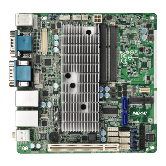
CPU_FAN1 Keyboard Mouse BLT_VOL1 COM1 COM2 VGA_H1 COM3 VGA1 SATA_PWR1 USB 2.0 T: USB1 RJ-45 B: USB0 PCIE1 IMB-147 USB 2.0 T: USB3 RJ-45 B: USB2 USB_4_5 LPT1 USB_6_7 PANEL 1 PLED PWRBTN PWR_JP1 HDLED RESET COM_PWR4 AUDIO 16Mb BUZZ1... - Page 10 Backlight & Amp Volume Control Header (BLT_VOL1) LVDS Panel Connector (LVDS1) Panel Power Jumper (PNL_PWR1) Inverter Power Control Header (BLT_PWR3) CPU FAN Connector (CPU_FAN1) Chassis FAN Connector (CHA_FAN1) ATX 12V Power Connector (DC12V1) SATA Power Connector (SATA_PWR1) Half-size mini PCIE Connector (PCIE1) SATA2 Connector (SATA2_1) SATA2 Connector (SATA2_2) System Panel Header (PANEL1)
-
Page 11: I/O Panel
1.5 I/O Panel PS2 Mouse Port (Green) COM Port (COM2) COM Port (COM3) LAN RJ-45 Port LAN RJ-45 Port Front Speaker (Lime) Microphone (Pink) USB 2.0 Ports (USB23) USB 2.0 Ports (USB01) VGA Port (VGA1) COM Port (COM1) PS2 Keyboard Port (Purple) * There are two LEDs on each LAN port. -
Page 12: Installation
Chapter 2: Installation This is a Mini-ITX form factor motherboard. Before you install the mother- board, study the configuration of your chassis to ensure that the mother- board fits into it. Pre-installation Precautions Take note of the following precautions before you install motherboard com- ponents or change any motherboard settings. -
Page 13: Installing Memory Modules (Dimm)
2.1 Installing Memory Modules (DIMM) This motherboard provides two 204-pin DDR3 (Double Data Rate 3) SO- DIMM slots. Step 1. Align a DIMM on the slot such that the notch on the DIMM matches the break on the slot. The DIMM only fits in one correct orientation. It will cause per- manent damage to the motherboard and the DIMM if you force the DIMM into the slot at incorrect orientation. -
Page 14: Expansion Slots (Pci And Pci Express Slots)
2.2 Expansion Slots (PCI and PCI Express Slots) There is 1 PCI slot and 1 mini PCI Express slot on this motherboard. PCI Slot: PCI slot is used to install expansion cards that have the 32-bit PCI interface. mini-PCIE Slot: mini_PCIE1 is used for mini PCIE cards. Installing an Expansion Card Step 1. -
Page 15: Installing Sata Hard Disks
2.3 Installing Serial SATA / SATA2 Hard Disks STEP 1: Connect the SATA power cable to the hard disk. STEP 2: Connect one end of the SATA data cable to the hard disk. STEP 3: Connect the other end of the SATA data cable to the mother- board’s SATA2 connectors. -
Page 16: Power Connectors
2.4 Power Connectors ATX 12V Power Connector Please connect a power supply to this connector. (4-pin ATX12V1) (see p.10, No. 7) SATA Power Connector Please connect a SATA (4-pin SATA_PWR1) power cable. (see p.10, No. 8) +12V... -
Page 17: Installing The System Panel
2.5 Installing the System Panel Connect the power switch, reset switch and system status indicator on the chassis to this header according to the pin assignments below. Note the positive and negative pins before connecting the cables. PWRBTN (Power Switch): Connect to the power switch on the chassis front panel. -
Page 18: Onboard Headers And Connectors
2.6 Onboard Headers and Connectors Onboard headers and connectors are NOT jumpers. Do NOT place jumper caps over these headers and connectors. Plac- ing jumper caps over the headers and connectors will cause permanent damage to the motherboard! USB 2.0 Headers Besides four default USB 2.0 ports on the I/O panel, there (8-pin USB_4_5) - Page 19 Serial Port Header PIN Signal Name PIN Signal Name (10-pin COM4) COM VOLT (see p.10, No. 19) (10-pin COM5) (see p.10, No. 20) (10-pin COM6) (see p.10, No. 21) RS232 RS422 RS485 DCD, Data RTX+ carrier detect RXD, Receive data TXD, Transmit RTX- data...
- Page 20 Inverter Power Control Signal Name Connector +12V (5-pin BLT_PWR3) (see p.10, No. 4) B/L ENABLE B/L ADJUST Backlight & Amp Signal Name Volume Control VOL_UP Header VOL_DW (7-pin BLT_VOL1) BKT_OFF (see p.10, No. 1) BKT_UP BKT_DW GPIO& Header PIN Signal Name PIN Signal Name (10-pin DGIO_AMP1) SMB_DATA SMB_CLK...
- Page 21 VGA Header PIN Signal Name PIN Signal Name (10-pin VGA_H1) (see p.10, No. 28) BLUE HSYNC VSYNC DDC_CLK DDC_DAT...
-
Page 22: Jumpers Setup
2.7 Jumpers Setup The illustration shows how jumpers are setup. When the jumper cap is placed on the pins, the jumper is “Short”. If no jumper cap is placed on the pins, the jumper is “Open”. The illustration shows a 3-pin jumper whose pin1 and pin2 are “Short”... - Page 23 Panel Power Jumper 1-2 : +3V (3-pin PNL_PWR1) 2-3 : +5V (see p.10, No. 3) ATX/AT Mode Jumper 1-2 : AT Mode 2-3 : ATX Mode (3-pin PWR_JP1) (see p.10, No. 13)
-
Page 24: Operating System Setup
2.8 Operating System Setup ® ® This motherboard supports Microsoft Windows 7. Because motherboard settings and hardware options vary, use the setup procedures in this chap- ter for general reference only. Refer your OS documentation for more infor- mation. ® 2.8.1 Installing Windows 7 without RAID Using AHCI Mode... -
Page 25: Installing Drivers
Click on a specific item then follow the installation wizard to install it. 2.9.4 Contact Information If you need to contact ASRock or want to know more about ASRock, you’re welcome to visit ASRock’s website at http://www.asrock.com; or you may contact your dealer for further information. -
Page 26: Hot Plug For Hard Disk Drives
2.10 Hot Plug for Hard Disk Drives This motherboard supports Hot Plug for SATA2 in AHCI mode. What is Hot Plug? If the HDDs are NOT set for RAID, it is called “Hot Plug” for the action to insert and remove the HDDs while the system is still powered on and in working condition. - Page 27 * Hot Plug might not be supported by the chipset because of its limitation. The support information of our motherboards are indicated in the product spec on our website: www.asrock.com 4. Make sure your HDDs can support Hot Plug from your dealer or HDD user manual.
- Page 28 How to Hot Plug an HDD: Please follow the instructions below to process Hot Plug. Improper procedures will cause the HDD damage and data loss. Please connect the SATA power Connect the SATA data cable Step 2 Step 1 cable’s 1x4-pin end (White) to to the motherboard’s SATA the power supply’s 1x4-pin cable.
- Page 29 How to Hot Unplug an HDD: Please follow the instructions below to process Hot Unplug. Improper procedures will cause the HDD damage and data loss. Step 1 Unplug the SATA data cable from the HDD’s side. Step 2 Unplug the SATA 15-pin power cable connector (Black) from the HDD's side.
-
Page 30: Uefi Setup Utility
Chapter 3: UEFI SETUP UTILITY 3.1 Introduction This section explains how to use the UEFI SETUP UTILITY to configure your system. The UEFI chip on the motherboard stores the UEFI SETUP UTILITY. You may run the UEFI SETUP UTILITY when you start up the computer. -
Page 31: Navigation Keys
3.1.2 Navigation Keys Use < > key or < > key to choose among the selections on the menu bar, and use < > key or < > key to move the cursor up or down to select items, then press <Enter> to get into the sub screen. You can also use the mouse to click your required item. -
Page 32: Main Screen
3.2 Main Screen When you enter the UEFI SETUP UTILITY, the Main screen will appear and display the system overview. -
Page 33: Advanced Screen
3.3 Advanced Screen In this section, you may set the configurations for the following items: CPU Configuration, Chipset Configuration, Storage Configuration, Super IO Configuration, ACPI Configuration and USB Configuration. Setting wrong values in this section may cause the system to malfunction. Instant Flash Instant Flash is a UEFI flash utility embedded in Flash ROM. -
Page 34: Cpu Configuration
3.3.1 CPU Configuration Hyper-Threading To enable this feature, a computer system with an Intel processor that supports Hyper-Threading technology and an operating system ® that includes optimization for this technology such as Microsoft ® Windows XP / Vista / 7 / 8 is required. Set to [Enabled] if using ®... -
Page 35: Chipset Configuration
3.3.2 Chipset Configuration Panel Type Selection Use this to select a panel type. Display Boot Type Use this to select the video device which will be activated during POST. ACPI HPET Table Use this to enable or disable the ACPI HPET Table. Restore on AC/Power Loss This allows you to set the power state after an unexpected AC/ power loss. -
Page 36: Storage Configuration
3.3.3 Storage Configuration Onboard SATAII Mode Use this to select the SATA mode for SATA2_1 and SATA2_2 ports. Configuration options: [IDE Mode] and [AHCI Mode]. Hard Disk S.M.A.R.T. Use this to enable or disable S.M.A.R.T. (Self-Monitoring, Analysis, and Reporting Technology). -
Page 37: Super Io Configuration
3.3.4 Super IO Configuration COM1 Port Use this to enable or disable COM1 port. COM1 Port Address Use this to set the address for COM1 port. COM2 Port Use this to enable or disable COM2 port. COM2 Port Address Use this to set the address for COM2 port. COM3 Port Use this to enable or disable COM1 port. - Page 38 LPT1 Port Use this to enable or disable LPT1 port. LPT1 Port Mode Use this to set the mode for LPT1 port. LPT1 Port Address Use this to set the address for LPT1 port. WDT Timeout Reset This allows users to enable or disable the Watch Dog Timer timeout to reset the system.
-
Page 39: Acpi Configuration
3.3.5 ACPI Configuration Suspend to RAM Use this to select whether to auto-detect or disable Suspend-to- RAM. Select [Auto] to enable if the OS supports it. S3 Video Repost Use this to enable/disable S3 Video Repost. PS/2 Keyboard Power On Use this to enable or disable the PS/2 keyboard to turn on the sys- tem from power-soft-off mode. -
Page 40: Usb Configuration
3.3.6 USB Configuration USB 2.0 Controller Use this to enable or disable the USB 2.0 controller. Legacy USB Support Use this to select legacy support for USB devices. There are four configuration options: [Enabled], [Auto], [Disabled] and [UEFI Setup Only]. The default value is [Enabled]. Please refer to the descrip- tions below for details of these four options: [Enabled] - Enables support for legacy USB. -
Page 41: Hardware Health Event Monitoring Screen
3.4 Hardware Health Event Monitoring Screen This section allows you to monitor the status of the hardware on your sys- tem, including the parameters of the CPU temperature, motherboard tem- perature, fan speed and voltage. CPU FAN1 Setting This allows you to set CPU FAN1’s speed. Configuration options: [Full On] and [Automatic Mode]. -
Page 42: Boot Screen
3.5 Boot Screen This section displays the available devices on your system for you to con- figure the boot settings and the boot priority. Setup Prompt Timeout This shows the number of seconds to wait for the setup activation key. Bootup Num-Lock If this is set to [On], it will automatically activate the Numeric Lock after boot-up. -
Page 43: Security Screen
3.6 Security Screen In this section you may set or change the supervisor/user password for the system. You may also clear the user password. -
Page 44: Exit Screen
3.7 Exit Screen Save Changes and Exit When you select this option the following message, “Save configu- ration changes and exit setup?” will pop out. Select [OK] to save changes and exit the UEFI SETUP UTILITY. Discard Changes and Exit When you select this option the following message, “Discard changes and exit setup?”...