ASROCK IMB-156 User Manual
Hide thumbs
Also See for IMB-156:
- Jumpers and headers setting manual (2 pages) ,
- Settings manual (2 pages) ,
- User manual (37 pages)

Related Manuals for ASROCK IMB-156


Summary of Contents for ASROCK IMB-156
- Page 1 IMB-156 User Manual Version 1.0 Published March 2017 Copyright©2017 ASRock INC. All rights reserved.
- Page 2 (including damages for loss of profits, loss of business, loss of data, interruption of business and the like), even if ASRock has been advised of the possibility of such damages arising from any defect or error in the documentation or product.
- Page 3 The terms HDMI™ and HDMI High-Definition Multimedia Interface, and the HDMI logo are trademarks or registered trademarks of HDMI Licensing LLC in the United States and other countries. CAUTION: RISK OF EXPLOSION IF BATTERY IS REPLACED BY AN INCORRECT TYPE. DISPOSE OF USED BATTERIES ACCORDING TO THE INSTRUCTIONS.
-
Page 4: Table Of Contents
Contents 1 Introduction ............5 1.1 Package Contents ............5 1.2 Specifications ..............6 1.3 Motherboard Layout ............8 1.4 I/O Panel ................ 10 2 Installation ............11 2.1 Screw Holes ..............11 2.2 Pre-installation Precautions ........... 11 2.3 Installation of Memory Modules (SO-DIMM) ....12 2.4 Expansion Slot ............... -
Page 5: Introduction
In case any modifications of this manual occur, the updated version will be available on ASRock website without further notice. You may find the latest VGA cards and CPU support lists on ASRock website as well. ASRock website http://www.asrock.com If you require technical support related to this motherboard, please visit our website for specific information about the model you are using. -
Page 6: Specifications
1.2 Specifications Form Dimensions Mini-ITX (6.7-in x 6.7-in) Factor ® BGA1296 for Intel Apollo Lake SoC Core (By CPU, Max 4) Number Processor Max Speed (By CPU) System L2 Cache (By CPU) Chipset BIOS UEFI 1 (half/full size, supports PCIe x1 and USB Mini-PCIe (shared)) 2 (1 x M2_1 Slot (Key M) supporting type... - Page 7 HDMI DisplayPort 0 Rear I/O Ethernet 4 x USB 3.0 Audio 2 (Mic-in, Line-out) Serial 3 x COM (Supports RS-232/422/485) PS/2 4 x USB 2.0 (2 x 2.54 pitch header) LVDS/ Inverter Serial 3 x COM (Supports RS-232 only) SATA mPCIe Internal Parallel...
-
Page 8: Motherboard Layout
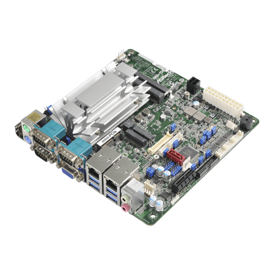
1.3 Motherboard Layout HDMI1 CPU_FAN1 EDP_LVDS_J2 DP_LVDS_J1 CLRMOS2 Port 1 Port 2 IMB-156 Industrial VGA1 mini-PCIe Port 3 VGA2 ATX12V1 USB 3.0 Top: T: USB1 LAN1 B: USB0 BLT_PWM1 BLT_PWR1 BLT_VOL1 USB 3.0 Top: USB6_S_MPCIE2 T: USB3 PNL_PWR1 BKT_PWR1 LAN2... - Page 9 1 : EDP_LVDS Jumpers (EDP_LVDS_J1, EDP_LVDS_J2) 2 : Clear CMOS Jumper 3 : 4-Pin CPU FAN Connector (+12V) 4 : ATX Power Connector (Input 12V-24V) 5 : LVDS Panel Connector 6 : BLT_PWM1 7 : BL1, BL2 8 : Backlight Volume Control (BLT_VOL1) 9 : Backlight Power Connector (BLT_PWR1) 10 : Panel Power Select (LCD_VCC) (PNL_PWR1) 11 : Digital Input / Output Power Select (JGPIO_PWR1)
-
Page 10: I/O Panel
1.4 I/O Panel PS/2 Mouse Port USB 3.0 Ports (USB3_2_3) COM Port 1 (COM1)* USB 3.0 Ports (USB3_0_1) COM Port 3 (COM3)* VGA Port (VGA1) LAN RJ-45 Port** COM Port 2 (COM2)* LAN RJ-45 Port** PS/2 Keyboard Port Line out (Green) HDMI Port (HDMI1) Microphone (Pink) * This motherboard supports RS232/422/485 on COM1~3 ports. -
Page 11: Installation
Chapter 2: Installation This is a Mini-ITX form factor (6.7" x 6.7", 17.0 x 17.0 cm) motherboard. Before you install the motherboard, study the configuration of your chassis to ensure that the motherboard fits into it. Make sure to unplug the power cord before installing or removing the motherboard. -
Page 12: Installation Of Memory Modules (So-Dimm)
2.3 Installation of Memory Modules (SO-DIMM) IMB-156 motherboard provides two 204-pin DDR3 (Double Data Rate 3) SO-DIMM slots, which support Dual Channel DDR3L (low voltage). 1. If you install one memory module only, please install it on DDR3_A1. 2. It is not allowed to install a DDR or DDR2 memory module into a DDR3 slot;... -
Page 13: Expansion Slot
2.4 Expansion Slots (mini-PCIe, PCI Express and M.2 Slots) There is 1 mini-PCIe slot, 1 PCI Express slot and 2 M.2 slots on this motherboard. mini-PCIe slot: MINI_PCIE1 (mini-PCIe slot; half/full size) is used for PCI Express mini cards. PCIE slot: PCIE1 (PCIE x1 slot) is used for PCI Express x1 lane width cards. M.2 slots: M2_1 Slot (Key M) supports type 2242/2260 M.2 SATA3 6.0 Gb/s module. -
Page 14: Jumpers Setup
2.5 Jumpers Setup The illustration shows how jumpers are setup. When the jumper cap is placed on pins, the jumper is “Short”. If no jumper cap is placed on pins, the jumper is “Open”. The illustration shows a 3-pin jumper whose pin1 and pin2 are “Short”... - Page 15 ATX/AT Mode Select 1-2: AT Mode 2-3: ATX Mode (3-pin PWR_JP1) (see p.8 No. 22) Panel Power Select (LCD_VCC) Use this to set up the VDD power of the LVDS connector. (5-pin PNL_PWR1) 1-2: LVDD: +3V (see p.8 No. 10) 2-3: LVDD: +5V 4-5: LVDD: +12V Backlight Power Select...
- Page 16 Digital Input / Output Default Value Setting 1-2: Pull-High 2-3: Pull-Low (3-pin JGPIO_SET1) (see p.8, No. 18) EDP_LVDS Jumpers 1-2: eDP 2-3: LVDS (3-pin EDP_LVDS_J1, EDP_LVDS_J2) (see p.8, No. 1) USB6_S_MPCIE1, USB6_S_MPCIE2 USB6_S_MPCIE1: Pin1 short USB2_4_5 pin4 and pin6 (2-pin USB6_S_MPCIE1, USB6_S_MPCIE2) short USB2_4_5 pin5: share USB port 5 (see p.8, No.
-
Page 17: Onboard Headers And Connectors
2.6 Onboard Headers and Connectors Onboard headers and connectors are NOT jumpers. Do NOT place jumper caps over these headers and connectors. Placing jumper caps over the headers and connectors will cause permanent damage of the motherboard! SATA3 Connector This Serial ATA3 (SATA3) connector supports (SATA3_1: see p.8, No. - Page 18 PLED (System Power LED): Connect to the power status indicator on the chassis front panel. The LED is on when the system is operating. The LED keeps blinking when the sys- tem is in S1 sleep state. The LED is off when the system is in S3/S4 sleep state or powered off (S5).
- Page 19 Chassis Fan Connector Please connect the fan cable to the fan connector and (4-pin CHA_FAN1) +12V match the black wire to the (see p.8 No. 15) FAN_SPEED FAN_SPEED_CONTROL ground pin. CPU Fan Connector Please connect the CPU fan FAN_SPEED_CONTROL FAN_SPEED cable to the connector and (4-pin CPU_FAN1) +12V...
- Page 20 LVDS Connector (40-pin LVDS1) (see p.8 No. 5) Backlight Volume Control Signal Name GPIO_VOL_UP (7-pin BLT_VOL1) GPIO_VOL_DW (see p.8 No. 8) PWRDN LVDS1 BLUP LVDS1 BLDW Backlight Power Connector Signal Name (6-pin BLT_PWR1) (see p.8 No. 9) BL CTL BL EN LCD_BLT_VCC LCD_BLT_VCC SATA Power Output Connector...
- Page 21 COM4, 5, 6 Headers (RS232) (10-pin COM4/COM5/COM6: see p.8, No. 17) Signal Signal Signal Signal Signal Name Name Name Name Name DDCD# TTXD RRTS# RRXD DDTR# DDSR# CCTS# +12V LPC Header This connector supports a Trusted Platform Module (TPM) (19-pin LPC1) system, which can see p.8, No.
-
Page 22: Uefi Setup Utility
Chapter 3: UEFI SETUP UTILITY 3.1 Introduction This section explains how to use the UEFI SETUP UTILITY to configure your system. The UEFI chip on the motherboard stores the UEFI SETUP UTILITY. You may run the UEFI SETUP UTILITY when you start up the computer. Please press <F2>... -
Page 23: Navigation Keys
3.1.2 Navigation Keys Please check the following table for the function description of each navigation key. Navigation Key(s) Function Description Moves cursor left or right to select Screens Moves cursor up or down to select items + / - To change option for the selected items <Enter>... -
Page 24: Advanced Screen
3.3 Advanced Screen In this section, you may set the configurations for the following items: CPU Configu- ration, Chipset Configuration, Storage Configuration, Super IO Configuration, ACPI Configuration and USB Configuration. Setting wrong values in this section may cause the system to malfunction. Instant Flash Instant Flash is a UEFI flash utility embedded in Flash ROM. -
Page 25: Cpu Configuration
3.3.1 CPU Configuration Intel SpeedStep Technology Intel SpeedStep technology is Intel’s new power saving technology. Pro- cessors can switch between multiple frequencies and voltage points to en- able power saving. The default value is [Enabled]. Configuration options: ® [Enabled] and [Disabled]. If you install Windows OS and want to enable this function, please set this item to [Enabled]. -
Page 26: Chipset Configuration
3.3.2 Chipset Configuration DRAM Frequency If [Auto] is selected, the motherboard will detect the memory module(s) inserted and assign the appropriate frequency automatically. Primary Graphics Adapter This allows you to select [Onboard] or [PCI Express] as the boot graphic adapter priority. The default value is [PCI Express]. Share Memory Configure the size of memory that is allocated to the integrated graphics processor when the system boots up. -
Page 27: Storage Configuration
3.3.3 Storage Configuration SATA Controller(s) Use this item to enable or disable the SATA Controller feature. SATA Mode Selection Use this to select SATA mode. Configuration options: [IDE Mode], [AHCI Mode] and [Disabled]. The default value is [AHCI Mode]. AHCI (Advanced Host Controller Interface) supports NCQ and other new features that will improve SATA disk perfor- mance but IDE mode does not have these advantages. -
Page 28: Super Io Configuration
3.3.4 Super IO Configuration Serial Port1 Use this to enable or disable COM1. Type Select Use this to select COM1 port type: [RS232], [RS422] or [RS485]. Serial Port2 Use this to enable or disable COM2. Type Select Use this to select COM2 port type: [RS232], [RS422] or [RS485]. Serial Port3 Use this to enable or disable COM3. - Page 29 WDT Timeout Reset This allows users to enable/disable the Watch Dog Timer timeout to reset system. The default value is [Disabled].
-
Page 30: Acpi Configuration
3.3.5 ACPI Configuration Suspend to RAM Use this item to select whether to auto-detect or disable the Suspend-to- RAM feature. Select [Auto] will enable this feature if the OS supports it. ACPI HPET Table Use this item to enable or disable ACPI HPET Table. The default value is [Enabled]. -
Page 31: Usb Configuration
3.3.6 USB Configuration Legacy USB Support Use this option to select legacy support for USB devices. There are four configuration options: [Enabled], [Auto] and [UEFI Setup Only]. The default value is [Auto]. Please refer to below descriptions for the details of these four options: [Enabled] - Enables support for legacy USB. -
Page 32: Hardware Health Event Monitoring Screen
3.4 Hardware Health Event Monitoring Screen In this section, it allows you to monitor the status of the hardware on your system, including the parameters of the CPU temperature, motherboard temperature, CPU fan speed, chassis fan speed, and the critical voltage. CPU_FAN1 Setting This allows you to set CPU_FAN1’s speed. -
Page 33: Security Screen
3.5 Security Screen In this section, you may set, change or clear the supervisor/user password for the system. Supervisor Password Set or change the password for the administrator account. Only the ad- ministrator has authority to change the settings in the UEFI Setup Utility. Leave it blank and press enter to remove the password. -
Page 34: Boot Screen
3.6 Boot Screen In this section, it will display the available devices on your system for you to config- ure the boot settings and the boot priority. Boot From Onboard LAN Use this item to enable or disable the Boot From Onboard LAN feature. Setup Prompt Timeout This shows the number of seconds to wait for setup activation key. - Page 35 CSM (Compatibility Support Module) Enable to launch the Compatibility Support Module. Please do not disable unless you’re running a WHCK test. If you are using Windows 8 / 8.1 64- bit and all of your devices support UEFI, you may also disable CSM for faster boot speed.
-
Page 36: Exit Screen
3.7 Exit Screen Save Changes and Exit When you select this option, it will pop-out the following message, “Save configuration changes and exit setup?” Select [OK] to save the changes and exit the UEFI SETUP UTILITY. Discard Changes and Exit When you select this option, it will pop-out the following message, “Discard changes and exit setup?”... -
Page 37: Software Support
Click on a specific item then follow the installation wizard to install it. 4.2.4 Contact Information If you need to contact ASRock or want to know more about ASRock, you’re welcome to visit ASRock’s website at http://www.asrock.com; or you may con-...