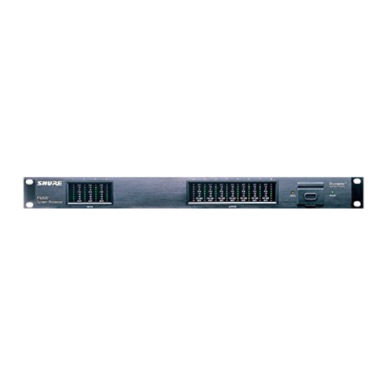
Summary of Contents for Shure P4800
- Page 1 Model P4800 System Processor Installation Guide 2007, Shure Incorporated Printed in U.S.A. Patent No. 5,999,631 27B8695 (Rev. 3)
-
Page 2: Packing List
User Interface, processors can be placed anywhere in the signal path. The 4-by-8 matrix mixer allows any or all inputs to be routed to any or all outputs with additional controls for levels and polarity. The P4800 can store up to 128 configurations that can be recalled using simple contact closures, MIDI, or RS232 commands. - Page 3 Operating the P4800 software simultaneously with programs such as SIA–Smaart or Gold Line TEFt requires a faster processor and more RAM. The following table lists the minimum requirements for running the P4800 software with no other applications in the background, including virus protection, firewall, instant messaging, or email.
-
Page 4: Audio Connections
ENGLISH AUDIO CONNECTIONS NOTE: The P4800 ships with a blank configuration. Audio will not pass from the inputs to the outputs until it has been configured to do so through the computer interface. Wiring Connectors Analog Inputs and Outputs Block Connector Terminal... - Page 5 Up to 16 ShureLink devices, including P4800s, DP11EQs, DFR11EQs, and UA888s can be linked and controlled from one computer. Connect the ShureLink IN and ShureLink OUT of each device using 5-pin DIN cables (like the one supplied with the P4800), as shown in Figure 6.
- Page 6 NOTE: Control pins must be configured to match the attached control hardware using the P4800 software (Refer to the Control Pin section of the online help or the online user guide included on the P4800 CD ROM).
-
Page 7: Processor Control
Logic Output Pins Processor Logic Output Figure 11 shows examples of how to wire Logic Output pins to LEDs or relays. You can then configure the P4800 to ground the ap- propriate pins to reflect muted channels. *Necessary for LEDs 5V dc Relay not rated for 5V. -
Page 8: Midi Control
Figure 12 MIDI CONTROL MIDI Connectors The MIDI port on the P4800 allows you to use a MIDI controller to change presets and perform other P4800 functions. For ex- ample, a standard MIDI message for PROGRAM CHANGE would cause a preset change in a device. The message must contain the Device ID and the number of the desired preset. -
Page 9: Specifications
AMX/CRESTRON CONTROL The P4800 uses a standard 7 wire RS–232 port for control. Crestron and AMX controllers use 5 wire RS–232. In order to use a P4800 with Crestron or AMX system, you will need to build a custom cable. Refer to the following diagram for wiring instructions. -
Page 10: Information To User
At its option Shure will repair or replace the defective product and promptly return it to you, or refund the purchase price. You should retain proof of purchase to validate the purchase date and return it with any warranty claim. - Page 11 United States, Canada, Latin America, Caribbean: 5800 W. Touhy Avenue, Niles, IL 60714-4608, U.S.A. Phone: 847-600-2000 U.S. Fax: 847-600-1212 Intl Fax: 847-600-6446 Europe, Middle East, Africa: Shure Europe GmbH, Phone: 49-7131-72140 Fax: 49-7131-721414 Asia, Pacific: Shure Asia Limited, Phone: 852-2893-4290 Fax: 852-2893-4055...


