Table of Contents
Advertisement
Available languages
Available languages
Quick Links
Installation and Operating Instructions
MANUAL TRANSFER SWITCH MODELS 6375 and 6377
®
WARNING: Generac
transfer switches should be installed by a professional electrician familiar with electrical wiring and codes, and experienced in working with generators. Generac
accepts no responsibility for accidents, damages or personal injury caused by incorrect installation. This transfer switch is intended for surface mounting OUTDOORS only. Our transfer
switches are UL listed to UL 1008 and meet the criteria of National Electrical code Article 702.6 for Optional Standby Systems. CAUTION: If using the generator and transfer switch for
larger appliances, such as electric water heaters, clothes dryers, electric ranges and small air conditioners, check the labels on the appliances to be sure they do NOT exceed the rating
of the generator. No appliance should have an amperage rating that exceeds the individual breaker rating in the transfer switch (20 or 30 amps). CALIFORNIA PROPOSITION 65
WARNING: Engine exhaust and some of its constituents are known to the State of California to cause cancer, birth defects and other reproductive harm. This product may contain or
emit chemicals known to cause cancer, birth defects and other reproductive harm.
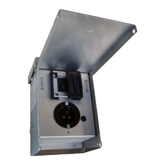
Model 6375 Shown
TABLE 1 - SPECIFICATIONS
MODEL:
Max Generator Size in Watts
Max Amps
NEMA Configuration of Power Inlet
Voltage
NEMA Type Enclosure
Phase
Minimum Gauge Cord Size
STEP 1: INSTALLATION PROCEDURE:
HAZARDOUS VOLTAGES ARE PRESENT INSIDE TRANSFER SWITCH ENCLOSURES THAT CAN CAUSE DEATH OR SEVERE PERSONAL INJURY. FOLLOW PROPER INSTALLATION,
OPERATION AND MAINTENANCE PROCEDURES TO AVOID HAZARDOUS VOLTAGES. TURN OFF THE MAIN CIRCUIT BREAKER IN THE LOAD CENTER BEFORE STARTING INSTALLATION.
Model 6375 – 15 amp Furnace Transfer Switch
1.
Furnace transfer switch can be installed to the left or right side of load center. See Figure 3. Trial fit the unit, holding up to the wall about 18" from the
center of the load center, and mark the location of the transfer switch and end of harness at load center.
2.
Remove the load center cover. CAUTION: dangerous voltages present inside load center. Locate and remove a ½" KO from the bottom of the load
center where marked in Step 1. Insert harness wires from transfer switch thru KO and install conduit fitting.
3.
Remove and retain the two screws that secure interior assembly to the transfer switch enclosure.
4.
Lift and pull out interior assembly to provide access to the four (4) mounting holes at the back of the enclosure. Mount transfer switch enclosure in
desired position using installer-provided fasteners through the four (4) mounting holes in back of enclosure. Re-install interior assembly into enclosure
(be sure not to pinch any wires between the enclosure and interior assembly) by hooking the top of the interior assembly deadfront over the studs on
the inside of the enclosure and securing the interior assembly to the enclosure with the two screws removed in Step 3. You are now ready to connect
the transfer switch wires to the desired circuit inside the load center.
5.
Turn OFF the circuit breaker in the load center that you want to connect to the transfer switch. Loosen the screw that secures the wire into the circuit
breaker and remove the wire from the circuit breaker.
6.
Insert the RED (UTIL) wire from the transfer switch into the circuit breaker and tighten screw.
7.
Using a wire connector, connect the wire removed from the circuit breaker in step 5 with the BLACK (LOAD) wire coming from the transfer switch.
8.
Insert and tighten the WHITE (neutral) wire from the transfer switch into the NEUTRAL bar in the load center. Insert and tighten the GREEN (ground)
wire from the transfer switch into the GROUND bar in the load center. If there is no ground bar, insert and tighten it into the NEUTRAL bar.
9.
Reinstall load center cover. Turn on circuit breaker turned off in step 5. Transfer switch is now ready for testing and operation.
Thank you for purchasing a Generac Transfer Switch to safely connect a portable
generator to a single circuit in your home or business (single phase only) for standby
power applications. Product features include:
Generator Main and Utility Mains mechanically interlocked to prevent utility and generator from
•
feeding circuit at the same time
This transfer switch is intended to be surface mounted next to an existing load center and wired to
•
one circuit breaker in the main panel.
Tools and Items Needed for Installation:
1/4" and 11/32 nut drivers
•
Straight blade and Phillips screwdriver
•
Electric drill, anchors and screws to mount transfer switch to wall
•
Wire cutter/stripper
•
Wire connectors
•
Power Cord to connect generator to switch
•
15 amps @ 125 volts
3R – Outdoor
1
6375
1875
5-15
125 Volts
1
12/3 AWG
6377
7500
30 amps @ 125/250 volts
L14-30
125/250 Volts
3R – Outdoor
1
10/4
Advertisement
Table of Contents

Related Manuals for Generac Power Systems 6375


Summary of Contents for Generac Power Systems 6375
- Page 1 WARNING: Generac transfer switches should be installed by a professional electrician familiar with electrical wiring and codes, and experienced in working with generators. Generac accepts no responsibility for accidents, damages or personal injury caused by incorrect installation. This transfer switch is intended for surface mounting OUTDOORS only. Our transfer switches are UL listed to UL 1008 and meet the criteria of National Electrical code Article 702.6 for Optional Standby Systems.
-
Page 2: Wiring Diagrams
Protected by US Patent No. US 6,861,596 B2 Generac Power Systems, Inc. Toll Free: 1-888-GENERAC www.generac.com 0196950SBY © 2012 Generac Power Systems, Inc. All Rights Reserved. GenTran and Generac are registered trademarks of Generac Power Systems, Inc. PN 50869 Rev A... -
Page 3: Étape 1 : Procédure D'installation
être installés par un électricien professionnel qui se connaît bien en câbles et codes électriques et a de l'expérience avec les génératrices. Generac décline toute responsabilité pour les accidents, les dommages ou les blessures causés par une installation incorrecte. Ce commutateur de transfert sera monté... - Page 4 A l'aide d'serre-fils, reliez le fil enlevé du disjoncteur dans l'étape 5 au fil NOIR (centre de distribution) venant du commutateur de transfert. Insérez et serrez le fil BLANC (neutre) du commutateur de transfert dans la barre de NEUTRE dans le centre de distribution. Insérez et serrez le fil VERT (de masse) du commutateur de transfert dans la barre de MASSE dans le centre de distribution.
-
Page 5: Étape 2 : Utilisation Du Commutateur De Transfert
Protégé par le brevet américain no. US 6.861.596 B2 Generac Power Systems, Inc. Numéro gratuit : 1-888-GENERAC www.generac.com © Generac 2012 Power Systems, Inc. Tous droits réservés. GenTran et Generac sont des marques déposées de Generac Power Systems, Inc. 50869 Rév. A... -
Page 6: Paso 1: Procedimiento De Instalación
Generac no acepta responsabilidad alguna por accidentes, daños o lesiones personales causadas por una instalación incorrecta. Este interruptor de transferencia está... -
Page 7: Diagramas De Cableado
Apague el disyuntor en el centro de carga al que desea conectar el conmutador de transferencia. Afloje el tornillo que fija el cable al disyuntor y quite el cable del disyuntor. Inserte el cable ROJO (UTIL) del conmutador de transferencia en el disyuntor y ajuste el tornillo. Con un conector de cables, conecte el cable que quitó... - Page 8 Protegido por la patente de los Estados Unidos N.° US 6,861,596 B2 Generac Power Systems, Inc. Línea gratuita: 1-888-GENERAC www.generac.com © 2012 Generac Power Systems, Inc. Todos los derechos reservados. GenTran y Generac son marcas registradas de Generac Power Systems, Inc. NP 50869 Rev. A...