Table of Contents
Advertisement
Available languages
Available languages
Quick Links
Installation and Operating Instructions
MANUAL TRANSFER SWITCH - MODELS 6295-6296 and 6378-6380
NOTE TO INSTALLER: Please leave this guide with the consumer for future reference. READ THIS MANUAL IN ITS ENTIRETY BEFORE ATTEMPTING TO INSTALL THIS EQUIPMENT.
®
WARNING: Generac
transfer switches should be installed by a professional electrician familiar with electrical wiring and codes, and experienced in working with generators. Generac accepts
no responsibility for accidents, damages or personal injury caused by incorrect installation. This transfer switch is intended for surface mounting INDOORS only. Our transfer switches are UL
listed to UL Standard 1008 and meet the criteria of National Electrical code Article 702.6 for Optional Standby Systems. CAUTION: If using the generator and transfer switch for larger
appliances, such as electric water heaters, clothes dryers, electric ranges and small air conditioners, check the labels on the appliances to be sure they do NOT exceed the rating of the
generator. No appliance should have an amperage rating that exceeds the individual breaker rating in the transfer switch. CALIFORNIA PROPOSITION 65 WARNING: Engine exhaust and some
of its constituents are known to the State of California to cause cancer, birth defects and other reproductive harm. This product may contain or emit chemicals known to cause cancer, birth
defects and other reproductive harm.
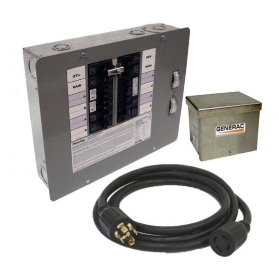
Model 6295 Kit Shown
What is Included in this Carton:
•
Manual Transfer Switch with wire harness, conduit, fittings and wire connectors (10 or 12)
•
Wire Harness, pre-assembled
•
30 amp or 50 amp Aluminum Power Inlet Box (Models 6295-6296 only)
•
10 Foot Power Cord (Models 6295-6296 only)
•
Installation Manual and Warranty Registration card
Tools and Items Needed for Installation:
•
1/4" nut driver, 2-1/8" hole saw (if flush mounting)
•
Screwdrivers, straight blade and Phillips
•
Electric drill, drill bits, wallboard saw
•
Wire cutter/stripper
•
Safety eye goggles
Anchors and screws to mount transfer switch to wall/wallboard
•
•
New, 2-pole 60 Amp or 100 Amp, 240V circuit breaker to install in main load center – same manufacturer as existing load center.
•
4 gauge building wire and conduit to connect between power inlet box and transfer switch
Compatible Circuit Breaker Types:
•
Siemens/Murray QT, QPH, HQP, QPF (GFCI), QPHF, QFP, QE, QEH, QAF (Arc Fault), QP (Surge Protector)
•
Cutler-Hammer Series BD, BR, BQ, GFC
•
Challenger Type A, C, HAGF
•
Square D Series HOM (Homeline)
•
GE Series THQL
Optional Items for Installation:
Arc-fault, GFCI or Surge protection circuit breakers. If Arc-fault, GFCI or Surge protection circuit breakers are used as the branch circuit protector in the main load
•
center, they MUST be used in the manual transfer switch. You may be able to re-use your existing AFCI, GFCI and Surge protection circuit breakers in the manual
transfer switch. See list of compatible breakers.
Wire, fittings and conduit to connect the Power Inlet Box to the transfer switch.
•
White, green, black and red THHN or MTW wire, 10 AWG, 300V rated (if breaker configuration is modified or expanded.
•
Switched Neutral Kit (SNK). If your portable generator has the neutral bonded to the frame of the generator AND 240V "full-power" receptacle is GFCI protected, you
•
will need to install a SNK accessory with your transfer switch to avoid nuisance tripping of the GFCI breaker on the generator.
Thank you for purchasing a Generac Transfer Switch to safely connect
a portable generator to the load center in your home or business
(single phase only) for standby power applications. Product features
include:
Generator and Utility feeds mechanically interlocked to prevent dangerous utility or
•
generator back feeding – thereby avoiding property damage and serious injury to
electrical workers.
Enclosure can be flush or surface mounted indoors.
•
Pre-assembled wire harness with all wires clearly marked for easy connection to
•
the load center.
Transfer switch can be expanded to up to 16 circuits using standard
•
interchangeable type circuit breakers. See Step 2, Section II.
Accommodates GFCI and Arc-Fault breakers to meet the latest NEC requirements.
•
Sufficient ground and neutral termination positions for all branch circuits
•
Subfeed lugs provided to feed additional downstream panels or to expand beyond
•
16 circuits.
Dual wattmeters help you monitor and balance the loads on your generator,
•
prolonging generator life.
Safe generator connection – Install the Power Inlet Box in a convenience location
•
outside for a quick cord connection to your generator.
Accepts a Switched Neutral Kit (SNK). See Page 2 Note on Neutral Bonded
•
Generators above Table 1.
1
Advertisement
Table of Contents

Related Manuals for Generac Power Systems GenTran 6295


Summary of Contents for Generac Power Systems GenTran 6295
- Page 1 WARNING: Generac transfer switches should be installed by a professional electrician familiar with electrical wiring and codes, and experienced in working with generators. Generac accepts no responsibility for accidents, damages or personal injury caused by incorrect installation. This transfer switch is intended for surface mounting INDOORS only. Our transfer switches are UL listed to UL Standard 1008 and meet the criteria of National Electrical code Article 702.6 for Optional Standby Systems.
-
Page 2: Step 1: Planning Your Installation
If it can be disabled, then no modifications to your transfer switch installation are needed. If the neutral bond cannot be disabled or voids the generator warranty, you must install a Switched Neutral Kit (SNK) accessory with your transfer switch. TABLE 1 - SPECIFICATIONS Model: 6295 or 6378 6296 or 6380 # Circuits Provided on Transfer Switch Max # Circuits... -
Page 3: Step 2: Installation Procedure
Install appropriately sized conduit, fittings and wire between the Power Inlet Box (Models 6295-6296 only) mounted on the building exterior and the transfer switch, referring to Power Inlet Box Install Instructions below. Locate and remove a KO on the right top or side of the transfer switch, pull wire into transfer switch enclosure and secure wire with fitting. -
Page 4: Step 3: Using Your Transfer Switch
C. Flush Mounting in Retrofit Construction (finished walls) Using Power Inlet Box (included in 6295-6296): Remove the dead front cover from the main load center and the transfer switch, save the screws. - Page 5 Protected by US Patent No. US 6,861,596 B2 Generac Power Systems, Inc. Toll Free: 1-888-GENERAC www.generac.com 0197000SBY © 2012 Generac Power Systems, Inc. All Rights Reserved. GenTran and Generac are registered trademarks of Generac Power Systems, Inc. PN 500508 Rev A...
- Page 6 être installés par un électricien professionnel qui se connaît bien en câbles et codes électriques et a de l'expérience avec les génératrices. Generac décline toute responsabilité pour les accidents, les dommages ou les blessures causés par une installation incorrecte. Ce commutateur de transfert sera monté...
-
Page 7: Étape 1 : Préparer L'installation
Si la connexion du neutre ne peut pas être désactivée ou si cela annule la garantie de la génératrice, vous devez installer l'accessoire appelé bloc neutre commuté (SNK) avec le commutateur de transfert. TABLEAU 1 - CARACTÉRISTIQUES Modèle : 6295 et 6378 6296 et 6380 Nombre de circuits disponibles sur le commutateur de transfert... -
Page 8: Étape 2 : Procédure D'installation
5. Décidez l'endroit où vous installerez la boîte d'entrée d'alimentation sur un mur extérieur à au moins 5 pieds de toute ouverture (portes, fenêtres, bouches d'aération, etc.). Voir la figure 1. TABLEAU 2 - FEUILLE DE TRAVAIL DU CIRCUIT No. du 6295 et 6378 6296 et 6380 APPAREIL OU CIRCUIT circuit ÉTAPE 2 : PROCÉDURE D'INSTALLATION :... - Page 9 une des entrées, au fond ou sur le côté, tenez le commutateur de transfert contre le mur sur lequel il sera monté, marquez les trous sur le mur pour les vis d'ancrage et fixez-le sur le mur (les ancrages ne sont pas fournis). Faites attention à ne pas contraindre le conduit flexible, car il peut casser. [NOTE : Le tube électrique non métallique (ENT) fourni est homologué...
-
Page 10: Étape 3 : Utilisation Du Commutateur De Transfert
III. INSTALLATION DE LA BOÎTE D'ENTRÉE D'ALIMENTATION (Modèles 6295-6296) Enlevez la couverture de la boîte d'entrée d'alimentation. Enlevez les 3 vis fixant l'entrée à bride sur la plaque inférieure. Pour les installations où les distances latérales dépassent 12 pouces des deux côtés, enlevez les 4 vis tenant la plaque inférieure accrochée à... - Page 11 Protégé par le brevet américain no. US 6.861.596 B2 Generac Power Systems, Inc. Numéro gratuit : 1-888-GENERAC www.generac.com © Generac 2012 Power Systems, Inc. Tous droits réservés. GenTran et Generac sont des marques déposées de Generac Power Systems, Inc. 500508 Rév. A...
- Page 12 Generac no acepta responsabilidad alguna por accidentes, daños o lesiones personales causadas por una instalación incorrecta. Este interruptor de transferencia está...
- Page 13 Si la unión neutral no puede quitarse o si invalida la garantía del generador, se debe instalar un accesorio de kit neutral con interruptor (SNK) con su interruptor de transferencia. TABLA 1: ESPECIFICACIONES Modelo: 6295 y 6378 6296 y 6380 Cantidad de circuitos incluidos en su interruptor de transferencia Cantidad máxima de circuitos...
-
Page 14: Paso 2: Procedimiento De Instalación
5. Determine dónde instalará la caja de entrada de cables eléctricos en una pared exterior al menos a 5 pies de distancia de las aberturas (puertas, ventanas, conductos de ventilación, etc.). Vea la Figura 1. TABLA 2: HOJA DE TRABAJO DE CIRCUITOS N.° DE CIRCUITO 6295 o 6378 6296 o 6380 APARATO O CIRCUITO PASO 2: PROCEDIMIENTO DE INSTALACIÓN: EXISTEN VOLTAJES PELIGROSOS DENTRO DE LAS CAJAS DEL INTERRUPTOR DE TRANSFERENCIA QUE PUEDEN CAUSAR LA MUERTE O DAÑOS PERSONALES GRAVES. - Page 15 I. INSTALACIÓN DEL INTERRUPTOR DE TRANSFERENCIA: A: Instalación con montaje en una superficie usando una caja de entrada de cables eléctricos (incluyendo en 6295-6296) Seleccione un lugar del lado izquierdo o derecho del centro de carga para montar el interruptor de transferencia, ya que se provee con un conducto flexible de 21.5".
- Page 16 III. INSTALAR LA CAJA DE ENTRADA DE CABLES ELÉCTRICOS (Incluyendo en Modelos 6295-6296) Retire la cubierta frontal de la caja de entrada de cables eléctricos. Retire los 3 tornillos que aseguran la entrada bridada a la placa inferior.
- Page 17 Protegido por la Patente de los Estados Unidos N.° US 6,861,596 B2 Generac Power Systems, Inc. Línea gratuita: 1-888-GENERAC www.generac.com © 2012 Generac Power Systems, Inc. Todos los derechos reservados. GenTran and Generac son marcas registradas de Generac Power Systems, Inc. PN 500508 Rev A...