Advertisement
Table of Contents
- 1 General Repair Information
- 2 Troubleshooting
- 3 Hydraulic Pump
- 4 Fan Belt
- 5 Pressure Control
- 6 Hydramax
- 7 Hydraulic Motor
- 8 Operation
- 9 Displacement Pump
- 10 Spray Gun
- 11 Hydramax Sprayers with Spray Gun and Hoses
- 12 Technical Data
- 13 Graco Phone Number
- 14 Graco Warranty
- Download this manual
See also:
Operation
REPAIR
This manual contains important
warnings and information.
READ AND KEEP FOR REFERENCE.
INSTRUCTIONS
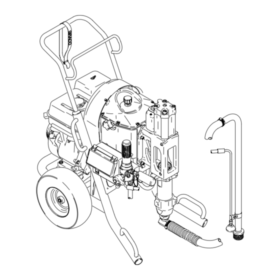
HydraMaxr Sprayers
HydraMax 225
3600 psi (248 bar, 24.8 MPa) Maximum Working Pressure)
Model
Series Direct
Immersion
233640
B
233641
B
233642
B
233643
B
HydraMax 300
3600 psi (248 bar, 24.8 MPa) Maximum Working Pressure)
Model
Series Direct
Immersion
233650
B
233651
B
HydraMax 350
4000 psi (276 bar, 27.6 MPa) Maximum Working Pressure)
Model
Series Direct
Immersion
233660
B
233661
B
Warnings
. . . . . . . . . . . . . . . . . . . . . . . . . . . . . . . . . . . . . .
General Repair Information
Maintenance
. . . . . . . . . . . . . . . . . . . . . . . . . . . . . . . . . . .
Troubleshooting
. . . . . . . . . . . . . . . . . . . . . . . . . . . . . . . .
Hydraulic Pump
. . . . . . . . . . . . . . . . . . . . . . . . . . . . . . . .
Fan Belt
. . . . . . . . . . . . . . . . . . . . . . . . . . . . . . . . . . . . . . .
Pressure Control
. . . . . . . . . . . . . . . . . . . . . . . . . . . . . . .
DTS Error Codes
. . . . . . . . . . . . . . . . . . . . . . . . . . . . . .
Engine
. . . . . . . . . . . . . . . . . . . . . . . . . . . . . . . . . . . . . . .
Displacement Pump
. . . . . . . . . . . . . . . . . . . . . . . . . . .
Hydraulic Motor
. . . . . . . . . . . . . . . . . . . . . . . . . . . . . . .
GRACO INC. P.O. BOX 1441 MINNEAPOLIS, MN 55440–1441
Parts
30 Gallon
RAC
Suction
Silver Gun
and Hose
X
X
X
X
30 Gallon
RAC X,
Suction
Silver Gun
and Hose
X
X
30 Gallon
GHD, Tex-
Suction
ture Gun
and Hose
X
X
Table of Contents
. . . . . . . . . . . . . . . . . . . . . .
ECOPYRIGHT 2001, GRACO INC.
Graco Inc. is registered to I.S. EN ISO 9001
R
X,
X
X
X
Related Manuals
Operation
Displacement Pump
Spray Gun
Spray Tip
AutoClean
Drain Valve
X
Board Repair Kit 244981
2
Directional Valve and Hydraulic Motor Switches
3
HydraMax 225 Sprayers Parts Drawing
4
HydraMax 225 Sprayers Parts List
5
HydraMax 300/350 Sprayers Parts Drawing
6
HydraMax 300/350 Sprayers Parts List
8
HydraMax 300/350 Sprayers Parts List
9
HydraMax Sprayers with Spray Gun and Hoses
11
Technical Data
12
Graco Phone Number
15
13
Graco Warranty
309379
. . . . . . . . . . . . . . . . . . . . . . . . . .
. . . . . . . . . . . . . . . . .
. . . . . . . . . . . . . . . . . . . . . . . . .
. . . . . . . . . . . . . . . . . . . . . . . . . . .
. . . . . . . . . . . . . . . . .
309380, 309278
. . . . . . . . . . . . . . . . . . . . . . . .
. . . . . . . . . . . . .
. . . . . . . . . . . . . . .
. . . . . . . . . . . . . . . . . . . . . . . . . . . . . . . .
. . . . . . . . . . . . . . . . . . . . . . . . . .
. . . . . . . . . . . . . . . . . . . . . . . . . . . . . . .
Rev. F
ti1431a
309378
309277
309740
309640
308961
309452
. . .
14
. . . . . . . . . . .
16
17
. . . . . . .
22
. . . . . . . . . . .
23
. . . . . . . . . . .
23
. . .
30
31
31
32
Advertisement
Table of Contents

Related Manuals for Graco HydraMax 225

Summary of Contents for Graco HydraMax 225
- Page 1 General Repair Information ..... . HydraMax 225 Sprayers Parts Drawing ...
- Page 2 ADVERTÊNCIA WARNING Perigo de incêndio e explosão: os solventes e os vapores da pintura Fire and explosion hazard: Solvent and paint fumes can ignite or poderão explodir ou incendiar. explode. Para ajudar a evitar incêndio e explosão: To help prevent a fire and explosion: DUtilize unicamente em áreas extremamente bem ventiladas.
-
Page 3: General Repair Information
General Repair Information WARNING WARNING MOVING PARTS HAZARD HOT SURFACES HAZARD To reduce risk of serious injury, do not EXPLOSION HAZARD touch moving parts with fingers or tools Hydraulic reservoir and engine may be while testing repair. Shut off sprayer very hot during operation and could burn when repairing. - Page 4 Maintenance DAILY: Check engine oil level and fill as necessary. WARNING DAILY: Check hydraulic oil level and fill as neces- INJECTION HAZARD sary. The system pressure must be manually relieved to prevent the system from DAILY: Check hose for wear and damage. starting or spraying accidentally.
-
Page 5: Troubleshooting
Troubleshooting WARNING INJECTION HAZARD To reduce risk of serious injury, when instructed to relieve pressure, follow steps 1. – 6.; page 4. PROBLEM CAUSE SOLUTION Gas engine pulls hard (won’t start) Hydraulic pressure is too high Turn hydraulic pressure knob ccw to lowest setting Gas engine will not start Switch OFF, low oil, no gasoline Consult engine manual, supplied... -
Page 6: Hydraulic Pump
Hydraulic Pump Removal 4. Fig 2. Set hydraulic pump (2) down and toward rear of reservoir to install. 5. Install two pump bolts (94) in reservoir with copper Relieve pressure; page 4. washers (64) on outside under screw heads. Torque to 31–35 ft-lb. Let hydraulic system cool before beginning ser- 6. - Page 7 Bottom View 6425 TI11476b Engine mounting fasteners Fig. 2 309379...
-
Page 8: Fan Belt
Fan Belt Removal Installation 1. Thread new belt around bottom drive pulley, and install on fan pulley. 1. Fig. 3. Remove two screws (141) and slide shroud (23) up and off of sprayer. a. lightly snug four engine fasteners. b. Loosen jam nut on belt tension adjustment 2. -
Page 9: Pressure Control
Pressure Control Display and Control Board Removal 6. Disconnect leads and remove control board (315). Installation Relieve pressure; page 4. 1. Install control board (315) (Manual 309452) and connect leads. 2. Fig. 4. Remove four screws (100) and pressure 2. Install six screws (72). control cover (99). - Page 10 Pressure Control Digital Tracking System (DTS) The DTS contains stored data to assist with job con- Lifetime Gallon Counter – Total material trol, troubleshooting and maintenance. pumped at all pressures over the lifetime of the sprayer. Counts in 1 gallon or 10 liter General increments.
- Page 11 DTS Error Codes No display does not mean that sprayer is not pressurized. Relieve pressure before repair; page 4. DISPLAY SPRAYER INDICATION ACTION OPERATION Engine runs. Pump stops. Pressure exceeded Correct over-pressure cause. 4900 psi (338 bar, 34 MPa) Check transducer and control board.
-
Page 12: Hydramax
Engine Removal 1. Do Fan Belt, Removal; page 8. 2. Fig. 5. Disconnect all necessary wiring. 3. Fig. 6. Remove four engine mounting fasteners from underside of engine. NOTE: All service to the engine must be performed by an authorized HONDA dealer. Belt Tension Adjustment Screw Only used on... -
Page 13: Hydraulic Motor
Hydraulic Motor Removal Installation 1. Install o-ring (44) and hydraulic cylinder (37), Relieve pressure; page 4. 2. Install cylinder sleeve (36). 2. Fig. 7. Remove four cap screws (33), washers (128) and cylinder cap (34). 3. Connect magnetic sensor (47). 3. - Page 14 Directional Valve and Hydraulic Motor Switches Directional Valve 2. Slide coil onto valve. Removal 3. Install large hex nut (F) on top of valve (32). Torque nut to 10 +/–1 ft-lb. Relieve pressure; page 4. 2. Fig. 7. Remove large hex nut (F) on top of Hydraulic Motor Switches valve (32).
-
Page 15: Operation
Displacement Pump See manual 309277 for pump repair instructions. Installation Removal WARNING 1. Flush pump. If pin works loose, parts could break off and project through the air and result in serious injury or prop- erty damage. Make sure pin is properly installed. Relieve pressure;... - Page 16 Parts Drawing – HydraMax 225 Sprayers Page 18 Page 20 Page 28 130a 130b ti1426C Apply anaerobic adhesive and torque to 190 – 210 in-lb 309379...
- Page 17 Parts List – HydraMax 225 Sprayers Models 233640 and 233641 Part No. Description Part No. Description 116080 ENGINE, 6.5 hp 104†* 189920 STRAINER 244949 PULLEY, gearbelt 198225 SHIELD, engine shaft includes 79, 80 108842 SCREW, cap, hex head 116399 WHEEL, pneumatic, 13”...
- Page 18 Parts Drawing – HydraMax 225 Sprayers Page 20 ti1427b 309379...
- Page 19 Parts List – HydraMax 225 Sprayers Models 233640 and 233641 Part No. Description Part No. Description 116068 PUMP, hydraulic 117241 SPRING 5ƒ 116060 FITTING, bulkhead, hydraulic 100016 WASHER, lock 116061 BELT, gearbelt, ’H’1/2 194317 LABEL, danger, English 13ƒ 110925 PACKING, o–ring...
- Page 20 Parts Drawing – HydraMax 225 Sprayers ti1428a ti1428a 309379...
- Page 21 Parts List – HydraMax 225 Sprayers Models 233640 and 233641 Part No. Description Part No. Description 244110 HOSE, coupled 102†* 108014 O-RING 244985 VALVE, directional 103* 105765 PACKING, o–ring 116375 SCREW, cap, socket head 276667 COVER, valve 197434 CAP, cylinder...
- Page 22 Parts Drawing – HydraMax 300/350 Sprayers Page 28 Apply anaerobic adhesive and torque to 190 – 210 in-lb ti1389C 309379...
- Page 23 Parts List – HydraMax 300/350 Sprayers Model 233650 and 233660 Part No. Description Part No. Description ENGINE 112958 116081 Model 300, 9.0 hp 198502 SPACER, mount, motor 116082 Model 350 11.0 hp 198206 SHIELD, engine shaft 243961 PULLEY, gearbelt 116645 SCREW, cap, hex head includes 79, 80 116739...
- Page 24 Parts Drawing – HydraMax 300/350 Sprayers Page 26 ti1390c 309379...
- Page 25 Parts List – HydraMax 300/350 Sprayers Model 233650 and 233660 Part No. Description Part No. Description PUMP, hydraulic 15A572 SPRING HOLDER 116699 Model 300 100004 SCREW, cap, hex hd 116700 Model 350 112958 116060 FITTING, bulkhead, hydraulic 116561 FITTING 116059 BELT, gearbelt, ’H’1/2 116996 SCREW, hex hd, flanged, 3/8–16...
- Page 26 Parts Drawing – HydraMax 300/350 Sprayers ti1391a 309379...
- Page 27 Parts List – HydraMax 300/350 Sprayers Model 233650 and 233660 Part No. Description Part No. Description 245201 HOSE, coupled 276667 COVER, valve 244985 VALVE, directional 106115 WASHER, lock 116376 SCREW, cap, socket head C19839 SCREW, shcs 196626 CAP, cylinder 116546 PLUG 196630 TUBE, hydraulic...
- Page 28 Parts Drawing – HydraMax 225/300/350 Sprayers 266G 15 Ref 76 Ref TI1430b WIRING DIAGRAM To Display Control Board To Engine 2 Pin Connector To Direction Value (32) 4 Pin Connector to Sensors (47) Black On/OFF 309379...
- Page 29 Parts List – HydraMax 225/300/350 Sprayers Model 233650 and 233660 Part No. Description Part No. Description 16‡ 243985 CABLE, power 244032 COVER, control 17‡ CABLE, power 100* 116252 SCREW 244946 Model 225 101* 198425 LABEL, GH, LCD 243986 Model 300/350...
-
Page 30: Spray Gun
HydraMax Sprayers with Spray Gun and Hoses HydraMax 225, 300 and 350 Sprayers Models 233642, 233643, 233651, 233661 Includes items 202 to 202f Part No. Description KIT, Hose and Gun 287043 Models 233642, 233643, 233651 244925 Model 233661 202a HOSE, 50 ft... -
Page 31: Technical Data
Technical Data Model Hydraulic Hydraulic Motor Cycles per Maximum Maximum Fluid Inlet Fluid Outlet Pressure Reservoir HP (kW) gallon (liter) Delivery Tip size psi (bar) Capacity gpm (lpm) Gallons (Liters) 1 gun 2 guns npsm(m) npt(f) 2035 2.75 6.5 (4.8) 47 (13) 2.25 (8.6) 0.050... -
Page 32: Graco Warranty
Graco Warranty Graco warrants all equipment listed in this manual which is manufactured by Graco and bearing its name to be free from defects in material and workmanship on the date of sale by an authorized Graco distributor to the original purchaser for use. With the exception of any special extended or limited warranty published by Graco, Graco will, for a period of twelve months from the date of sale, repair or replace any part of the equipment determined by Graco to be defective.