MTD Series 330 Operator's Manual
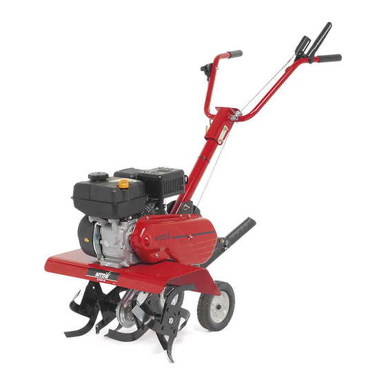
Front tine tiller
Hide thumbs
Also See for Series 330:
- Operator's manual (20 pages) ,
- Owner's manual (18 pages) ,
- Operator's manual (16 pages)
Advertisement
Quick Links
OPERATOR'S
MANUAL
Front Tine Tiller
Model Series
300 & 330
IMPORTANT:
READ SAFETY RULES AND INSTRUCTIONS
CAREFULLY
Warning:
This unit is equipped with an internal combustion engine and should not be used on or near any unimproved
forest_
covered, brush-covered
or grass-covered
land unless the engine's exhaust system is equipped with a spark arrester meeting
applicable local or state laws (if any). If a spark arrester is used, it should be maintained in effective working order by the operator.
In the State of California the above is required by law (Section 4442 of the California Public Resources Code). Other states may have
similar laws. Federal laws apply on federal lands. A spark arrester for the muffler is available through your nearest engine authorized
service dealer or contact the service department,
P.O. Box 361131 Cleveland, Ohio 44136-0019.
MTD LLC, P.O. BOX 361131 CLEVELAND,
OHIO 44136-0019
PRINTED IN U.S.A.
FORM NO. 770-10564
(11/2001 )
Advertisement

Related Manuals for MTD Series 330


Summary of Contents for MTD Series 330
- Page 1 Federal laws apply on federal lands. A spark arrester for the muffler is available through your nearest engine authorized service dealer or contact the service department, P.O. Box 361131 Cleveland, Ohio 44136-0019. MTD LLC, P.O. BOX 361131 CLEVELAND, OHIO 44136-0019 PRINTED IN U.S.A.
-
Page 2: Table Of Contents
TABLEOFCONTENTS Content Page Important Safe Operation Practices ..............Assembling Your Tiller ..................Know Your Tiller ....................Operating Your Tiller ..................Making Adjustments ..................Maintaining Your Tiller ..................Troubleshooting ....................Parts List ......................FINDINGMODEL NUMBER This Operator's Manual is an important part of your new Tiller. It will help you assemble, prepare and maintain the unit for best performance. -
Page 3: Important Safe Operation Practices
SECTION 1: IMPORTANT SAFEOPERATION P RACTICES WARNING: This symbol points out important safety instructions which, if not followed, could endanger the personal safety and/or property of yourself and others. Read and follow all instructions in this manual before attempting to operate this machine. Failure to comply with these instructions may result in personal injury. - Page 4 Look down andbehind andusecarewhen in Do not change the engine governor settings or over- reverse o rpulling m achine t owards y ou. speed the engine. The governor controls the 10. Start t heengine a ccording totheinstructions found maximum safe operating speed of the engine. inthismanual andkeep feetwell a way fromthe Maintain or replace safety and instruction labels, as tinesatalltimes.
-
Page 5: Assembling Your Tiller
SECTION 2: ASSEMBLING Y OUR TILLER NOTE: This operator's manual covers various models .Handle of tillers. The units illustrated may vary slightly from Adjustment Lever your unit. Follow only those instructions which pertain to your model number. NOTE: References to right or left side of the tiller are determined from behind the unit in the operating... -
Page 6: Know Your Tiller
CheckCableAdjustment With the clutch lever disengaged, pull starter rope slowly several times. The tines should not turn. If they turn, the cable is not adjusted properly. To adjust the cable, loosen the nut near the top of Clutch Lever_ the cable and unscrew the cable to provide additional slack in wire. -
Page 7: Operating Your Tiller
ChokeLever Engine Controls The choke lever is located near the throttle control. It is See the separate engine manual for additional used to enrich the fuel mixture when starting a cold information and functions of the engine controls. engine. StarterHandle The starter handle is located on the engine and is used to manually start the engine. - Page 8 ControllingSpeed AndTillingDepth Transport Position Wheel YokeAdjustment Place wheel yoke so that the wheels are forward (nearest point between wheels and tines) for shallow tilling, cultivating and transport. The forward speed will increase. Turn yoke around (farthest point between wheels and tines) for deep tilling. Forward speed will decrease.
-
Page 9: Making Adjustments
working width of the machine is 22 or 24 inches. For The tiller has many uses other than tilling and cultivation, this may be reduced to 13 inches by cultivating a garden. One of these is the preparation of removing the outer tines. Refer to the Adjustment lawn area for seeding. -
Page 10: Maintaining Your Tiller
SECTION 6: MAINTAINING YOUR TILLER Cleaning TineArea WARNING: Disconnect the spark plug wire and ground it against the engine Clean the underside of the tine shield after each use. before performing repairs The dirt washes off the tines easier if rinsed off maintenance. - Page 11 We do not recommend the use of pressure washers to clean your unit. They may cause damage to electric components, spindles, pulleys, -lex Screw bearings or the engine. The use of pressure washers will result in shortened life and reduce serviceability.
-
Page 12: Troubleshooting
SECTION 7: TROUBLESHOOTING Problem Cause Remedy Engine fails to start Spark plug wire disconnected. Connect wire to spark plug. Fuel tank empty or stale fuel. Fill tank with clean, fresh gasoline. Throttle control lever not in correct Move throttle lever to start position. starting position. - Page 13 Notes...
-
Page 14: Parts List
ModelSeries300 & 330 65"... - Page 15 ModelSeries300 & 330 Ref. Ref. Part No. Part No. Part Description Part Description 720-0274 712-3004A Flange Lock Nut 5/16-18 Grip 731-0473 Belt Cover Belt 711-0919 Clutch Grip 686-0002 Clutch Lever 710-0599 Hex Washer Screw 1/4-20 x .500 649-0137 786-0035A Tine Shield 20" Handle Assembly 712-0442 710-0502A...
- Page 16 ModelSeries300...
- Page 17 ModelSeries300 Ref. Ref. Part No. Part No. Part Description Part Description 734-1840 Wheel 7 x 1.7 736-0406 Flat Washer .442 ID x 1.38 OD 738-0929 Shoulder Screw 738-0843 Jack Shaft 686-0081A 613-0001A Wheel Bracket Assembly Sprocket Assembly 713-0312 714-0149B Cotter Pin Chain #420 x 46 Links 711-6415 Clevis Pin...
- Page 18 ModelSeries330...
- Page 19 ModelSeries330 Ref. Ref. Part No. Part No. Part Description Part Description 734-1781 Wheel 8 x 1.75 738-0843 Jack Shaft 738-0929 613-0001A Shoulder Screw Sprocket Assembly 686-0081A 713-0312 Chain #420 x 46 Links Wheel Bracket Assembly 714-0149B Cotter Pin 613-0003A Input Shaft Assembly 711-6415 Clevis Pin 750-0896...
- Page 20 MANUFACTURER'S LIMITED WARRANTY FOR: The limited warranty set forth below is given by MTD LLC MTD LLC does not extend any warranty for products with respect to new merchandise purchased and used in the sold or exported outside of the United States, its posses- United States.