MTD 300 series Shop Manual
Hide thumbs
Also See for 300 series:
- Operator's manual (53 pages) ,
- Owner's manual (20 pages) ,
- Operator's manual (20 pages)
Table of Contents
Advertisement
Professional Shop Manual
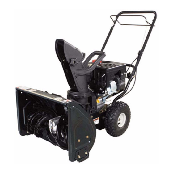
300 Series Snow Thrower
NOTE: These materials are for use by trained technicians who are experienced in the service and repair of outdoor power
equipment of the kind described in this publication, and are not intended for use by untrained or inexperienced individuals.
These materials are intended to provide supplemental information to assist the trained technician. Untrained or inexperi-
enced individuals should seek the assistance of an experienced and trained professional. Read, understand, and follow all
instructions and use common sense when working on power equipment. This includes the contents of the product's Oper-
ators Manual, supplied with the equipment. No liability can be accepted for any inaccuracies or omission in this publication,
although care has been taken to make it as complete and accurate as possible at the time of publication. However, due to
the variety of outdoor power equipment and continuing product changes that occur over time, updates will be made to these
instructions from time to time. Therefore, it may be necessary to obtain the latest materials before servicing or repairing a
product. The company reserves the right to make changes at any time to this publication without prior notice and without
incurring an obligation to make such changes to previously published versions. Instructions, photographs and illustrations
used in this publication are for reference use only and may not depict actual model and component parts.
© Copyright 2009 MTD Products Inc. All Rights Reserved
MTD Products Inc - Product Training and Education Department
FORM NUMBER - 769-05547
11/2009
Advertisement
Table of Contents

Related Manuals for MTD 300 series


Summary of Contents for MTD 300 series
- Page 1 Instructions, photographs and illustrations used in this publication are for reference use only and may not depict actual model and component parts. © Copyright 2009 MTD Products Inc. All Rights Reserved MTD Products Inc - Product Training and Education Department...
-
Page 3: Table Of Contents
The 300 series snow thrower ........ -
Page 5: Chapter 1: Introduction
• Common sense in operation and safety is assumed. • In no event shall MTD be liable for poor text interpretation, or poor execution of the procedures described in the text. • If the person using this manual is uncomfortable with any procedures they encounter, they should seek the... -
Page 6: Safety
INTRODUCTION Safety This Service Manual is meant to be used along with the Operator’s Manual. Read the Operator’s Manual and famil- iarize yourself with the safety and operational instructions for the equipment being worked on. Keep a copy of the Operator’s Manual for quick reference. -
Page 7: Fasteners
INTRODUCTION Fasteners • The fasteners used on the equipment described in this manual, and the engine that powers it are a combina- tion of metric and fractional inch. For this reason, wrench sizes are frequently identified in the text, and mea- surements are given in U.S. -
Page 8: Understanding Model And Serial Numbers
The model number of a the snow thrower described in this manual is 31A-32AD762. This manual is likely to carry useful information for a range of similar Snow Throwers that may carry a variety of MTD and private brand names. -
Page 9: Chapter 2: Maintenance
NOTE: If a shear pin breaks, the unique design of the augers on current MTD snow throwers allows the next auger over to continue driving the one with the broken shear pin. It is possible for a customer to continue clearing snow without noticing a damaged shear pin, but it will double the forces on the next shear pin. -
Page 10: Auger Drive System Maintenance
MAINTENANCE Spray penetrating oil on the joints between; • The auger shaft and the bearings in the auger housing that support it • the augers and the auger shaft • the augers and the shear pins • the impeller shaft and the impeller Check and adjust the shave plate and the skid shoes;... -
Page 11: Traction Drive System Maintenance
Maintenance Traction drive system maintenance NOTE: Be careful to keep oil and grease away from the belts and pulleys. NOTE: Replace any worn or damaged parts discovered during inspection. NOTE: If a part has failed prematurely, identify and correct the cause of the failure. Loosen the wheel bolts using a 1/2”... - Page 12 MAINTENANCE FINAL Reinstall the belt cover. Spray some penetrating oil into the points of the control cables where the cable core enters the cable housing. Re-fill the crankcase with fresh 5W-30 engine oil, and add a small amount of fresh gasoline to the fuel tank. Test-run the snow thrower, testing all operation and safety features.
-
Page 13: Chapter 3: Traction Drive System
If you encounter a snow thrower with ! CAUTION ! CAUTION plastic wheels, see Special Reminder Service Advisory MTD-098. NOTE: While it is possible to replace the tires on the Figure 3.1 wheels, they are generally serviced as an assembly. -
Page 14: Drive Belt Replacement: Single-Speed System
TRACTION DRIVE SYSTEM DRIVE BELT REPLACEMENT: SINGLE-SPEED SYSTEM Remove the belt cover: 1a. Remove the screw on the right side of the belt cover with a 5/16” wrench or screwdriver. See Figure 3.3. 1b. Squeeze the locking tabs on the belt cover inward while lifting. -
Page 15: Drive Belt Replacement: Three Speed Drive System
TRACTION DRIVE SYSTEM Rock the transmission forward to provide the slack needed to removed the drive belt from the transmission pulley. NOTE: The auger drive belt must be removed to remove or install the self-propel drive belt. See Figure 3.6. Slip the auger belt off of the front engine pulley sheave Route the drive belt between the upper and lower pulleys. - Page 16 TRACTION DRIVE SYSTEM Remove the spark plug and insert a 20” piece of starter rope to act as a piston stop and prevent the engine from turning. Auger drive pulley Remove the bolt that holds the auger drive pulley to the engine crankshaft with a 9/16”...
- Page 17 TRACTION DRIVE SYSTEM NOTE: .To replace the drive belt on a three speed drive Actuator arm system, the speed actuator arm needs to be removed. Loosen the jam nuts that hold the speed control cable to the Speed bracket on the engine. control Adjust the nuts to provide slack in the cable.
- Page 18 TRACTION DRIVE SYSTEM NOTE: A sealed ball bearing and the outer half of the vari- able speed pulley will come-off with it. Slip the belt off of the crankshaft. See Figure 3.16. Reach from under the snow thrower and pull the belt off of the transmission pulley.
-
Page 19: Drive Engagement Cable Replacement
TRACTION DRIVE SYSTEM DRIVE ENGAGEMENT CABLE REPLACEMENT Unhook the z-fitting from the drive engagement control bail: Right side: goes straight in 1a. Squeeze the bail to release the right side of the bail from the handlebar. 1b. Once the right side is released, pivot the bail to unhook the left side of it from the left handlebar. - Page 20 TRACTION DRIVE SYSTEM Release the cable from the transmission housing by squeezing the barbs that lock the cable housing into the bracket on the transmission. See Figure 3.22. Cable bracket Route the cable out of the frame. If the snow thrower has the three speed drive system; •...
-
Page 21: Speed Control Cable Replacement
TRACTION DRIVE SYSTEM SPEED CONTROL CABLE REPLACEMENT Remove the belt cover: 1a. Remove the screw on the right side of the belt cover with a 5/16” wrench or screwdriver. See Figure 3.23. 1b. Squeeze the locking tabs on the belt cover inward while lifting the cover. - Page 22 TRACTION DRIVE SYSTEM Remove the three phillips head screws that hold the cover Speed control on the speed control housing. See Figure 3.26. housing Figure 3.26 Carefully remove the speed control cable from the speed Speed control control housing. See Figure 3.27. cable •...
-
Page 23: Transmission Removal
TRACTION DRIVE SYSTEM TRANSMISSION REMOVAL Disconnect the z-fitting from the drive control on the handle bar. Detach the cable mounting block from the left side of the handle bars. Engage transmission Cut the cable retaining straps that secure the cable to the handle bars. - Page 24 TRACTION DRIVE SYSTEM Slide the bearing and shim out from each side of the frame. See Figure 3.32. Washer Inspect the bearings for wear or damage. Bearing NOTE: Apply a coating of grease to the shaft and bearing before reassembling. Out-put shaft Move the transmission to the left and pivot it forward to remove it from the frame.
-
Page 25: Transmission Internals
TRACTION DRIVE SYSTEM TRANSMISSION INTERNALS NOTE: the transmission has been broken down to satisfy professional curiosity, this information is not intended to suggest that the transmission is to be serviced. If you see any of these parts in the course of work- ing on a 300-series snow thrower, you have done something wrong. - Page 26 TRACTION DRIVE SYSTEM...
-
Page 27: Chapter 4: Auger System
AUGER SYSTEM CHAPTER 4: AUGER SYSTEM System Description • The auger and impeller are driven by a belt from the engine crankshaft. • An idler pulley is drawn against the belt when the control bale is engaged. • The belt then drives a large pulley on the back of the impeller shaft. •... - Page 28 AUGER SYSTEM Disconnect the auger control cable from the control bail. This will allow enough slack in the auger control cable to free the auger belt from the engine pulley. See Figure 4.3. Bail Cable Figure 4.3 Use your thumb to pull the auger brake far enough away from the auger pulley to slip the belt off of the pulley.
-
Page 29: Auger Control Cable Replacement
AUGER SYSTEM Auger control cable replacement Remove the belt cover as described in the “BELT Cable REMOVAL” section of this chapter. Cable guide Slip the cable off of the cable guide pulley located on the left side of the frame. See Figure 4.6. NOTE: It may be necessary to loosen the screw that holds the cable guide pulley using a 3/8”... - Page 30 AUGER SYSTEM Carefully slip the auger control cable out of the speed con- trol housing. See Figure 4.9. Auger control cable Figure 4.9 On single-speed models, remove the nut and bolt that hold the cable bracket to the handlebar. See Figure 4.10. Slip the auger control cable out of the bracket.
- Page 31 AUGER SYSTEM Unbolt the auger cable control bracket from the right side of Cable bracket the frame using a 3/8” wrench. Release the auger control cable from the bracket on the right side of the frame. See Figure 4.12. Install the replacement cable by reversing the removal pro- cess.
-
Page 32: Auger Housing Removal
AUGER SYSTEM Auger housing Removal NOTE: Auger housing removal is necessary for any repairs to the auger, impeller, or auger transmission. Remove the auger belt following the instructions in the Auger control AUGER BELT REMOVAL section cable Loosen (do not remove) the bolt that holds the cable guide pulley to the frame. -
Page 33: Auger Housing Disassembly: Pulley Removal
AUGER SYSTEM Auger Housing disassembly: Pulley removal Remove the bolt that holds the auger pulley to the impeller shaft using a 1/2” wrench. See Figure 4.15. Auger pulley NOTE: The auger brake may need to be moved over briefly to clear the pulley. Pull the auger brake clear of the pulley. -
Page 34: Auger Housing Disassembly: Impeller Shaft Bearing Replacement
AUGER SYSTEM Auger housing disassembly: Impeller shaft bearing replacement Separate the auger housing from the engine drive unit and remove the pulley. Remove the two nuts that secure the bearing housing, Bearing housing using a 1/2” wrench. See Figure 4.17. Nuts Figure 4.17 Slide the bearing and spacer off of the impeller shaft to... - Page 35 AUGER SYSTEM Slide the auger and impeller assembly from the auger housing as one assembly See Figure 4.20. Slide the bushing housings and bearings off of the auger shafts. NOTE: Before re-installing, apply grease to the bushings and impeller shaft. NOTE: Inspect the auger shaft and bushings for wear.
-
Page 36: Auger Housing Disassembly: Flight Removal
AUGER SYSTEM Auger housing disassembly: flight removal There are four individual auger flies. The flies draw snow inward to the impeller. If any one flight is damaged, it can be replaced individually. Remove the auger shaft assembly, complete with the auger transmission, impeller shaft, and impeller. - Page 37 AUGER SYSTEM NOTE: There are right hand left hand flights. See Figure 4.23. • The flights are stamped “L” and “R” to indicate their position as seen from the point of view of the person operating the snow thrower. • The identifying “L”...
-
Page 38: Auger Housing Disassembly: Impeller Brake Replacement
AUGER SYSTEM Auger Housing disassembly: impeller brake replacement The idler pulley that applies tension to the auger belt can be reached for removal by simply taking-off the belt cover. Idler • An idler pulley is mounted to an arm that is pulled by the pulley auger control clutch cable. - Page 39 AUGER SYSTEM Remove the brake arm; use a 15/16” wrench on the head of Brake spring Brake arm the brake arm pivot bolt, and a 9/16” socket to reach through the hole in the impeller. See Figure 4.28. As the brake arm comes free of the auger housing, there will be slack in the brake spring.
-
Page 40: Auger Housing Disassembly: Impeller Removal
AUGER SYSTEM Auger housing disassembly: Impeller removal Remove the auger shaft assembly, complete with the auger transmission, impeller shaft, and impeller. See Figure 4.29. Description: • The impeller is fastened to the impeller shaft by two roll pins: one in front of the impeller, and one behind it. •... -
Page 41: Auger Transmission
AUGER SYSTEM Auger Transmission NOTE: NOTE: The auger transmission on this model is generally replaced as a complete unit. See Figure 4.32. • The complete transmission assembly is relatively inexpen- sive. • All parts are available, but they are not described in the Illustrated Parts List. - Page 42 AUGER SYSTEM NOTE: There is a lube port on the top of the transmission. See Figure 4.33. • The transmission contains Alvania EP grease (part number 737-0168A, 8 oz. tube), though it should not need to be re- filled in normal operation. NOTE: The components of the gear box are: •...
-
Page 43: Chute
AUGER SYSTEM Chute The chute assembly is easily removed from the auger housing using a 7/16” wrench. It may be necessary to reach into the auger housing to hold the carriage bolts in place during removal and installation of the chute. See Figure 4.35. - Page 44 AUGER SYSTEM...