Table of Contents
Advertisement
Congratulations on owning a Scag mower! This manual contains the
operating instructions and safety information for your Scag mower. Reading
this manual can provide you with assistance in maintenance and adjustment
procedures to keep your mower performing to maximum efficiency. The
specific models that this book covers are listed on the inside cover. Before
operating your machine, please read all the information enclosed.
© 2012
Scag Power Equipment
Division of Metalcraft of Mayville, Inc.
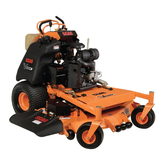
OPERATOR'S
MANUAL
V-Ride
Model:
SVR36A-600FX
SVR48V-691FX
SVR52V-730FX
SVR61V-801FX
Part No. 03321
Printed 9/12
Printed in USA
Advertisement
Table of Contents

Related Manuals for Scag Power Equipment V-Ride SVR52V-730FX


Summary of Contents for Scag Power Equipment V-Ride SVR52V-730FX
- Page 1 Before operating your machine, please read all the information enclosed. © 2012 Part No. 03321 Scag Power Equipment Printed 9/12 Division of Metalcraft of Mayville, Inc. Printed in USA...
- Page 2 SvR36A-600FX with a serial number of H3700001 to H3799999 SvR48v-691FX with a serial number of H3800001 to H3899999 SvR52v-730FX with a serial number of H3900001 to H3999999 SvR61v-801FX with a serial number of H4000041 to H4099999 Always use the entire serial number listed on the serial number tag when referring to this product.
-
Page 3: Table Of Contents
Table of Contents Table of Contents SECTION 1 - GENERAL INFORMATION ...................1 1.1 INTRODUCTION ............................1 1.2 DIRECTION REFERENCE ...........................1 1.3 SERvICING THE ENGINE AND DRIvE TRAIN COMPONENTS ..............1 1.4 SYMBOLS ..............................2 SECTION 2 - SAFETY INFORMATION ..................3 2.1 INTRODUCTION ............................3 2.2 SIGNAL WORDS ............................3 2.3 BEFORE OPERATION CONSIDERATIONS ....................3 2.4 OPERATION CONSIDERATIONS ........................4... - Page 4 Table of Contents SECTION 6 - ADJUSTMENTS ....................21 6.1 PARkING BRAkE ADJUSTMENT ......................21 6.2 TRAvEL ADJUSTMENT ..........................21 6.3 THROTTLE CONTROL AND CHOkE ADJUSTMENTS ................23 6.4 BELT ADJUSTMENTS ..........................23 6.5 BELT ALIGNMENT .............................23 6.6 CUTTER DECk ADJUSTMENTS ......................23 6.7 ELECTRIC CLUTCH ADJUSTMENT ......................28 6.8 FRONT WEIGHT ADJUSTMENT ......................28 6.9 OPERATOR CUSHION ADJUSTMENT .....................29 SECTION 7 -...
-
Page 5: General Information
Scag service parts. All information is based upon product information available - IMPORTANT - at the time of approval for printing. Scag Power Equipment The replacement of any part on this product reserves the right to make changes at any time without by other than the manufacturer's authorized notice and without incurring any obligation. -
Page 6: Symbols
Section 1 SYMBOLS SYMBOL DESCRIPTION SYMBOL DESCRIPTION Choke Transmission Parking Brake Spinning Blade 48071S On/Start Spring Tension on Idler Off/Stop Falling Hazard Thrown Object Hazard Fast Slow Continuously Variable - Linear Cutting Element - Basic Symbol Pinch Point Cutting Element - Engage 481039S Hour meter/Elapsed Operating Hours Cutting Element - Disengage... -
Page 7: Safety Information
Section 2 SAFETY INFORMATION INTRODUCTION DANGER Your mower is only as safe as the operator. Carelessness or operator error may result in serious bodily injury The signal word “DANGER” denotes that an extremely or death. Hazard control and accident prevention are hazardous situation exists on or near the machine that dependent upon the awareness, concern, prudence, and could result in high probability of death or irreparable injury... -
Page 8: Operation Considerations
Section 2 DO NOT allow children to ride or play on the Be sure the interlock switches are functioning machine, it is not a toy. correctly. Clear the area to be mowed of objects that could be Fuel is flammable; handle it with care. Fill the fuel picked up and thrown by the cutter blades. - Page 9 Section 2 Immediately apply the parking brake if you lose steering control while operating. Inspect the machine and correct the problem before continuing to operate. When using any attachment, never direct the discharge of material toward bystanders or allow anyone near the machine while in operation. Start the engine with the operator in the operating position, cutter blades are disengaged, parking brake is engaged, and the neutral lever is in neutral.
-
Page 10: Maintenance Considerations & Storage
Section 2 Tie the mower down securely using the tie down Do not change the engine governor settings or points located on the front and rear of the machine. overspeed the engine. See the engine operator's See Figure 2-2 and 2-3. Secure using straps, chains, manual for information on engine settings. -
Page 11: Using A Spark Arrestor
Section 2 USING A SPARk ARRESTOR The engine in this machine is not equipped with a spark arrestor muffler. It is in violation of California Public Resource Code Section 4442 to use or operate this engine on or near any forest covered, brush covered or grass covered land unless the exhaust system is equipped with a spark arrestor meeting any applicable local or state laws. -
Page 12: Safety And Instructional Decals
Section 2 SAFETY AND INSTRUCTIONAL DECALS 483402 483407 Avoid injury from burns - Shut off engine - Allow to cool several minutes - Remove cap slowly - Do not over fill 484281 483406 Avoid injury from burns - Shut off engine - Allow to cool several minutes - Remove cap slowly - Do not over fill... -
Page 13: Specifications
ENGINE General Type ....................Heavy Duty Industrial/Commercial Gasoline Model: Scag Model SVR36A-600FX ......................Kawasaki FX600V Scag Model SVR48V-691FX ......................Kawasaki FX691V Scag Model SVR52V-730FX ......................Kawasaki FX730V Scag Model SVR61V-801FX ......................Kawasaki FX801V Displacement: Kawasaki FX600V .............................. 603cc Kawasaki FX690V .............................. 726cc Kawasaki FX730V .............................. 726cc Kawasaki FX801V .............................. -
Page 14: Cutter Deck
Section 3 CUTTER DECk Type ........................Out-Front design with anti-scalp rollers Construction ..........................Tri-plate deck construction Top of deck consists of three steel plates totaling nearly 1/2" of steel, 7-gauge (3/16") deck skirt True Cutting Width: 36 .................................35.5" (90.2 cm) 48 ................................48" (122.0 cm) 52 ................................52"... -
Page 15: Operating Instructions
Section 4 OPERATING INSTRUCTIONS Mower Deck Switch (Figure 4-1). Used to engage CAUTION and disengage the mower drive system. Pulling up on the switch will engage the deck drive. Pushing down on the switch will disengage the deck drive. Do not attempt to operate this mower unless you Engine Choke Control (Figure 4-1). -
Page 16: Safety Interlock System
Section 4 Left Steering Control / Operator Presence WARNING Control (Figure 4-1). Used to control the mower's left wheel when traveling forward or reverse. See Section 4.5 for further details regarding the mower's Never operate the mower with the interlock travel controls. -
Page 17: Ground Travel And Steering
Section 4 - NOTE - Turn the ignition key to the start position and start the engine. Smooth operation of the steering control levers will produce smooth mower operation. While learning Allow engine to warm before operating the mower. the operation of the steering controls, keep the travel speed low. -
Page 18: Engaging The Deck Drive (Cutter Blades)
Section 4 ENGAGING THE DECk DRIvE (CUTTER PUSH FOR PULL BACK NEUTRAL BLADES) FORWARD FOR REVERSE “N” FOR NEUTRAL LOCK “D” FOR DRIVE Set the throttle at about 3/4 speed. Do not attempt to engage the deck drive at high speed as this shortens the electric clutch life —... -
Page 19: Operating Platform
Section 4 Operating the machine with the platform lowered is To disengage the deck drive, push the switch in to the disengage position. recommended when: Always operate the engine at full throttle to properly • Mowing most areas. maintain cutting speed. If the engine starts to lug •... -
Page 20: Hillside Operation
Section 4 HILLSIDE OPERATION 4.10 AFTER OPERATION Wash the entire mower after each use. Do not WARNING use high pressure spray or direct the spray onto electrical components. DO NOT operate on steep slopes. Under no - IMPORTANT - circumstances should the machine be operated Do not wash a hot or running engine. -
Page 21: Moving Mower With Engine Stopped
Section 4 4.12 MOvING MOWER WITH ENGINE Use the alternate stripe pattern for best lawn appearance. Vary the direction of the stripe each STOPPED time the grass is mowed to avoid wear patterns in the grass. To “free-wheel” or move the mower around without the engine running, place the dump valve levers in the FREE- 4.14 ADJUSTING CUTTING HEIGHT... -
Page 22: Troubleshooting Cutting Conditions
Section 5 TROUBLESHOOTING CUTTING CONDITIONS CONDITION CAUSE CURE STRINGERS - OCCASIONAL Low engine RPM Run engine at full RPM BLADES OF UNCUT GRASS Ground speed too fast Slow speed to adjust for conditions Wet grass Cut grass after it has dried out Dull blades, incorrect sharpening Sharpen blades Deck plugged, grass accumulation... - Page 23 Section 5 TROUBLESHOOTING CUTTING CONDITIONS (CONT'D) CONDITION CAUSE CURE U N E v E N C U T O N F L AT Lift worn from blade Replace blade GROUND - WAvY HIGH-LOW APPEARANCE, SCALLOPED Blade upside down Mount with cutting edge toward ground CUT, OR ROUGH CONTOUR Deck plugged, grass accumulation Clean underside of deck...
- Page 24 Section 5 TROUBLESHOOTING CUTTING CONDITIONS (CONT'D) CONDITION CAUSE CURE SCALPING - BLADES HITTING Low tire pressures Check and adjust pressures DIRT OR CUTTING vERY CLOSE TO THE GROUND Ground speed too fast Slow speed to adjust for conditions May need to reduce ground speed, raise Cutting too low cutting height, change direction of cut, and/or change pitch and level...
-
Page 25: Adjustments
Section 6 ADJUSTMENTS PARkING BRAkE ADJUSTMENT ADJUST LINKAGE FOR 1/4” GAP WARNING DO NOT operate the mower if the parking brake is not operable. Possible severe injury could result. The parking brake linkage should be adjusted whenever the parking brake lever is placed in the “ENGAGE” position and the parking brake will allow the mower to move. - Page 26 Section 6 NEUTRAL ADJUSTMENT LOOSEN JAM NUT -NOTE- Neutral has been set by your Scag dealer at the time of set up and normally does not need to be adjusted. If, however, you find that the neutral has come out of adjustment, follow the procedure below.
-
Page 27: Throttle Control And Choke Adjustments
Section 6 -NOTE- THROTTLE CONTROL AND CHOkE ADJUSTMENTS Before proceeding with this adjustment, be sure that the caster wheels turn freely and that the tire pressure in the drive wheels is correct. If the tire These adjustments must be performed by your Scag dealer pressure is not correct, the machine will pull to the to ensure proper and efficient running of the engine. - Page 28 Section 6 Turn the adjustment bolts on the front and rear CUTTER DECk LEvEL cutter deck adjustment levers clockwise to raise or counter-clockwise to lower the RH side until the The cutter deck should be level from side-to-side for proper distance from the top of the cutter deck to the floor is cutting performance.
- Page 29 Section 6 CUTTER DECK ADJUSTMENT BOLT DECK HEIGHT CONTROL ROD LOOSEN HERE Figure 6-6. Cutter Deck Height Adjustment Rotate the cutter blade on the left side of the cutter deck. Position the cutter blade so it is facing "front to CUTTER DECK ADJUSTMENT back"...
- Page 30 Section 6 Rotate the cutter blade on the right side of the cutter To adjust the Custom-Cut Baffle height: deck. Position the cutter blade so it is facing "front to Park the machine on a flat surface, apply the parking back"...
- Page 31 Section 6 Custom-Cut Baffle Adjustment Mounting Slot Selected Mounting Hardware Location Slot “A” Hole 1 Hole 2 Hole 3 Hole 4 Height (inches) 3-3/4” 4-1/4” 4-3/4” 5-1/4” Slot “B” Hole 2 Hole 3 Hole 4 Height (inches) 3-1/2” 4” 4-1/2” Figure 6-7.
-
Page 32: Electric Clutch Adjustment
Section 6 ELECTRIC CLUTCH ADJUSTMENT ADJUSTMENT NUTS The electric clutch serves two functions in the operation of the mower. In addition to starting and stopping the power flow to the cutter blades, the clutch also acts as a brake to assist in stopping blade rotation when the PTO is switched off or the operator presence circuit is interrupted. -
Page 33: Operator Cushion Adjustment
Section 6 Additional weight can be added to the front of the machine if needed. See Figure 6-11. Remove the front belt cover from the machine. Remove the mounting hardware securing the weight(s) to the front of the machine. Add the desired weight to the machine and secure using the recommended hardware. - Page 34 Section 6 OPERATOR CUSHION ADJUSTMENTS THREE OPERATOR CUSHION LOCATIONS ONE MOUNTING BRACKET LOCATION Figure 6-12. Operator Cushion Adjustment...
-
Page 35: Maintenance
Section 7 MAINTENANCE MAINTENANCE CHART - RECOMMENDED SERvICE INTERvALS HOURS PROCEDURE COMMENTS BREAk-IN 100 200 500 (FIRST 10) Check all hardware for tightness Check hydraulic oil level See paragraph 7.3 Check belts for proper alignment See paragraph 6.5 Check hydraulic hoses for leaks Use extreme caution when checking the hydraulic hoses. -
Page 36: Lubrication
Section 7 MAINTENANCE CHART - RECOMMENDED SERvICE INTERvALS (CONT'D) HOURS PROCEDURE COMMENTS BREAk-IN (FIRST 10) Check hardware for tightness Apply grease to fittings See paragraph 7.2 Check hydraulic oil level See paragraph 7.3 Change engine oil See paragraph 7.4 Change engine oil filter See paragraph 7.4 Replace engine fuel filter See paragraph 7.5... - Page 37 Section 7 GREASE FITTING LUBRICATION Lubricant Interval Lithium MP White Grease 2125 (40 Hours/Weekly) Chassis Grease (100 Hours/Bi-weekly) Chassis Grease (200 Hours/Monthly) Figure 7-1. Lubrication Fitting Points...
-
Page 38: Hydraulic System
Section 7 HYDRAULIC SYSTEM B. CHANGING HYDRAULIC OIL The hydraulic oil should be changed after every 500 hours A. CHECkING HYDRAULIC OIL LEvEL or annually, whichever occurs first. The oil should also be changed if the color of the fluid has become black or milky. The hydraulic oil level should be checked after the first 8 A black color and/or a rancid odor usually indicates possible hours of operation. -
Page 39: Engine Oil
Section 7 B. CHANGING ENGINE CRANkCASE OIL After the first 20 hours of operation, change the engine crankcase oil and replace the oil filter. Thereafter, change the engine crankcase oil after every 100 hours of operation or monthly, whichever occurs first. Refer to the Engine Operator’s Manual furnished with this mower for instructions. -
Page 40: Engine Fuel System
Section 7 ENGINE FUEL SYSTEM To avoid personal injury or property damage, use extreme care in handling gasoline. Gasoline is extremely flammable and the vapors are explosive. DANGER Extinguish all cigarettes, cigars, pipes and other sources of ignition. Use only an approved gasoline container. To avoid injury from burns, allow the mower to cool before removing the fuel tank cap and Never remove the gas cap or add fuel with the... -
Page 41: Engine Air Cleaner
Section 7 BATTERY - ELECTRIC START MODELS WARNING Lead-acid batteries produce flammable and explosive gases. To avoid personal injury when checking, testing or charging batteries, DO NOT use smoking materials near batteries. keep arcs, sparks and flames away from batteries. Provide proper ventilation and wear safety glasses. -
Page 42: Drive Belts
Section 7 - NOTE - A. CHARGING THE BATTERY If you experience frequent belt wear or breakage, see your authorized Scag service center for belt Refer to the battery charger’s manual for specific adjustment. instructions. Under normal conditions the engine’s alternator will have WARNING no problem keeping a charge on the battery. - Page 43 Section 7 - NOTE - Raise the mower deck to the highest position. Place the lanyard pin in the highest cutting height position Keep the blades sharp. Cutting with dull blades not to prevent the cutter deck from falling. only yields a poor mowing job, but slows the cutting speed of the mower and causes extra wear on the Secure the cutter blades to prevent them from engine and the blade drive by pulling hard.
-
Page 44: Tires
Section 7 HEX NUT-TORQUE TO 75 LB-FT SPINDLE SHAFT CUTTER DECK HEX HEAD BOLT / NUT SPINDLE ASSEMBLY CUTTER BLADE SPACER CUTTER BLADE WASHER HEX HEAD BOLT Figure 7-8. Blade Replacement 7.10 TIRES Check the tire pressures after every 8 hours of operation or daily. - Page 45 Section 7 NOTES...
-
Page 46: Illustrated Parts List
Section 8 ILLUSTRATED PARTS LIST SCAG APPROvED ATTACHMENTS AND ACCESSORIES. Attachments and accessories manufactured by companies other than Scag Power Equipment are not approved for use on this machine. Scag approved attachments and accessories: • Mulch Plate (p/n 9258, 9286, 9287, 9288) •... - Page 47 Section 8...
-
Page 48: 36A Cutter Deck
Section 8 36A CUTTER DECk... - Page 49 Section 8 36A CUTTER DECk Ref. Ref. Part No. Description Part No. Description 481025 Seal, Lower 462361 Cutter Deck w/Decals - 36A 43297 Bushing, Lower 04020-09 Nut, 5/8-11 UNC 481035 Nut, Special 1-1/16" - 18 04001-172 Bolt, Hex Head 1/4-20 x 1" 483174 Pad, Deck Wear 48926...
-
Page 50: 48V & 52V Cutter Decks
Section 8 48v & 52v CUTTER DECkS 52” Only... - Page 51 Section 8 48v & 52v CUTTER DECkS Ref. Ref. Part No. Description Part No. Description 462237 Cutter Deck w/Decals (48V) 481025 Seal, Lower 43297 Bushing, Lower 462362 Cutter Deck w/Decals (52V) 481035 Nut, Special 1-1/16" - 18 04020-09 Nut, 5/8-11 UNC 483176 Pad, Deck Wear 04001-172...
-
Page 52: 61V Cutter Deck
Section 8 61v CUTTER DECk... - Page 53 Section 8 61v CUTTER DECk Ref. Ref. Part No. Description Part No. Description 481025 Seal, Lower 04020-09 Nut, 5/8-11 UNC 43297 Bushing, Lower 04001-172 Bolt, Hex Head 1/4-20 x 1" 481035 Nut, Special 1-1/16" - 18 48926 Tapered Hub 483176 Pad, Deck Wear 483286 Pulley, 6.32 O.D.
-
Page 54: Svr36A, Svr48V & Svr52V Cutter Deck Controls
Section 8 SvR36A, SvR48v & SvR52v CUTTER DECk CONTROLS 5 11 33 34 2011 SVR CDC... - Page 55 Section 8 SvR36A, SvR48v & SvR52v CUTTER DECk CONTROLS Ref. Ref. Part No. Description Part No. Description 04021-20 Nut, Elastic Stop 1"-14 481625-01 Knob w/Stud 481657 Bearing w/Race 491536 Belt Cover w/Decals (36A) 481025 Seal, 2" OD x 1.625 ID 491537 Belt Cover w/Decals (48V &...
-
Page 56: Svr61V Cutter Deck Controls
Section 8 SvR61v CUTTER DECk CONTROLS 18 16... - Page 57 Section 8 SvR61v CUTTER DECk CONTROLS Ref. Ref. Part No. Description Part No. Description 04021-20 Nut, Elastic Stop 1"-14 481625-01 Knob w/Stud 481657 Bearing w/Race 491616 Belt Cover w/Decals (61V) 481025 Seal, 2" OD x 1.625 ID 452063 Arm Weldment, RH 451658 Caster Yoke Weldment 04021-07...
-
Page 58: Svr Sheet Metal Components
Section 8 SvR SHEET METAL COMPONENTS SVR61 Only SVR61 Only... - Page 59 Section 8 SvR SHEET METAL COMPONENTS Ref. Ref. Part No. Description Part No. Description 425501 Brake Shaft Support (61 only) 462240 Instrument Panel w/Decal 452164 Fender Weldment (61 only) 04001-06 Bolt, Hex Head 1/4-20 x .63 481714 Mudflap (61 only) 481625-01 Knob w/Stud 425084...
-
Page 60: Steering Controls
Section 8 STEERING CONTROLS 47 48 SVR-36A 2012 SVR Steering Controls SVR-36A SVR-48V SVR-52V... - Page 61 Section 8 STEERING CONTROLS Ref. Ref. Part No. Description Part No. Description 452055 Brake Paddle Weldment, LH 484093 Knob, Soft Touch 452167 Brake Paddle Weldment - SVR-61V 04020-12 Nut, Jam 3/8-16 04001-32 Bolt, Hex Head 3/8-16 x 1-1/4" 452118 Handle Weldment 04040-12 Flatwasher, 3/8-.438 x 1.0 x .083 483601...
-
Page 62: Svr Fuel System
Section 8 SvR FUEL SYSTEM TO FUEL FILTER To Engine Purge Port Tank Purge... - Page 63 Section 8 SvR FUEL SYSTEM Ref. Part No. Description 483617 Fuel Hose, 1/4" ID (order by inch) 48059-01 Clamp, Fuel Hose 462376 Fuel Tank Assembly - SVR-36A / SVR-48V 462377 Fuel Tank Assembly - SVR-52V / SVR-61V 483896 Valve, Fuel Shut Off 482571 Bushing, .56 Dia.
-
Page 64: Hydraulics And Engine Components
Section 8 HYDRAULICS AND ENGINE COMPONENTS... - Page 65 Section 8 HYDRAULICS AND ENGINE COMPONENTS Ref. Ref. Part No. Description Part No. Description 04063-28 Key, 1/4 x 1/4 x 3-1/2" 484101 Engine, Kawasaki FX600V 483802 Pulley, 4.75 OD - 1.125" Bore 484102 Engine, Kawasaki FX691V 04001-32 Bolt, Hex Head 3/8-16 x 1-1/4" 483968 Engine, Kawasaki FX730V 04030-04...
-
Page 66: Svr-61V Hydraulics And Engine Components
Section 8 SvR-61v HYDRAULICS AND ENGINE COMPONENTS... - Page 67 Section 8 SvR-61v HYDRAULICS AND ENGINE COMPONENTS Ref. Ref. Part No. Description Part No. Description 04063-28 Key, 1/4 x 1/4 x 3-1/2" 484219 Engine, 29hp Kawasaki FX 483802 Pulley, 4.75 OD - 1.125" Bore 484317 Cooler, Transmission (61V) 04001-32 Bolt, Hex Head 3/8-16 x 1-1/4" 48136-13 Clamp, .69 Max Dia.
-
Page 68: Electrical System
Section 8 ELECTRICAL SYSTEM... - Page 69 Section 8 ELECTRICAL SYSTEM Ref. Part No. Description 462240 Instrument Panel w/Decal 483957 Switch, PTO - 10 Amp 48798 Key Switch 48017-03 Lockwasher, 5/8" Internal Tooth 48017-04 Nut, 5/8-32 Special 462069 Key Chain w/ Keys 483609 Key w/Shroud 483976 Choke Control, SVR 483975 Throttle Control, SVR 04003-43...
-
Page 70: Replacement Decals And Information Plates
Section 8 REPLACEMENT DECALS AND INFORMATION PLATES Hea vy- Duty Comm e rcial 484453... - Page 71 Section 8 REPLACEMENT DECALS AND INFORMATION PLATES Ref. Part No. Description 483402 Decal, Warning - Belt Cover 483405 Decal, Warning 483961 Decal, Belt Cover 483059 Decal, 36A 483199 Decal, 48V 483200 Decal, 52V 483201 Decal, 61V 483407 Decal, Spinning Blades 48404 Decal, Metalcraft - Made in USA 483977...
-
Page 72: Svr Electrical Schematic
Section 8 SvR ELECTRICAL SCHEMATIC SWITCH YEL W/RED STRIPE HOURMETER BLACK YEL W/RED STRIPE WHITE SWITCH GREEN BLUE NEUTRAL INTERLOCK SWITCH GREEN BLACK W/RED STRIPE 20 AMP FUSE YELLOW YELLOW 20 AMP FUSE RED W/WHITE STRIPE GREEN BLACK BLACK OPERATOR BLACK PRESENCE BLACK W/RED STRIPE... -
Page 73: Limited Warranty - Commercial Equipment
Cutter decks are warranted against cracking for a period of three (3) years. (parts and labor 1st and 2nd year; parts only 3rd year.) The repair or replacement of the cutter deck will be at the option of Scag Power Equipment. We reserve the right to request compo- nents for evaluation. - Page 74 © 2012 Scag Power Equipment Division of Metalcraft of Mayville, Inc.